Article

Design of Optimized Energy Management Strategy for All-Wheel-Drive Electric Vehicles

Laboratory of Low Emission Vehicle, Beijing Institute of Technology, Beijing 100081, China
*
Author to whom correspondence should be addressed.
Appl. Sci. 2021, 11(17), 8218; https://doi.org/10.3390/app11178218
Submission received: 5 August 2021 / Revised: 30 August 2021 / Accepted: 31 August 2021 / Published: 4 September 2021
(This article belongs to the Section Robotics and Automation)

Abstract

:
The performance of the all-wheel-drive electric vehicle is inseparable from the energy management strategy (EMS). An outstanding EMS could extend the cycling mileage, coordinating the power output of the battery and exerts the advantage of the motor comprehensively. However, the current EMS has poor performance in real-time, and this paper proposes the dynamic programming coordination strategy (DPCS) to solve the problem. Firstly, the EMS based on a rule-based control strategy (RBCS) is applied in a different driving cycle. Secondly, the dynamic programming algorithm (DP) is proposed in the process. The DPCS cooperated the advantage of RBCS and DP, extracting the boundary parameters along with the demand power and vehicle speed. Finally, the number of motors joined in the driving condition is elucidated and the method obtains the optimal torque split ratio through a partly-known driving cycle. By incorporating the thought of a basis of rules, the DPCS determines the torque of each motor that confirm the motor working in an efficient range that incorporates the mind of dynamic programming. The method is validated through the simulation. The results show that the strategy can significantly improve the mileage of the driving cycle, with comprehensive performance in energy distribution and utilization.

1. Introduction

With the development of battery technology, pure electric vehicles occupy an increasingly large proportion of the way people travel nowadays. The electric configuration can briefly be divided into driving by front motor, rear motor, and driving by four in-wheel motor. The difference in each vehicle configuration is that the power and the control strategy used in each model are different. Electric vehicles (EVs), with the benefit of low cost and zero-emission [1,2], are widely used. In addition, the EV has the advantage of high torque reserve at low speed in the driving system, which can realize the shift frequently switch in the start–stop mode and with the recovery of braking energy [3,4,5].
The all-wheel-drive electric control strategy (EMS) is central, and an excellent EMS is the foundation of the EV’s comprehensive performance. The EMS ensures the optimal torque distribution in front and rear shifts, including driving and braking mode. Many methods have been studied in the EV control process. The dominant thoughts of energy management can be classified into rule-based EMS and optimization-based EMS [6,7]. The rule-based control strategy is widely used in the vehicle control unit (VCU) for its simplified calculation in VCU. However, the rule-based EMS of the determined threshold has poor adaptability to dynamic conditions. In recent years, more attention has been paid to EVs’ energy management control strategy. For example, some researchers proposed a genetic algorithm to optimize the torque distribution ratio considering constraints of motor characteristics [8]. Other researchers used the least-squares method to get the control logic of the in-wheel motor [9]. Xie [10] coupled the following distance and power distribution of the electric truck in a model predictive controller and co-optimized the safety and energy consumption. Lin [11] proposed an intelligent energy control strategy that combines fuzzy controller and Savitzky–Golay selective filtering for hybrid storage system control. Huang [12] presents a model predictive control (MPC) power management strategy for a novel anti-idling system, designed for service vehicles. The MPC requires the driving cycle or driver command as a priori information to be known. Chen [13] introduces an online and intelligent energy management controller to improve the fuel economy of a power split for PHEV. The genetic algorithm is used to optimize the engine power threshold. Off-line global optimal torque distribution is frequently executed in plug-in hybrid electric vehicles (PHEVs). In terms of all-wheel-drive EVs’ energy management strategy, Ju [14] present an adaptive equivalent consumption minimization strategy (A-ECMS) for a four-wheel-drive hybrid powertrain system. The results show that A-ECMS achieves better fuel economy than regular ECMS. Song [15] proposed a charge depletion/charge sustaining strategy for an all-wheel-drive plug-in hybrid electric vehicle to realize the torque distribution mainly according to the engine optimal working region to achieve better fuel economy. The traction enhancement is beneficial to the improvement of fuel efficiency. Cao [16] proposed a multi-objective optimal torque distribution strategy, taking into account the front and rear axle load transfer and the variations of adhesion characteristics. The advantages of the proposed strategy are verified through simulation studies in terms of vehicle energy consumption and wheel slip ratio. The attainment of the online torque distribution algorithm goal is to reflect vehicle dynamic driving cycle characters and energy efficiency. However, the traditional dynamic programming (DP) algorithm is mostly involved in known conditions, and the traffic information is measured previously. The off-line global optimal torque distribution is restricted in real-time application. In the actual driving cycle, the next-moment speed will correlate with the current status, and the status is not associated with the previous speed. Thus, this character agrees with the Markov-chain model perfectly. The Markov process is a typical stochastic process. To overcome the disadvantages of off-line driving cycle conditions, the Markov-chain model was operated to forecast vehicle velocity in the driving cycle with consideration of traffic information [17]. For technology restrictions, obtaining real-time traffic information is difficult in the driving cycle. The currently used DP algorithms do not consider the condition of real-time traffic information, but the real-time traffic condition has a great influence on control strategy [18]. Hence, the DP and rule-based algorithms proposed above offset each other, and the system of energy consumption is calculated along with the battery state of charge (SOC) in an optimized trajectory. Compared with the charge deputy (CD) and charge sustain (CS) control process, the vehicle velocity predicting model has significant advantages with low consumption, and sustaining SOC value is relatively high at the end of driving. This is the advantage of online global optimal torque distribution.
In this paper, the permanent magnet synchronous motor (PMSM) model measured by experimental and vehicle model was established. Consequently, the vehicle model and PMSM mathematic model were calculated combining with the dynamic programming coordination algorithm to guarantee the PMSM operation in a high-efficiency range. Thus, the mileage of the vehicle cycle can be improved in a further step. What is more, the power flow model of the vehicle is constructed based on the vehicle longitudinal dynamic equation. The transmission of energy flow begins with the permanent magnet synchronous motor; then, the energy flow reaches the in-wheel motor to drive the vehicle finally. The purpose of optimal torque distribution is to optimize the energy distribution of four PMSMs’ electric energy consumption in the driving cycle. The current BR cannot react to the dynamic driving cycles in the future and thus has a bad real-time performance. The paper proposes the dynamic programming coordination strategy, and the DPCS cooperates with the advantage of RBCS and DP, extracting the boundary parameters along with the demand power and vehicle speed. Finally, the number of motors joined in the driving condition is elucidated, and the method obtains the optimal torque split ratio through a partly-known driving cycle. Through incorporating the thought of the basis of rules, the DPCS determines the torque of each motor, confirming that the motor is working in the efficient range. The method can significantly improve the mileage of the driving cycle, with comprehensive performance in energy distribution and utilization.

2. Design of All-Wheel Driving Model

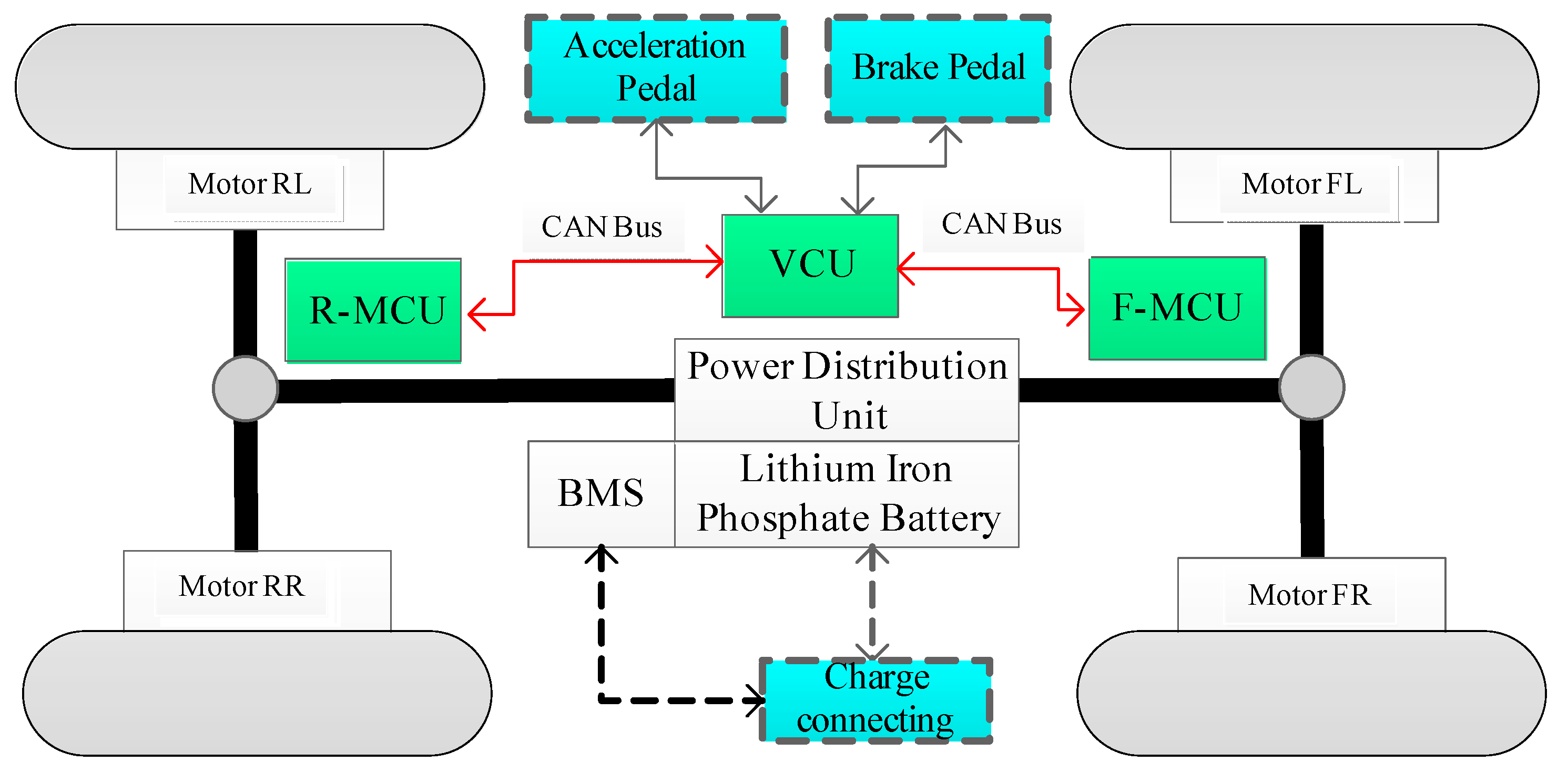
2.1. Power Flow Modeling

On the basis of the balance of vehicle longitudinal dynamics, traction required by the vehicle F(t) is used to overcome rolling resistance, air friction, and pushing vehicle acceleration. Then, the formula expressing the dynamic model is presented as Equation (1). The power comes from the motors and transmits to wheels, respectively. The expression of the transmission process is employed as the following formula, and the parameters of the PHEV are shown in Table 1.
m v = F t ( t ) μ m g cos α 1 2 ρ A C d v 2
F t ( t ) = T dem r
T dem = ( T e 1 + T e 2 + T e 3 + T e 4 ) η i
P in = P dem η i
P dem = T dem w
w ( t ) = v ( t ) r

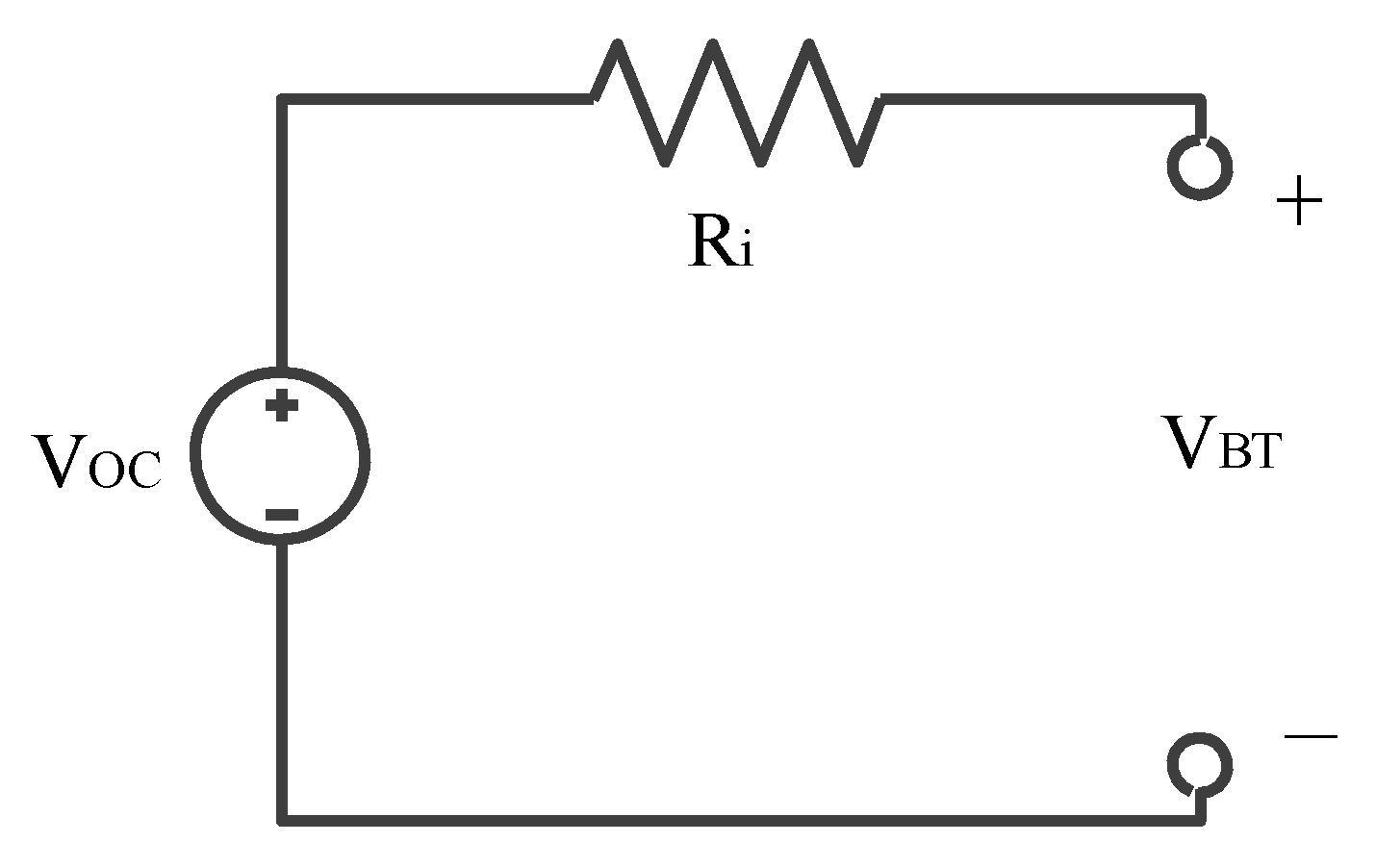
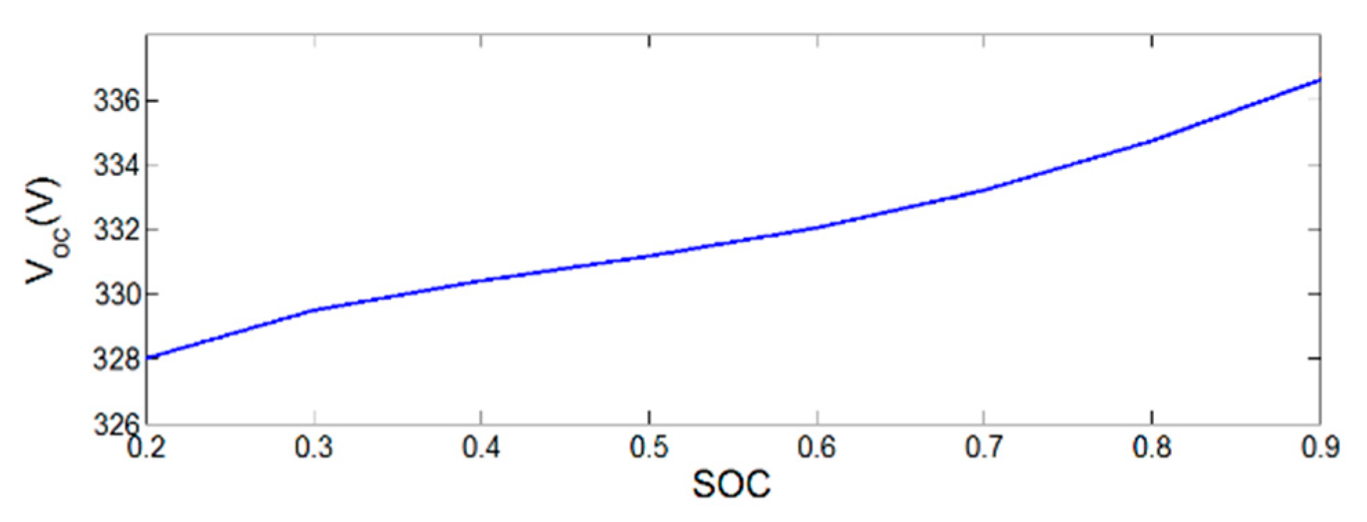
2.2. Power System Modeling

The source of power comes from permanent magnet synchronous motors (PMSM). In PHEV, the driving mode or braking energy recovery mode corresponds to PMSM working as a tractor motor or generator, respectively. The PMSM model is established through experiments, in which PMSM motor data that indicate the torque corresponds to different speeds calculated as motor efficiency are measured by the test platform. When PMSM works as a tractor motor, the PMSM power Pm can be calculated by Equation (7). Meanwhile, when the PMSM works as a generator, Pg could be obtained by Equation (8).
P m = T m w m η m
P g = T m w m η g
where η m and η g are PMSM efficiency while PMSM works as tractor motor or generator, respectively. η m and η g could be obtained through previous experiments. The PMSM efficiency diagram is shown in Figure 1.
Power battery is established through the Rint model [19], and the battery is composed of a generous battery cell. According to Ohm’s law, the diagram of the equivalent circuit diagram is shown in Figure 2. The open-circuit voltage and current are expressed in:
V BT ( S O C , I BT ) = V OC ( S O C ) R i ( S O C , sign ( I BT ) ) I BT
The open voltage is related to state-of-charge (SOC). Furthermore, the voltage of the open circuit VOC is measured with the battery discharge along with different SOC. The battery’s open-circuit voltage corresponding to SOC is shown in Figure 3. The experiment carries on at an ambient temperature, so the influence of temperature on SOC is ignored. According to Equation (9), the battery power of output can be obtained:
P BT = V BT I BT = V OC I BT R i I BT 2
where the R i is initial resistance of the battery. VBT (SOC, IBT) is battery voltage that applies to load, and IBT is output current of the battery which could be calculated by:
I BT = V OC ( S O C ) V OC 2 ( S O C ) 4 R i ( S O C , sign ( I BT ) ) P BT 2 R i ( S O C , sign ( I BT ) )
Thus, the state equation of SOC is presented as follows:
S O C ( k ) = 1 Q 0 k 1 k I BT ( S O C ( k 1 ) , sign ( P BT ) ) d t + S O C ( k 1 )  
where the Q0 is the Maximum capacity of the battery, SOC(k) is the SOC of k at this moment.
The configuration of the four in-wheel motor EV is shown in Figure 4. The front-left and right motor are controlled by the front motor control unit (F-MCU). The configuration of the rear-left and right motor is the same as the front. The EV’s control unit (VCU) is connected with F-MCU and R-MCU by CAN bus.
There are three driving forms in driving mode, front driving mode, rear driving mode, and coupling operation of front and rear drive mode, respectively. Thus,
Pdem = { P f 1 + s f ( t ) P f 2 P r 1 = P r 2 = 0 P r 1 + s r ( t ) P r 2 P f 1 = P f 2 = 0 P r 1 + P r 2 + P f 1 + P f 2
s ( t ) = { 1 ,   motor   on 0 ,   motor   off
When the VCU receives the signal of the brake pedal of the four in-wheel motors working together in breaking mode, the braking power is given by Equation (15). According to the demand level of the brake pedal, the electric braking will work firstly, and once the demand level of the breaking pedal exceeds 30% of all ranges, the mechanical braking and electric braking will work together to maintain braking force. Because electric braking can recover electric energy, and the motor can transfer mechanical energy to electrical energy, then electric breaking can improve the utilization of energy.
P gen = η g ( T gen ( t ) , ω m ( t ) ) T gen ( t ) ω m ( t ) , T gen ( t ) < 0
m r d v d t = T gen ( t ) + T mec ( t )
f f b ( t ) = L r L + a ( t ) g H L
f r b ( t ) = ( 1 f f b ( t ) ) c g
where the f f b ( t ) and f r b ( t ) are the front and rear distribution rate of braking force, respectively. L r is the distance between the rear axle and center of mass, L is the distance between the rear and front wheels. H is the height of the center of the mass from the ground. a(t) is the deceleration in breaking. c g is distribution ratio between breaking torque of front and rear axle.
Where the Pgen is power generation, Tgen (t) is the braking torque produced by the motor, Tmec (t) is mechanical braking torque.
In the condition of normal operation and without considering other electrical devices, the torque distribution coefficient β is defined as the ratio of front axle torque to driving torque, such as Equation (19).
β = T f T f + T r
In real working conditions and modeling, we make the following consumptions for simplicity [8].
  • The two front and rear in-wheel motors have no relative slip in synchronous rotation.
  • The two front and rear in-wheel motors’ configuration is the same, but the output torque depends on applications.
Based on those assumptions and considering longitudinal dynamics in this paper, when the rear or front motor work singularly, the assumptions can be expressed as follows.
  { T f 1 = T f T r 1 = T r
  { T f 1 = β T req T r 1 =   ( 1 β )   T req
In the case of front and rear motor working together, the equation is expressed as:
  { T f 1 = T f 2 = T f 2 T r 1 = T r 2 = T r 2
  { T f 1 + T f 2 = β T req T r 1 + T r 2 =   ( 1 β )   T req
So the efficiency objective function can be acquired by the following equation:
min   J d = w { β T f η f 1 ( T f , w ) + ( 1 β ) T r η r 1 ( T r , w ) + β T f η f 2 ( T f 2 , w ) + ( 1 β ) T r η r 2 ( T r 2 , w ) }
In the whole driving cycle, the control vector is defined as torque split ratio u β (k), and u c (k), indicating which motor is working. Further, in the whole drive, the time interval is selected as 1s, so the discrete-time state equation is given by (25).
X ( k + 1 ) = f ( X ( k ) , U ( k ) ) + X ( k )
where X(k) is the system state vector, U(k) is the system control vector. In the offline optimization process of all-wheel-drive (AWD), energy management is carried out in different driving conditions. For example, the Manhattan bus driving cycle, West Virginia Suburban driving cycle, and typical cities in China driving cycles. With the help of the vehicle longitudinal dynamic theory, the driven torque can be calculated. Therefore, the system state vector can be confirmed as battery SOC and motors’ state.
X ( k ) = [ S O C ( k ) , u s ( k ) ] T
u s ( k ) = { 1 ,   participation 0 ,   withdrawal
For four in-wheel motor independence drives, the input torque consists of rear motors and front motors torque, and the power split ratio which is defined as torque split ratio. Therefore, the control vector could be simplified by
U ( k ) = [ u β ( k ) , u c ( k ) ] T
So, the optimal energy management strategy is described as finding optimal control vector U(k) to minimize cost function Jd and sustain relatively higher SOC in terminal driving. To insurance security and drivability in the driving cycle, the penalty function of torque increases sharply, and motor temperatures are considered in the cost function.
S ( k ) = m | T ( k + 1 ) T ( k ) | n | Q ( k + 1 ) Q ( k ) |
The m is n plenty factors in the optimal process, and Q(k) is the temperature predictor function which is measured in the experiment of different working conditions and recorded. When the temperature of the motor exceeds the threshold, the front driving mode will be replaced by the rear driving mode, corresponding to this condition, when the vehicle working in all driving modes the power of the motor will be limited.
Based on Bellman’s optimization thought, all processes of optimization could be decomposed into a serious minimum optimization problem. The sub-problems are each step of optimal decision, where all processes of optimization control vector U ( k ) consist of the stage of optimal control vector u(k).
U ( k ) = [ u β ( k ) , u c ( k ) ] T
In all optimization, procedures are described as Equations (31) and (32)
Step N − 1:
J N 1 ( X ( N 1 ) ) = min L ( X ( N 1 ) , U ( N 1 ) )
Step k(0 < k < N − 1):
J k ( X ( k ) ) = min [ L ( X ( k ) , U ( k ) + J k 1 ( X ( k 1 ) ) ]
where the J k ( X ( k ) ) is the optimal function of indicator, the optimal control strategy is solved by the above formula in the reserve method. In each moment k, there is always a control vector U ( k ) to optimal indicator function. All processes of dynamic programming are shown in Figure 5. The optimal control vector U ( k ) including different driving cycles is determined through objective function and record with the help of state-space updating.
[ U ( k ) ] = arg min J k ( X ( k ) )
To ensure that each component is working safely, the constraint condition of the part operating status should be created as the following constraints:
ω m , min ω m ( t ) ω m , max
T f - min T f T f - max
T r - min T r T r - max
S O C min S O C ( t ) S O C max
In the equation, ω m , min and ω m , max are the motors minimum and maximum speed, respectively. T f min and T f max are front shaft torque in the current speed and SOC(k) corresponds to the minimum and maximum torque which consists of two motors. T r min , T r max are the same configuration with front shaft torque. S O C ( t ) is the current state of charge, S O C min and S O C max are the healthy range of the battery. In the electric vehicle driving mode, the electric energy should make full use by energy management, and in the starting point and terminal point, SOC is described by
S O C max ( 0 ) = 0.9
S O C min ( N ) = 0.3

3. Design of AWD Optimal Energy Management Strategy Process

3.1. Rule-Based Control Strategy

The state of the battery packs is critical in the process of the vehicle life cycle. To measure the charge of the battery, the threshold is defined as s o c low , s o c cs , s o c CD and s o c high , respectively. The operation can be divided into three modes which are front driving mode, front-rear driving mode, and all-wheel driving mode, separately. All of the driving modes supply energy by the battery system, so according to the driving condition, allocating the energy properly is essential in extending the driving range. In a rule-based control strategy, the torque demand ( P d ) of the system is converted by the operating percentage of the accelerator pedal. In the default model, the torque demand is less than twice the rated torque of the motor, and the vehicle operates in fronting mode. With the increase in the demand power, the rear motors participate in the cycle gradually. When the vehicle demands instantaneous power dramatically or the four-wheel is in tough conditions, the vehicle will carry out in the all-wheel driving mode. The constriction of different operation models of rule-based energy management strategy is presented in Table 2.

3.2. All-Wheel-Driving Optimal Torque Distribution Based on DP

In the research of torque distribution problem, the objective function is given by (24) which is affected by motor torque T f , rotating speed w, and motor efficiency η . The solving torque distribution process is a discontinuous and constrained issue. In the previous study, quadratic programming (QP) was used to solve the problem, which has the defect of much computation, where it is easy to fall into a locally optimal solution [20]. Thus, in the online optimal process, the computation and feasibility algorithm in the vehicle control unit should be considered. In the usual driving cycle, cycle conditions can be defined as traffic congestion in which the motor works in common instantaneous high torque, and in suburban conditions where the motor works in rare start–stop points, and in the high-speed condition where the rear and front motor work in the cooperation mode. In the offline dynamic programming process, the boundary conditions that switch in actual operation can be defined. Simultaneously, the boundary condition parameters are recorded in the embedded system.

3.3. Optimizing Process and Results

In the driving cycle of traffic congestion, suburban conditions and high-speed conditions are shown in Figure 6. To display the different power demands at various speeds, the three typical driving conditions are used in parameter extraction with the help of a rule-based control strategy (RBCS). Figure 7 is the results of optimizing the parameter extraction of the rule-based strategy for three driving cycles. In a single motor driving mode, the vehicle demand power increases with speed linearly. In the single motor mode, two-motor coordination mode, and three-motor coordination mode, the demand power is separated from each other in a low-speed range (25 km/h). The vehicle in low-speed acceleration requires less power than high-speed acceleration. Along the longitudinal axis of vehicle speed, the working vehicle slows down or slides the vehicle demand to no power, and in this condition, all-wheel driving motors have no output power. Thus, in practical application, the rapid prototyping controller will be incorporated in the vehicle control unit (VCU) which in rule-based control strategy (RBCS) or dynamic programming coordination strategy (DPCS), the threshold of speed (25 km/h) and accelerator pedal opening indicate that the power demand will be incorporated in the control strategy.

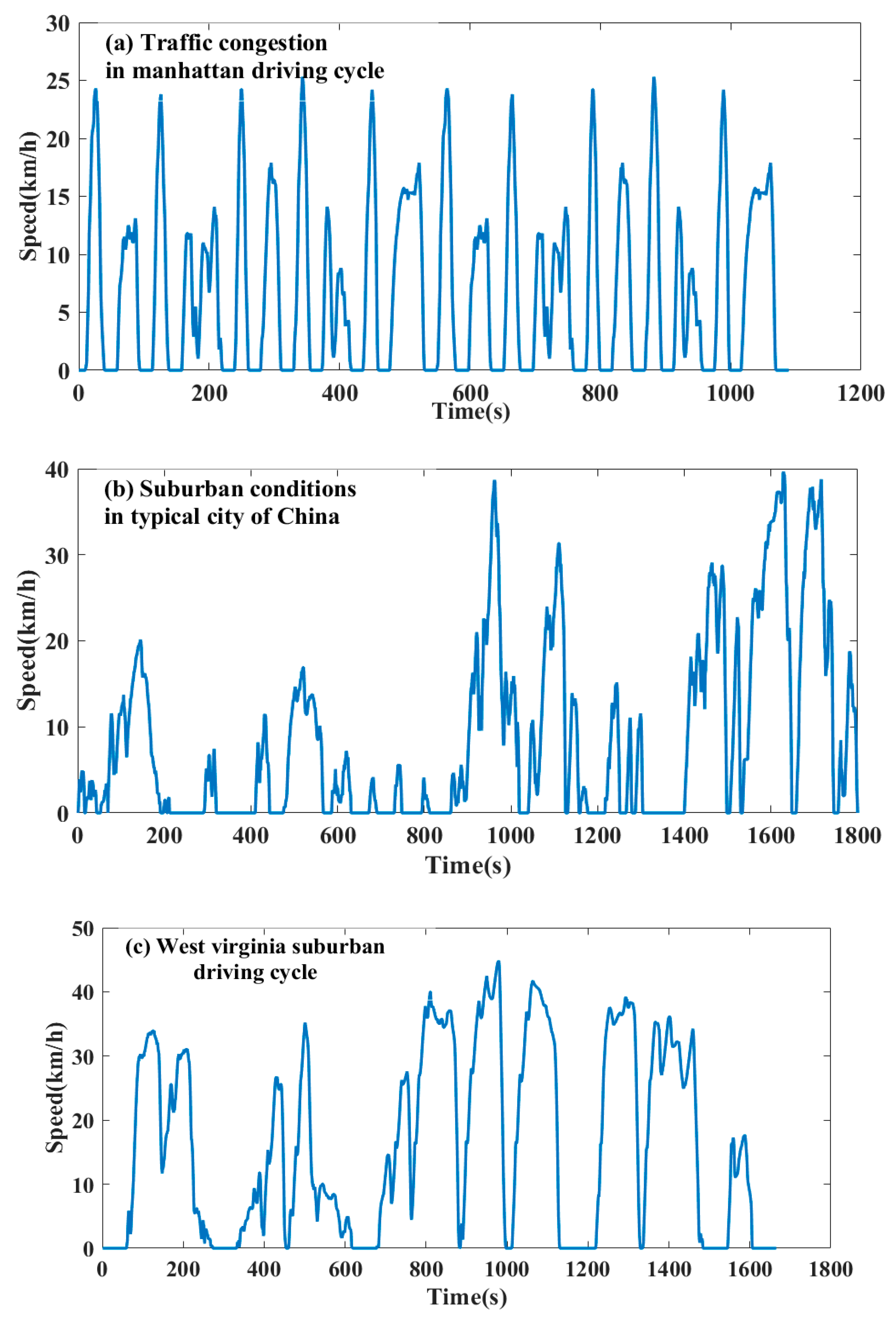
4. Results and Discussion

To overcome the shortcoming of rule-based energy management strategy in adaptation to dynamic driving cycles, the DPCS combines the advantage of rule-based and dynamic programming. The dynamic programming coordination strategy (DPCS) could determine the number of motors joined u c (k) firstly, by incorporating the thought of a rule basis. Then, the DPCS determines the torque of each motor which confirms that the motor is working efficiently, incorporating the mind of dynamic programming. The optimization process of each step is shown in Figure 8. Figure 9 is the SOC curve of a typical city in China’s driving cycle under different control strategies. It donates, in DPCS mode, the joined motor working in an efficient range, with the motor consuming less power to maintain the vehicles; thus, the SOC decreases slower than RBCS mode.
The vehicle demand power can be divided into front power and rear power, such as Equation (19). The torque distribution coefficient β is defined as the ratio of front axle torque to driving torque, in DPCS mode or RBCS mode, and the torque distribution coefficient is presented in Figure 10. In the RBCS mode, the vehicle works in three-motor coordination or all-wheel drive along with the vehicle demand power, while in the DPCS mode, with the increase in vehicle power or decrease in vehicle power, the front motor is always working, indicating that the high torque of the front motor is often provided. Combined with Figure 11, in the DPCS mode, the motor works in an efficient range correspondingly. As shown in Figure 11, the two rear motors work in the same output power, so the rear motor efficiency represents the dynamic programming action effect. In the RBCS mode, the rear motor maintains the efficiency of 0.3 to provide the required power of the vehicle, but in the DPCS mode, the required power of the vehicle is supplied in front motors. Thus, in the DPCS mode, the motor rarely works in inefficient areas.

5. Discussion and Conclusions

This paper proposed energy management for all-wheel-drive electric vehicles based on the partly-known driving cycle. To overcome the shortcoming in real-time of the algorithm, the control strategy was divided into three parts. The parameters that affected the vehicle power demand and speed were extracted, and the torque distribution coefficient was determined according differ driving cycles, which is developed based on dynamic programming coordination strategy (DPCS) and rule-based control strategy (RBCS), respectively. In the end, the extracted parameters as shown in Figure 7 will be used in the on-line control strategy to extend the cycling mileage, and coordinating the power output of the battery and exerts the advantage of the motor comprehensively. The specific work could be summarized as the following aspects.
(1)
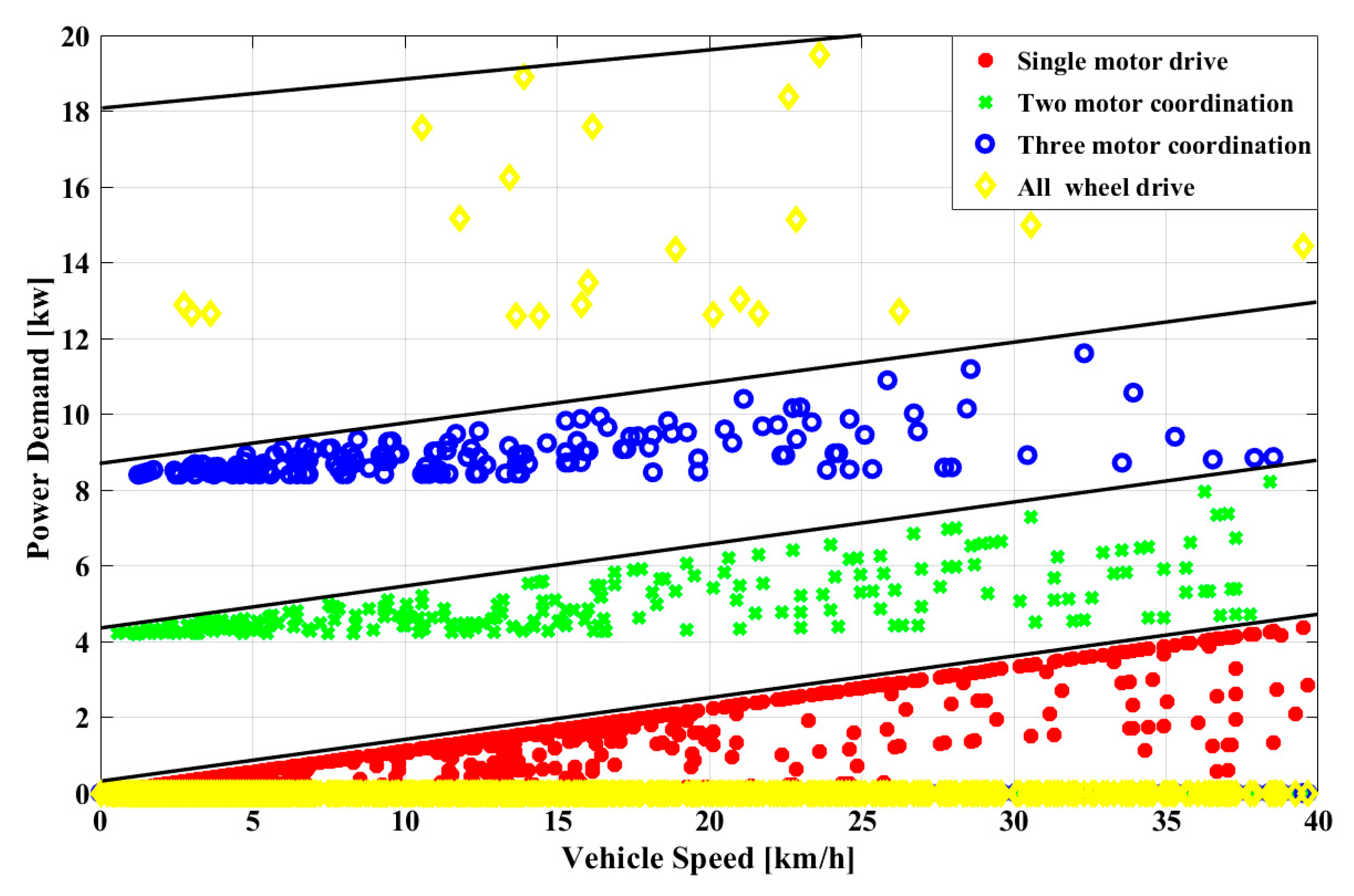
In this paper, based on rule-based and dynamic programming coordination, a control strategy of the offline parameter extraction method is proposed. When the vehicle speed is higher than 25 km/h, the two rear motors get involved, with the front motors working more reasonably, along with increasing the vehicle demand power.
(2)
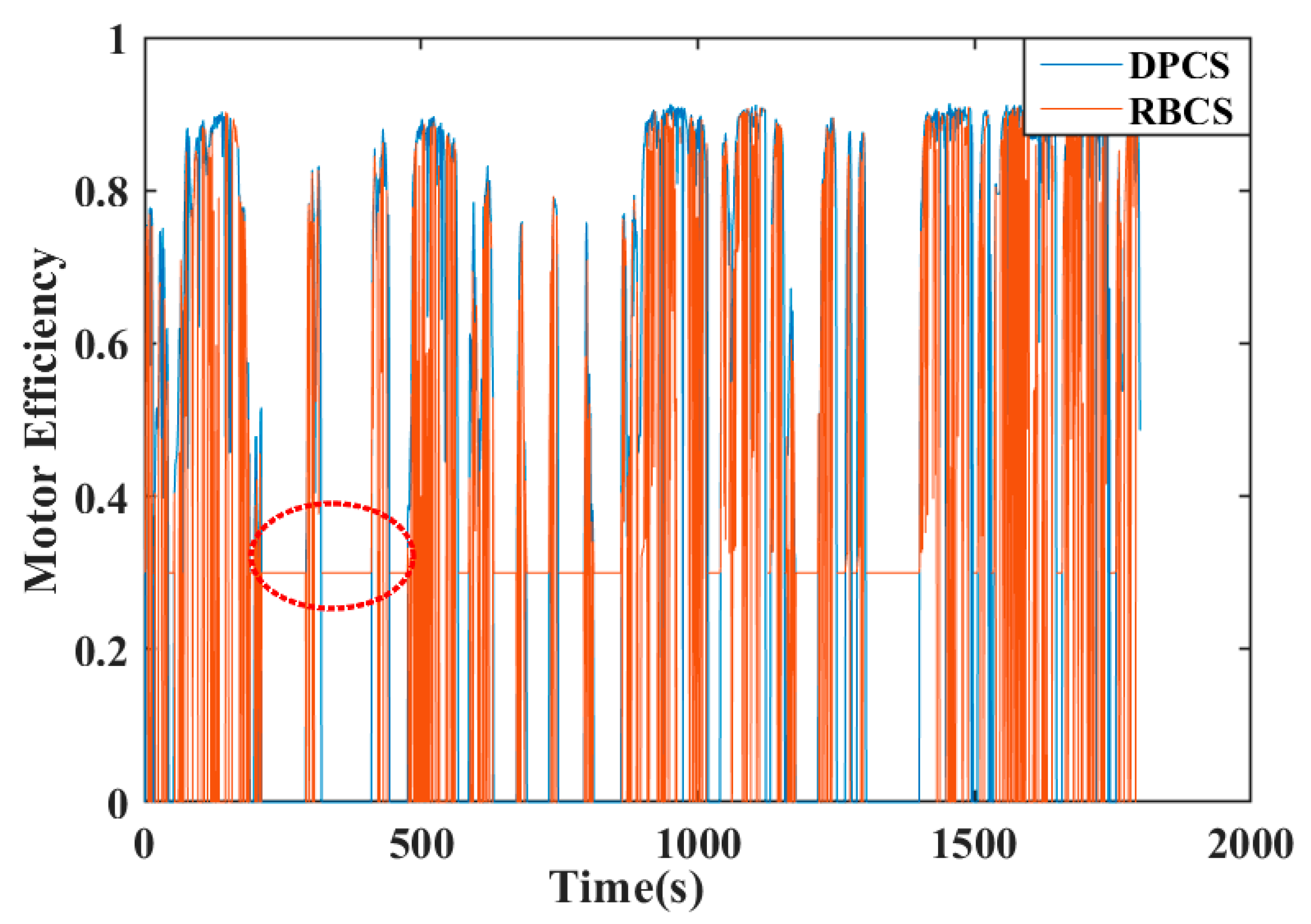
The dynamic programming coordination strategy is proposed, and the method obtains the optimal torque split ratio through a partly-known driving cycle. The benefit of this strategy is using electric power to the greatest extent and taking management of the motor, which will work and put the motor in an efficient range.
(3)
To verify the dynamic programming coordination strategy, the simulation was conducted based on MATLAB/Simulink. According to simulation results, the dynamic programming coordination strategy plays a significant role in all-wheel-drive performance, compared to a rule-based control strategy.

Author Contributions

For this paper, all authors have participated in corresponding researches. H.D. conceived and designed the proposed prototype; L.F., H.D. conceived and performed the experiments; L.F. and H.D. analyzed the data; H.D. wrote the paper. L.F. and Y.Z., revised the English writing of this paper. All authors advised on the manuscript. All authors have read and agreed to the published version of the manuscript.

Funding

This research received no external funding.

Institutional Review Board Statement

Not applicable.

Informed Consent Statement

Not applicable.

Data Availability Statement

Not applicable.

Conflicts of Interest

The authors declare no conflict of interest.

References

  1. Wu, J.; Liang, J.; Ruan, J. A robust energy management strategy for EVs with dual input power-split transmission. Mech. Syst. Signal Process. 2018, 111, 442–455. [Google Scholar] [CrossRef]
  2. Roy, H.K.; Mcgordon, A.; Jennings, P.A. A Generalized Powertrain Design Optimization Methodology to Reduce Fuel Economy Variability in Hybrid Electric Vehicles. IEEE Trans. Veh. Technol. 2014, 63, 1055–1070. [Google Scholar] [CrossRef]
  3. Li, L.; Zhou, L.; Yang, C.; Xiong, R.; You, S.; Han, Z. A novel combinatorial optimization algorithm for energy management strategy of plug-in hybrid electric vehicle. J. Frankl. Inst. 2017, 354, 6588–6609. [Google Scholar] [CrossRef]
  4. Wu, G.; Boriboonsomsin, K.; Barth, M.J. Development and evaluation of an intelligent energy-management strategy for plug-in hybrid electric vehicles. IEEE Trans. Intell. Transp. Syst. 2014, 15, 1091–1100. [Google Scholar] [CrossRef]
  5. Chao, Y.; Liang, L.; You, S.; Yan, B.; Xian, D. Cloud computing-based energy optimization control framework for plug-in hybrid electric bus. Energy 2017, 125, 11–26. [Google Scholar]
  6. Peng, J.; Hao, F.; He, H.; Deng, P. A rule-based energy management strategy for a plug-in hybrid school bus based on a controller area network bus. Energies 2015, 8, 5122–5142. [Google Scholar] [CrossRef] [Green Version]
  7. Fan, L.; Zhang, Y.; Dou, H.; Zou, R. Design of an integrated energy management strategy for a plug-in hybrid electric bus. J. Power Sources 2020, 448, 227391. [Google Scholar] [CrossRef]
  8. Xu, Y.; Jiang, L.; Wei, B.; Qiu, L. An Optimal Torque Distribution Strategy for Four-Motorized-Wheel Electric Vehicle Considering Energy Conversation. IEEE Access 2020, 8, 135975–135988. [Google Scholar] [CrossRef]
  9. Jiang, X.; Chen, L.; Xu, X.; Cai, Y.; Li, Y.; Wang, W. Analysis and optimization of energy efficiency for an electric vehicle with four independent drive in-wheel motors. Adv. Mech. Eng. 2018, 10, 2072045642. [Google Scholar] [CrossRef] [Green Version]
  10. Xie, S.; Lang, K.; Qi, S. Aerodynamic-aware coordinated control of following speed and power distribution for hybrid electric trucks. Energy 2020, 209, 118496. [Google Scholar] [CrossRef]
  11. Lin, K.; Wang, M.; Liu, S. Power distribution strategy based on fuzzy controller and Savitzky-Golay selective filtering in hybrid energy storage system. IOP Conf. Ser. Earth Environ. Sci. 2020, 585, 012031. [Google Scholar] [CrossRef]
  12. Huang, Y.; Khajepour, A.; Wang, H. A predictive power management controller for service vehicle anti-idling systems without a priori information. Appl. Energy 2016, 182, 548–557. [Google Scholar] [CrossRef]
  13. Chen, Z.; Mi, C.C.; Xiong, R.; Xu, J.; You, C. Energy management of a power-split plug-in hybrid electric vehicle based on genetic algorithm and quadratic programming. J. Power Sources 2014, 248, 416–426. [Google Scholar] [CrossRef]
  14. Ju, F.; Zhuang, W.; Wang, L.; Zhang, Z. Optimal sizing and adaptive energy management of a novel four-wheel-drive hybrid powertrain. Energy 2019, 187, 116008. [Google Scholar] [CrossRef]
  15. Song, D.; Li, L.; Zeng, X.; Jiang, Y.; Lei, Y. Traction control–integrated energy management strategy for all-wheel-drive plug-in hybrid electric vehicle. Adv. Mech. Eng. 2017, 9, 168781401774715. [Google Scholar] [CrossRef]
  16. Cao, K.; Hu, M.; Wang, D.; Qiao, S.; Guo, C.; Fu, C.; Zhou, A. All-Wheel-Drive Torque Distribution Strategy for Electric Vehicle Optimal Efficiency Considering Tire Slip. IEEE Access 2021, 9, 25245–25257. [Google Scholar] [CrossRef]
  17. Liu, T.; Hu, X.; Li, S.E.; Cao, D. Reinforcement Learning Optimized Look-Ahead Energy Management of a Parallel Hybrid Electric Vehicle. IEEE/ASME Trans. Mechatron. 2017, 22, 1497–1507. [Google Scholar] [CrossRef]
  18. Yang, Y.; Zhang, Y.; Tian, J.; Zhang, S. Research on a Plug-In Hybrid Electric Bus Energy Management Strategy Considering Drivability. Energies 2018, 11, 2177. [Google Scholar] [CrossRef] [Green Version]
  19. Wang, B.; Xu, J.; Cao, B.; Zhou, X. A novel multimode hybrid energy storage system and its energy management strategy for electric vehicles. J. Power Sources 2015, 281, 432–443. [Google Scholar] [CrossRef]
  20. Yun, S.; Yi, K.; Cheon, S.; Yoon, Y. Development of a Motor Torque Distribution Strategy of Six-Wheel-Driven Electric Vehicles for Optimized Energy Consumption; SAE Technical Papers; SAE: Warrendale, PA, USA, 2019. [Google Scholar]
Figure 1. Efficiency diagram of the motor or generator.
Applsci 11 08218 g001
Figure 2. Model of the battery pack.
Applsci 11 08218 g002
Figure 3. Battery’s open-circuit voltage corresponding to SOC.
Applsci 11 08218 g003
Figure 4. Configuration of PHEV test platform distribution.
Applsci 11 08218 g004
Figure 5. Configuration diagram of dynamic programming algorithm.
Applsci 11 08218 g005
Figure 6. Three driving cycles.
Applsci 11 08218 g006
Figure 7. Rule-based energy allocation of AWD.
Applsci 11 08218 g007
Figure 8. The optimization process of driving torque based on DP.
Applsci 11 08218 g008
Figure 9. SOC curve of a typical city in China under different control strategies.
Applsci 11 08218 g009
Figure 10. Torque distribution coefficient under different control strategies.
Applsci 11 08218 g010
Figure 11. Rear motor efficiency under different control strategies.
Applsci 11 08218 g011
Table 1. Vehicle parameters involved.
SymbolParameterValue/Unit
Te Motor torqueNm
Tdem The final drive output torqueNm
WWheel angular speedRad/s
vVehicle speedm/s
mVehicle mass1890 kg
AVehicle lateral surface3.5 m2
CdAerodynamic coefficient0.73
ρAerodynamic resistance coefficient1.2 kg/m3
Faer Aerodynamic resistanceN
PmRated power of the motorW
Pdem The output power of the final driveW
rTire radius0.354 m
μ Rolling coefficient0.8%
η Efficiency of transmission0.90
Q0Maximum battery chargeC
SOCBattery state of charge
IBTElectric currentA
PBTElectric power of the batteryW
VOCOpen circuit voltageV
RiThe internal resistance of the batteryΩ
VBTThe voltage of the loadV
Table 2. The operation model of rule-based energy management strategy.
Operating ModeConstraint of SOCConstraint of PowerTorque Distribution
Front Driving Mode s o c > s o c low 0 < P d < 2 P m T d = T f 1 ;
T d = T f 1 + T f 2 ;
Front-rear Driving Mode s o c CD < s o c < s o c high 0 < P d < 3 P m T d = T f 1 + T f 2 ;
T d = T f + T r 1 ;
All-Wheel Driving Mode s o c cs < s o c < s o c high 0 < P d < 4 P m T d = T f + T r 1 ;
T d = T f + T r .
Publisher’s Note: MDPI stays neutral with regard to jurisdictional claims in published maps and institutional affiliations.

