Review

Operation and Challenges of Multi-Infeed LCC–HVDC System: Commutation Failure, AC/DC Power Flow, and Voltage Stability

1
Department of Electrical Engineering Technology, National Skills University, Islamabad 44000, Pakistan
2
Department of Electrical Engineering, Balochistan University of Information Technology, Engineering and Management Sciences (BUITEMS), Quetta 87300, Pakistan
3
State Key Laboratory of Alternate Electrical Power System with Renewable Energy Sources, North China Electric Power University, Beijing 102206, China
4
School of Electrical and Electronics Engineering, Chung-Ang University, Dongjak-gu, Seoul 06974, Korea
5
Department of Intelligent Energy and Industry, Chung-Ang University, Dongjak-gu, Seoul 06974, Korea
*
Author to whom correspondence should be addressed.
Appl. Sci. 2021, 11(18), 8637; https://doi.org/10.3390/app11188637
Submission received: 14 August 2021 / Revised: 7 September 2021 / Accepted: 13 September 2021 / Published: 17 September 2021

Abstract

:
This paper presents a detailed analysis of commutation failure, AC/DC power flow, and voltage stability of multi-infeed high-voltage direct current (HVDC). The use of HVDC power transmission technology has become common in modern power systems. During the past two decades, HVDC technology has been extensively used for long-distance bulk power transmission to remote areas. Throughout the world, the demand for power has drastically increased in recent years due to industrialization; such situations make HVDC an economic candidate because the distance between power generation plants and load areas is significantly very long. The line-commutated converter (LCC) technology-based HVDC system is well more mature than other available conversion schemes (i.e., voltage source converters), and it is widely used in high-power projects. China had approximately 50 HVDC–LCC links in 2020, and a single LCC-based link with the highest capacity is 12 GW. The installation of several HVDC links in an existing power network has led to a situation where two or more HVDC links terminate in the electric vicinity of each other’s AC network or even in same AC busbar. Such scenarios are termed multi-infeed HVDC system. Multi-infeed HVDC systems bring various challenges related to voltage stability, local and concurrent commutation failure, and AC/DC power flow. Here, the literature available on these phenomena of LCC-based HVDC is discussed for future research. The assumptions and drawbacks of various techniques used for investigating the mentioned phenomena are also highlighted.

1. Introduction

The first commercial high-voltage direct current (HVDC) power transmission using line-commutated converter (LCC) technology was commissioned in 1954 [1]. The initial projects were built using mercury arc rectifiers. Meanwhile, the advancement in semi-conductor devices has made it possible to build thyristors of high power rating to replace traditional mercury arc rectifiers. The first HVDC with silicon-thyristor-based technology came into use in 1970 [2]. Since then, the use of HVDC in power transmission has become common due to its significant technical and economic benefits over conventional HVAC transmission. In modern power systems, HVDC is being adopted for long-distance bulk power transmission, interconnection of different asynchronous AC systems, underwater power transfer using submarine cables, integration of renewable energy resources, back-to-back power transfer, and control of power flow [3,4]. LCC-based HVDC (classic HVDC) links have been operating with less maintenance, high reliability, and large power capacity in the last half century. The rapid evolution of HVDC links in a power system tends toward situations where two or more HVDC links feed to AC systems that lie in close electric proximity or a common AC system [5]. Such configurations are called multi-infeed HVDC systems. The first multi-infeed HVDC concept was reported in 1972, discussing the harmonic instability and power frequency phenomena of single and multiple infeed DC systems [6]. The interaction between converters in close electric proximity is illustrated in [7] for the first time. It is discussed that multiple DC infeeds potentially degrade the transient performance of the overall HVDC system. Converters in multiple DC infeeds may work as a rectifier/inverter or both (rectifier + inverter). The challenge in the operation of multi-infeed HVDC is the mutual interaction between converters, followed by a temporary disturbance or fault at a common bus or either of the commutating buses. This mutual interaction is one of the major concerns of an AC/DC interconnected system. The interaction between converters largely depends on the AC system strength. The stronger is the AC system, the higher is the ability to regulate voltage during disturbance [8,9]. The AC system strength is location dependent; it means that the AC system strengths for different buses are different. The AC system strength plays a key role in the AC/DC interaction and mutual interaction between converters [10].
Since the advent of HVDC transmission, researchers and the manufacturing industry have been involved in the evaluation of single infeed HVDC systems under normal and abnormal conditions. This is why most of the literature data deal with single infeed HVDC and its parameters. The serious challenge in the evolution of multi-infeed HVDC systems is lack of data and knowledge about the steady state and dynamic behavior of multiple DC infeed systems. The performance of multi-infeed HVDC is largely influenced by the interaction between DC converters and other allied phenomena, which are applicable for single infeed HVDC systems. The effect of an AC system strength on the performance of single infeed HVDC is also true for multi-infeed DC systems. Similarly, reactive power support, commutation failure, transient overvoltage, and fault recovery time are also valid for multi-infeed HVDC systems. Besides these phenomena, interconverter voltage interaction, voltage stability, local and concurrent commutation failure, interconverter direct current interaction, and discrete tap position problem are also new challenges for multi-infeed HVDC systems. These transient phenomena of HVDC are analyzed in PSCAD/EMTDC software. The results are equally acceptable for practical purposes as the software uses interpolation technique to estimate the data. The specific literature available on these topics is discussed in this paper.

2. Multi-Infeed LCC–HVDC System

HVDC converters are classified into two major types: (1) line-commutated converter (LCC–HVDC) and (2) voltage source converter (VSC–HVDC).
In LCC–HVDC, the DC side current is kept constant with minimum ripple. The polarity of DC side voltages determines the direction of the average power flow. A large inductor, connected in series, retains the current continuity similar to a current source. The DC side voltage (Vdc) in an LCC is proportional to the AC side voltage (Vac) multiplied by cos(θ). The θ is the angle between the fundamental frequency component of the phase current and the phase voltage at the AC side. The θ is controlled by adjusting the switching time of thyristors. The AC current is directly proportional to the DC side current because it is created from the switching of the DC current. The polarity of the DC side voltage changes with a firing angle beyond 90°; however, this cannot affect the polarity of the DC current. The turn ON/OFF time of valves is controlled by controlling the firing angle α, which produces firing pulses for valves. One of the most important features of the LCC is the possibility to control the DC side voltage by controlling the firing instant.
In VSC–HVDC, the DC voltage polarity remains the same, and the direction of the average power flow depends on the polarity of the DC current. Typically, the VSC DC terminals and a large capacitor are in parallel, which denotes voltage sources. The VSC entails reverse-conducting electronic switches, which are widely available in the power electronics market, such as IGBT.

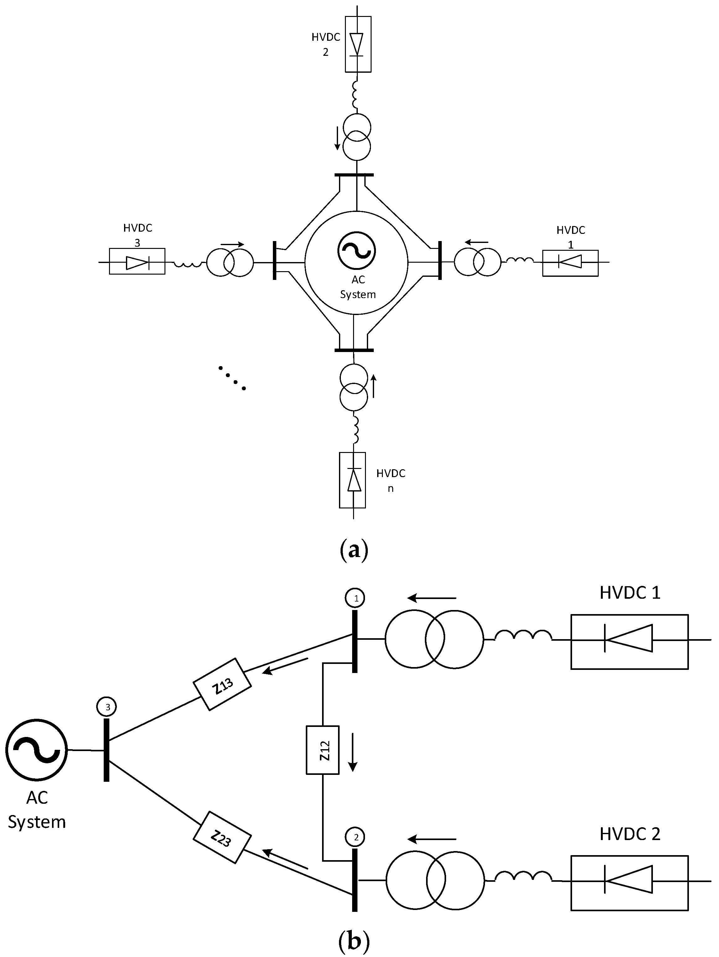
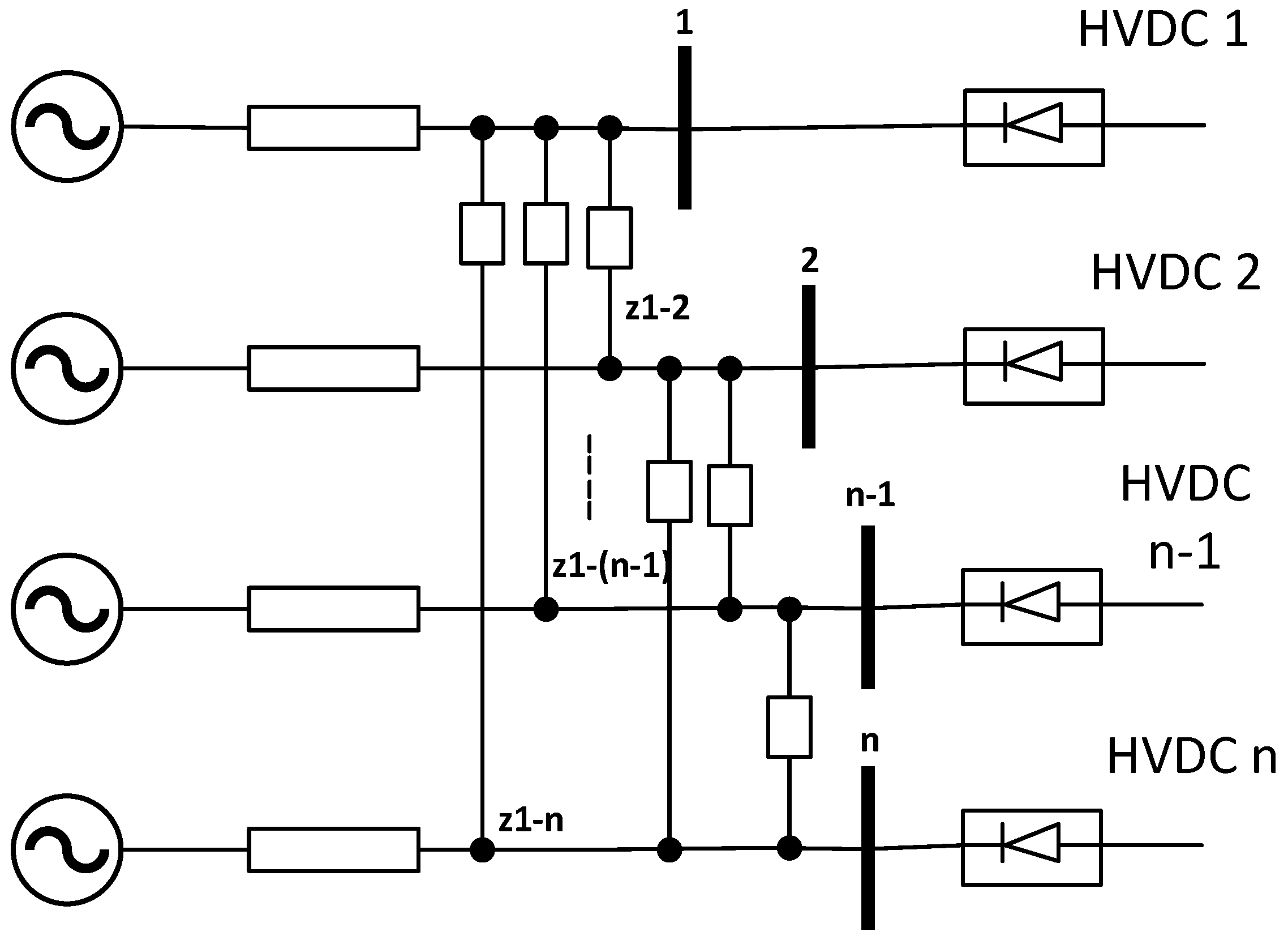
2.1. Multi-Infeed Schemes

The trend of installing HVDC for bulk power transmission is increasing with every passing year. Situations are occurring, such as in the southeast coast of China, where several HVDC links are installed to meet the industrial load. The existence of more than one HVDC link in a close area initiates a new configuration termed “multi-infeed HVDC”. MI-HVDC raises new challenges because the working of each converter is disturbed by other converters in proximity. Therefore, MI-HVDC has received much attention in recent research. There are three main configurations of MI-HVDC systems [11].
(i).
Ring type;
(ii).
Chain type;
(iii).
Mesh type
The ring-type multi-infeed DC system is shown in Figure 1a. It is similar to a scheme where several HVDC links encircle a city and feed at a specific point. If two HVDC links feed a city (same AC system), then the schematic diagram will become as shown in Figure 1b. The schematic diagram in Figure 1b is often called dual-infeed HVDC system.
Chain-type multi-infeed HVDC systems can be imagined as shown in Figure 2. Here, the HVDC links lie in close vicinity and have very short electrical distance. In a chain-type MI-HVDC system, the HVDC converters do not have direct connection, but they are connected via nearby links. Another possible structure of the MI-HVDC system can be formed as in Figure 3. The configuration is a meshed network where several HVDC links feed at various buses in the network. This structure is more complex than previous and commonly found structures in the Southern Power Grid of China.

2.2. Fundamental Indices Developed for a Multi-Infeed LCC–HVDC System

The multi-infeed interaction factor (MIIF) is an important quantitative index to determine the closeness between two converters in a multi-infeed scenario. The MIIF was first reported in [12] and later in [13]. It estimates the degree of voltage interaction between converters’ AC buses. The MIIF21 from converter 1 to converter 2 is actually the ratio of voltage change at converter 2 to voltage change at converter 1 caused by an injection of reactive power at converter 1. A 1% voltage change is recommended to calculate the MIIF. It is suggested in [14] that an MIIF of less than 0.15 between two converters means that the interaction is quite small, and the multiple DC systems can be considered a single infeed. Furthermore, if the MIIF ranges between 0.15 and 0.40, then the interaction is moderate, and if the MIIF is greater than 0.4, then the multi-infeed system has strong interaction between converters’ AC bus voltages. Converters with high power rating affect more compared with low-rating converters, and converters with low power rating influences less compared with high-power-rating converters in a multi-infeed configuration.
The CIGRE report [14] discusses the multi-infeed HVDC systems in detail. The report discusses the MIIF between converters. It provides bases to cop various transient and steady-state phenomena of multi-infeed HVDC systems. It is given that if the MIIF is zero, then all HVDC systems in close proximity will behave as a single infeed HVDC system, and if the MIIF is 1, then the all HVDC systems in a multi-infeed scenario will operate as they are connected to the same AC bus.
Single-infeed HVDC systems use a fundamental indicator to assess the strength of an AC system to which the HVDC is connected. This index is called short circuit ratio (SCR). It is basically the ratio of the short circuit level of the HVDC link at the commutation bus to the power rating of the HVDC link. The installed reactive power support at the HVDC commutating bus disturbs the system strength at the fundamental frequency. Consequently, the effective short circuit ratio (ESCR) index is introduced to overcome the filter’s response at a fundamental frequency. This index is actually calculated by subtracting the total reactive power at the commutation bus from the short circuit level of the HVDC link and then taking the ratio to the rated power of the HVDC. The stronger the AC system is, the higher is the short circuit level, and subsequently, the better is the performance of the HVDC link. Mostly the HVDC link is planned for an ESCR higher than 2.0.
Multi-infeed scenarios have led to a new index called multi-infeed effective short circuit ratio (MIESCR). The traditional index was not sufficient enough to measure the strength of the multi-infeed configuration because it was unable to incorporate the nearby HVDC links in the system strength. The concept of multi-infeed short circuit ratio was first proposed in [15]. The concept then extended to various versions to incorporate all converters in proximity. This new index helped to investigate multi-infeed configurations because it results in actual system strength compared with previous indices, which produce optimistic results.
In single infeed HVDC systems, the power and voltage stability are characterized on the ESCR. If the effective short circuit ratio (ESCR) is less than critical value, then the voltage collapses. Similar concepts are being extended for multi-infeed configuration, but they are more complex because the MIESCR is always less than the ESCR of a single infeed HVDC system. The practical AC network between two converters of a multi-infeed HVDC system can be simplified as one impedance. It is also important to mention that a multi-infeed scenario with multiple converters has multiple MIIFs (as the MIIF exists in between any two converters).
Transient overvoltage occurs when a converter stops absorbing reactive power; temporarily, the converter fails to transfer active power. The excess amount of reactive power at the converter bus produces overvoltage. The worst transient overvoltage appears when all converters in proximity are simultaneously blocked due to maloperation or a fault. In most situations, the worst transient overvoltage is calculated by simultaneous commutation failure on all converters of a multi-infeed system. The transient overvoltage largely depends on the AC system strength; the percentage transient overvoltage reduces with an increase in system strength. Moreover, with an increase in system damping angle, the transient overvoltage decreases. The multi-infeed scenario also affects the transient overvoltage because as the MIIF increases, the system strength decreases, which ultimately increases the transient overvoltage.

3. Voltage Stability of a Multi-Infeed LCC–HVDC System

The literature shows two approaches for addressing the stability of a multi-infeed HVDC (i.e., the maximum-achievable-DC-power-based approach and voltage-stability-factor-based approach).

3.1. Maximum Available Power (MAP)

In the maximum achievable power (MAP)-based approach, the maximum DC power achieved by an inverter at a constant extinction angle is taken as the stability limit [16]. For this reason, the maximum power curve (MPC) is observed, and the system strength at the maximum point is said to be the critical system strength. An analysis of MAP is provided in [17]. For MAP, only the direct current is varied, and the other parameters are kept constant. If the direct current is further increased at the MAP point, the maximum achievable power decreases. The power derivative with respect to the direct current is used as an index to assess stability. If the derivative is positive, the system is stable, and if the derivative is negative, then it will cause a reduction in DC power.

3.2. Voltage Stability Factor (VSF)

The voltage-stability-factor-based approach was initially proposed in [18]. It computes the ratio between changes in voltage to the varying reactive power injection. This ratio is named voltage stability factor (VSF). A system is said to be stable if the VSF is small and positive. The increasing value of the VSF indicates that the system is losing stability. The system moves to an unstable region when the VSF becomes infinite. On the other hand, if the VSF is negative, then the system is also unstable. The correlation between MAP- and VSF-based approaches is first reported in [19]. It is investigated that at the maximum of the MPC, the VSF becomes infinite for inverters operating at a constant extinction angle (CEA).
In ref. [20], it is reported that the power flow Jacobian has great influence on the voltage stability of a power network. If the Jacobian of the power network is becoming singular, the power system is losing its stability and operates with less stability margin. This opens new directions in the field of power system stability. In ref. [21], the voltage stability analysis for multi-infeed HVDC is discussed using the eigenvalue-based approach. The eigenvalues of a reduced Jacobian matrix are inverse of the VSF. In ref. [22], a method is presented to estimate the voltage stability by decomposing the Jacobian matrix into eigenvalues at steady-state conditions. The bus angle is decoupled by assuming ΔP = 0, which means no active power injection [23]. The Jacobian matrix turns to the reduced Jacobian matrix by considering ΔP = 0, which only shows the influence of reactive power on the stability of the AC/DC power system. The reduced Jacobian matrix can easily be decomposed into eigenvalues by using a modal analysis [22]. The reactive power injection (ΔQ) and change in bus voltage (ΔV) are related by eigenvalues. For voltage stability, all eigenvalues must be positive. The relationship between Q and V is in-phase if the eigenvalues are positive and antiphase if the eigenvalues are negative. The in-phase relation corresponds to a stable operation, as the bus voltage increases with an increase in reactive power. The antiphase relation indicates an unstable operation; the bus voltage decreases as the reactive power is injected. Similarly, when eigenvalues become zero, the reduced Jacobian becomes singular, and a tiny change in reactive power leads to an infinite change in bus voltage. This also corresponds to an unstable operation. The HVDC system is modelled as described in [24]. The converters in a multi-infeed scenario are connected via coupling impedance. Each converter is occupied with reactive power support by installed filters and static capacitors. All converters in multi-infeed are normalized on a common base. The Thevenin impedance of each AC system to which the HVDC is connected and the coupling impedance greatly affect the system stability.
An equivalent single infeed model of a multi-infeed HVDC system is proposed in [25]. The voltage stability using equivalent nodal analysis is discussed in [26]. The method considers N node, L load, and M generator buses to compute an equivalent model. The impact of a control system on voltage stability is investigated in [27]. The linearized equations are used to model the modal analysis of a multi-infeed HVDC system. It is also reported that both active and reactive powers influence the voltage stability, but in order to simplify the equations, only the reactive power injection is considered.
The modal analysis for voltage stability considering the point of collapse is reported in [28]. It is discussed that the modal analysis can be applied to a power system to evaluate the vulnerability of voltage stability. Modal analysis results in an appropriate location for installing reactive power support. The modal analysis can judge the system behavior for stability only in case of incremental change. A computer program for estimating the small signal stability of a power system is described in [29].
The power stability concept about a single infeed HVDC system is discussed in [19]. The same concept is extended for multi-infeed HVDC in [30]. The concept uses the MPC technique and eigenvalue decomposition method to analyze the power stability. The MPC method provides only a single degree of freedom to control the stability, whereas the eigenvalue-based technique gives more freedom to control the system stability by using various parameters. To get a mathematical model relating the DC power and direct current of a multi-infeed system, it is assumed that no active and reactive powers are injected. Only the DC power is considered, which converts the AC/DC Jacobian matrix to a DC-power-DC-current-reduced Jacobian matrix. The MAP of each converter in a multi-infeed HVDC system is obtained by taking the parameters of all other converters as constant. The DC power and DC current would be in-phase for a positive eigenvalue and vice versa. Hence, for a stable DC power, the eigenvalue of the DC-power-DC-current-reduced Jacobian matrix must be greater than zero.

4. Commutation Failure (CF) in a Multi-Infeed LCC–HVDC System

Commutation failure (CF) in single and multi-infeed HVDCs is an adverse event, which occurs due to the failure of current transfer from one valve to the next in a pattern. The main reason for CF is the reduction in the commutating voltage of a converter due to any significant fault at the converter’s commutating bus or near the converter. It might occur due to rapid increase in DC current, voltage waveform shift, harmonics, and maloperation of a control system. CF can cause a temporary suspension of power transfer to AC networks. Practically, the normal operation of a HVDC system includes switching of several thyristors in a predefined manner. If any of the thyristors keep on conducting in their blockage period, then the two phases of a converter transformer create a short circuit. This transformer’s short circuit results in the temporary suspension of power transfer to an AC network.
In an LCC–HVDC system, the converter station needs a large amount of reactive power during commutation failure. If sufficient reactive power support is not available, the converter moves to a blockage stage. In case of a multi-infeed configuration, if sufficient reactive power supply to a converter station is not available, then the decrease in bus voltage influences the nearby converter’s bus voltage, which can ultimately cause commutation failure at a remote converter. In order to mitigate commutation failure, different compensators, such as static synchronous compensator (STATCOM), synchronous condenser (SC), and static VAR compensator (SVC), are linked to the converter’s bus [31]. In real-world HVDC projects, a STATCOM and SC are usually connected at an inverter’s end in order to improve the voltage profile and reduce the chances of commutation failure under single and three-phase AC faults.
The commutation failure is also influenced by the AC system’s strength. The higher is the AC system’s strength, lesser will be the chances of commutation failure in a converter station and vice versa. In a single infeed LCC–HVDC system, a higher short circuit ratio (SCR) of the AC system results in lower commutation failure. In the case of a multi-infeed LCC–HVDC system, a higher multi-infeed effective short circuit ratio (MIESCR) indicates a lower risk of commutation failure in a converter station. It can be noted that if the voltage interaction between converters is high and no reactive power compensator is installed at any of the converter buses, then there is a greater chance that commutation failure in one converter can cause CF in the neighborhood converter station.
In an LCC–HVDC system, harmonics are produced at the DC and AC sides. The harmonics interaction between converters is a quite complex phenomenon. Despite the voltage interaction, the harmonics interaction may also cause commutation failure at a remote converter. The harmonics interaction reduces the voltage time area to remove the charges stored in forward conduction. The harmonics also distort the voltage waveform and shift the zero crossing to the left, providing less time to valves for ignition. The famous anomalous commutation failure happens due to this harmonics interaction. In an anomalous commutation failure, commutation failure occurs for faults of less severity. The postcommutation failure converter blocking scheme and strong AC system may result in less harmonics interaction between converters. It is reported that converters with a multi-infeed interaction factor (MIIF) of less than 0.1 virtually have no chance of harmonics interaction.
The multi-infeed scenarios have made the commutation process more complex due to interconverter interactions. Commutation failure at one converter may cause commutation failure at other converters in proximity. This leads to a new concept of concurrent commutation failure. A concurrent commutation failure depends on the MIIF between any of two converters. If the interaction is strong, then there is a vast possibility that a local commutation failure may cause commutation failure at a remote converter. Thus, a fault on a local bus causing commutation failure at a local converter is termed local commutation failure, while a fault on a local bus causing commutation failure at a remote converter is termed concurrent commutation failure. In a multi-infeed HVDC system, remote commutation failure by a fault at a local bus is also caused by post commutation failure converter interaction. It means that a fault does not directly cause commutation failure at a remote converter; rather, it is the interaction between converters that distorts the voltage waveform, reduces the voltage, and shifts the zero crossing. Therefore, the harmonic content in a commutating voltage is also a major reason causing concurrent commutation failure.
The two important aspects of commutation failure are commutation failure susceptibility of any HVDC link and recovery from commutation failure. Both these parameters depend on AC/DC system strength and control. It might happen that a system is more prone to commutation failure, but it is capable of recovering fast. At the same time, a system might be less susceptible to commutation failure but does not have the ability to recover fast from failure. Initially, commutation failure was assessed by the stability limits of the HVDC system. For multi-infeed DC systems, the transient behavior affects the occurrence of commutation failure. Thus, transient programs with a detailed modeling of generators, HVDC converters, valves, transformers, and control are encouraged to measure the susceptibility of commutation failure. The indices MIIF, MIESCR, and allied norms are a great reflection of commutation failure immunity.
A few methods for detecting commutation failure are:
  • Calculating the maximum acceptable voltage drop;
  • Electromagnetic transient (EMT) program;
  • Examining the valve conduction status;
  • Comparing the valve current with a DC current;
  • Estimating the AC current of all phases of a transformer;
  • Inspecting the DC current of a converter;
  • Observing the extinction angle
The analytical method for computing commutation failure was first discussed in detail in [32]. During the conduction of a converter valve, the valve stores changes. These charges need a proportion of time to remove before going to a blocking period. Therefore, a significant voltage time area is required, named commutation margin angle. As commutation failure often occurs due to AC voltage reduction because of a fault or disturbance, which is unavoidable, the magnitude of a sudden voltage drop needs to be evaluated, which can initiate commutation failure. It is assumed that the DC current and extinction angle remain constant when a commutating voltage suddenly collapses. This leads to the same voltage time area. However, the overlap angle increases, reducing the extinction angle. This means that the commutation process extends to a new extinction angle. The formula developed calculates the maximum acceptable voltage drop that does not cause commutation failure. If a fault produced a voltage drop higher than the permissible limit, then commutation failure was supposed to occur. The formula was derived using steady-state equations of an HVDC converter. It is assumed that a voltage source is ideal, and a control system does not act during disturbance. This formula yields poor calculation of commutation failure susceptibility. An electromagnetic transient (EMT) simulation-based technique is reported in [13] to calculate commutation failure immunity. Commutation failure in HVDC is detected with several techniques. Some techniques even directly check the valve conduction status. A few methods detect commutation failure by examining the current flow in valves. A method comparing the valve current with the DC current is also reported in the literature. The AC current of all phases of a transformer drops to zero during commutation failure, and the DC current exceeds the threshold. The absolute sum of the current in all phases of a transformer becomes less than double of the DC current. This indicates commutation failure in an HVDC converter. For the CIGRE benchmark model, the normal extinction angle is 15°. An extinction angle of 7° is considered to be a critical extinction angle. Below 7°, commutation failure occurs. The fault level that reduces the extinction angle to 7° is named critical fault. The fault above the critical level causes commutation failure. The ideal critical value for commutation failure is 0°, but for practical projects, it is calculated to be 7°, providing a sufficient voltage time area to remove charges. The extinction angle method for detecting commutation failure only estimates the critical fault level. It ignores transient affects, such as phase shift, harmonics, and DC current change. These transient phenomena influence the commutation failure probability [33]. The steady-state method results in optimistic values of the voltage level, which cause commutation failure, while the transient technique yields an accurate value of voltage, which is higher than the steady-state value for commutation failure. This means that a steady-state value indicates that commutation failure will occur for a very low value of voltage, but in actuality, it is not the case. Commutation failure, in the transient technique, occurs for a higher value of voltage than the value that the steady state predicted. The difference is due to the aforementioned facts.
Commutation failure analysis using an electromagnetic transient program needs a term (index) to find a critical fault value that does not cause commutation failure. This leads to the introduction of the commutation failure immunity index (CFII). The CFII is based on the minimum value of inductance that does not cause commutation failure. This corresponds to the ratio of the worst critical fault MVA level to the rated DC power of a converter. Similar to local and concurrent commutation failure, a local CFII determines the immunity of a local converter, and a concurrent CFII estimates the immunity of a remote converter to a local fault. The MIIF plays a vital role in the occurrence of concurrent commutation failure. The MIIF is influenced by the AC system strength of each converter in a multi-infeed configuration. Thus, concurrent commutation failure indirectly depends on the AC system strength of converters in proximity. The concurrent CFII is inversely proportional to the MIIF. This means that a low value of the MIIF corresponds to a higher value of the concurrent CFII. It is discussed in [14] that if the MIIF is less than 0.3, concurrent commutation failure would not be a serious issue. Similar to single infeed, in multi-infeed HVDC systems, recovery from commutation failure depends on the MIESCR. The higher is the MIESCR, the faster is the recovery. A single commutation failure does not have a destructive nature. Although a single commutation failure disturbs power quality, it does not have too much effect on system stability. If commutation failure occurs more frequently, it will definitely be a challenge for system planners and a great threat to system stability. Frequent commutation failure in a single infeed HVDC system is a most harmful event. Similarly, frequent commutation failure in a multi-infeed HVDC system is a great reason for system instability and energy loss. The impact of frequent commutation failure in multi-infeed DC systems is much more destructive than in a single infeed system. Several precautions are described to reduce the commutation failure frequency, such as reducing the interaction factor, using a large smoothing reactor, and increasing the extinction angle.
In ref. [34], a detailed analysis of commutation failure in multi-infeed HVDC is presented. The AC system is modeled as an equivalent Thevenin impedance and a corresponding voltage source. The Thevenin impedance has a great impact on the overvoltage and commutation failure of an HVDC system [35]. The Thevenin impedance is calculated by looking into an AC system from a converter bus. If the MIIF between converters is less than 0.15, then each HVDC system in a multi-infeed scenario can be considered a single infeed system. In order to calculate the ESCR at a converter, all other converters in proximity are assumed to be blocked. This assumption leads to optimistic results because even the converter is blocked, but the nearby AC system is still intact with a local HVDC system. The drawbacks of a maximum permissible voltage drop formula are also discussed because the formula uses a steady-state calculation method that ignores the transient behavior of an HVDC system. This is why the maximum permissible voltage drop method for judging commutation failure sometimes gives a wrong measure of commutation failure susceptibility. The CFII approach described in [13] is used to assess the immunity of a converter to commutation failure. The most severe fault (i.e., three-phase inductive fault) is considered in the derivation of an immunity index. Commutation failure depends on the fault level and the time at which the fault is applied. It is reported in [36] that commutation failure depends not only on fault severity but also on the time instant at which the fault is induced. The CFII is independent of the time instant on the wave at which the fault occurs. The CIGRE benchmark model is investigated to have a commutation failure immunity of 13.3% at the short circuit level (SCL). PSCAD/EMTDC (an electromagnetic transient program) uses an interpolation technique between samples, and hence, the output results are no longer sensitive to a simulation time step [37]. Commutation failure mainly occurs due to AC side disturbance, but DC side inductance (smoothing reactor) also influences commutation failure. For the CIGRE benchmark model, the DC side inductance is 1.194 H cumulatively. The change in DC side inductance affects the CFII.
In multi-infeed HVDC systems, generally the source impedance and coupling impedance are varied to get the desired MIIF and AC system strength in EMT simulations. The local CFII is reported to be independent of the MIIF and remote HVDC converter parameters [13]. This results in favorable values of the local CFII. Several scenarios are discussed in relation to concurrent commutation failure in the literature. The first scenario is analysis of concurrent commutation failure with a local converter permanently blocked. This scenario gives the impact of an AC network on concurrent commutation failure, as the local converter is blocked, so it does not have an effect on a remote converter. However, the coupling impedance and AC system strength have a significant part in concurrent commutation failure. The second scenario investigates concurrent commutation failure when a local converter is blocked after local commutation failure. This avoids post-local commutation failure interaction between converters. As a result, the chances of concurrent commutation failure are reduced. The third scenario estimates concurrent commutation failure when there is no scheme to block a local converter. This means that both converters remain in operation after commutation failure. This leads to the most severe interaction between converters, and hence, the chances of concurrent commutation failure increase. The CFII in case 3 is much less than in case 2. This is due to the fact that after commutation failure, a local converter disturbs the commutating voltage of a remote converter. Another phenomenon is reported, termed anomalous commutation failure. The commutation failure for faults of low severity instead of high severity due to distortion of a commutating voltage waveform is anomalous commutation failure.
In ref. [34], it is also discussed that for faults of less severity, the zero crossing of a commutating voltage moves left, resulting in a decreased commutation margin. In such cases, the voltage due to a fault is less depressed, but the commutation margin decreases because of the left shift. The insufficient voltage time area leads to commutation failure. This kind of commutation failure happens due to the advancement of a valve commutating voltage, not due to a reduction of voltage magnitude. The reason behind this anomalous commutation failure is harmonic content. The commutation voltage waveform for less severe faults is found to be more distorted than for severe faults. Therefore, concurrent commutation failure for less severe faults occurs due to a distortion in the voltage waveform, and for severe faults, it occurs due to the sudden depression of the voltage magnitude. If a post-commutation failure converter blocking scheme is used, anomalous commutation failure can be avoided. A few categories are reported, depending on the MIIF. If the MIIF is less than 0.06, then a remote converter does not have influence on local faults. If the MIIF is greater than 0.06 and less than 0.15, the local fault may cause remote commutation failure, but it does not have influence on a local converter block or unblock state. If the MIIF is greater than 0.15 and less than 0.6, the CFII is almost inversely proportional to the fault level. If the MIIF is greater than 0.6, every fault at a local converter will cause commutation failure at a remote converter. This corresponds to a constant fault severity because the voltage coupling between converters is too strong.
In ref. [38], it is discussed that a high local effective short circuit ratio reduces the likelihood of local commutation failure, and a higher MIIF increases the risk of concurrent commutation failure. Minimum-extinction-angle-based critical values are derived to quickly judge local and concurrent commutation failure. In ref. [39], the evolutional line commutation converter with a thyristor-based full-bridge module is discussed to detect and reduce commutation failure phenomena in single and multi-infeed HVDC systems. In the topology, a thyristor-based full-bridge module is connected in series with each valve of six pulse bridges. A predictive control strategy is proposed in [40] to reduce the chances of commutation failure. The strategy decreases the firing angle on the detection of a fault incident. A phasor measurement unit (PMU) is used to measure the Thevenin impedance. As the Thevenin impedance seen from an inverter bus decreases when the fault occurs, the fault severity and firing angle are estimated based on this Thevenin impedance. An approach for detecting commutation failure based on fault distance from a converter is discussed in [41]; it uses a minimum-extinction-angle-based approach to judge the susceptibility of commutation failure. A fuzzy-controller-based approach to advance the firing angle in the detection of commutation failure is proposed in [42]. A technique for controlling the direct current during a fault is provided in [43]. A capacitor modulation technique for minimizing the commutation failure in a line-commutated converter is discussed in [44]. A power-component-based fault detection method for eradicating the chances of commutation failure is discussed in [45].

5. DC Interaction of a Multi-Infeed LCC–HVDC System

With increasing scenarios of multi-infeed HVDC, vast research has been conducted on the steady-state and transient behavior of AC/DC systems. A few multi-infeed phenomena, such as multi-infeed harmonics analysis, multi-infeed power flow, and multi-infeed direct current interaction, have a lack of literature. However, for a single infeed HVDC system, a direct current interaction with an AC system is discussed in [46]. The analysis is made based on the assumptions of an inverter feeding to a weak AC system, steady-state operation before malfunction, and no voltage control scheme is applied. The converter bus voltage following a variation in DC current undergoes change and obtains another steady-state value. The bus voltage increases to a new steady-state value in response to a step reduction in DC current. The variation in voltage is actually caused by imbalanced reactive power support. An attempt to model multi-infeed direct current interaction is given in [47]. It uses the mathematical power flow model to derive various indices about multi-infeed HVDC systems. Most importantly, it derives the MIIF using a power flow approach, which is analytically equivalent to a conventional MIIF. The conventional MIIF is based on empirical information, which does not have a rigorous theoretical background. The theoretical framework discussed can help to investigate voltage and power instability. The study also provides basics to probe the insight behavior of voltage and power interaction between converters. The AC side Jacobian matrix is reduced to get the nodal voltage interaction factor, which is equivalent to the MIIF. The incremental reactive power change at only one bus is considered; the reactive power change at other converters’ bus is assumed to be zero. This yields two indices, the nodal voltage sensitivity factor and the nodal voltage interaction factor. The nodal DC power and DC current indices are also discussed. The AC/DC power flow Jacobian matrix is reduced with ΔP = 0 and ΔQ = 0; only the change in DC power is assumed. All the converters in a multi-infeed configuration are assumed to be in a constant DC power and constant extinction angle control mode. The nodal current interaction factor is derived as the ratio of change in current at the jth converter to change in current at the ith converter in response of power change at the ith converter.

6. AC/DC Power Flow of a Multi-Infeed LCC–HVDC System

The power system is a mesh network between generating plants and consumers. A power (load) flow study is a method for analyzing the flow of power numerically in a complex interconnected system. Power flow analysis computes various key parameters in a steady-state environment, such as real power, reactive power, voltage magnitude, and angle. Power flow analysis is very important for the planning and expansion of a power network. Load flow analysis gives the strength of a power system to supply power to connected loads. An adequate transformer tap position is selected to provide a scaled voltage to load. The power flow problem is highly nonlinear. Thus, numerical methods are employed to get a solution within acceptable tolerance. Before applying any technique, a number of unknowns are identified. Similarly, the buses are classified into slack bus, load bus, and generator bus. At the load bus, real and reactive powers are given. At the generator bus, real power and voltage magnitude are given. The slack bus is a reference bus with a known voltage and its angle. Power balance equations are derived to compute unknown parameters. There are a number of methods for solving nonlinear power flow equations, such as Newton–Raphson, Gauss–Seidel, fast decoupled, and holomorphic embedding. Among these methods, the Newton–Raphson method is very much famous due to its fast convergence ability and simplicity. The Newton–Raphson method uses the Taylor series to get approximate linear equations of a nonlinear power system by ignoring the higher orders. The Newton–Raphson power flow method has been used in a power system for a long time.
Power flow analysis is essential in order to plan new systems and get the critical operating conditions of an existing power network [48]. With the introduction of a DC transmission technology, the conventional AC power flow term has turned into an AC/DC power flow. The two most important methods for solving an AC/DC system are simultaneous and sequential approaches [49]. In a simultaneous approach, the DC equations describing its power, voltage, and current relation, including control parameters, are solved in combination with AC system equations. The sequential approach solves both AC and DC systems separately by using interface variables, which link these two systems. The sequential approach is easy to program and is widely used in an AC/DC interconnected power system. In ref. [50], a unified (simultaneous) approach is discussed to compute the AC/DC power flow by incorporating reactive power devices.
The purpose of an AC/DC power flow solution is to find unknown parameters for rated values of known parameters. The parameters for a DC system are extinction angle, converter tap position, AC bus voltage (interface variable), and AC bus voltage angle (interface variable). An application of a sequential approach is given in [51], and an application of a unified (simultaneous) approach is explained in [52].
An approach for AC/MTDC power flow is discussed in [53]. The method presented replaces a DC system with an equivalent voltage depending on the load and deploys the fast decoupled method to solve power flow equations. A load flow analysis for hybrid AC/DC systems with distributed energy resources is reported in [54]. The analysis uses a sequential approach with the Newton–Raphson method by incorporating converter losses. A sequential approach to the power flow of voltage-source-converter-based multiterminal DC systems is presented in [55]. The load flow using the Gauss–Seidel method of an integrated AC/DC network is discussed in [56]. The method uses a sequential approach with DC systems as the current injecting source at a converter bus. A solution to the AC/DC power flow problem of multiterminal HVDC systems with a sequential and Gauss–Seidel approach is discussed in [57]. A fundamental work in an AC/DC power flow is reported in [58]. The work provides insight information on both sequential and simultaneous techniques. AC and DC systems are properly modeled. The specific control parameters are also considered for the fast decoupled power flow method. In ref. [59], a converter modeling for a simultaneous approach of power flow is explained. The converter buses are modeled as a constant-voltage-depended load. A problem associated with a converter tap position is discussed in [60]. The converter tap position in a power flow is a very essential parameter for convergence. Mostly, the tap position obtained lies outside the gear limit, and sometimes it makes an extinction angle to hit its limits. In all the available literature, the obtained tap position is continuous and turns discrete by regulating to the nearest discrete value. This technique initiates an error in other control parameters of a converter, especially the converter’s extinction angle. An improved AC/DC continuous power flow method for stability and point of collapse is discussed in [61]. A technique describing a power flow method of AC and multiterminal DC systems is investigated in [62]. The DC converters are modeled as a current source in parallel with commutating resistance.
A detailed analysis of an AC/DC power flow considering multi-infeed HVDC systems is reported in [63]. The advantages and disadvantages of both sequential and simultaneous approaches are highlighted in detail. The simultaneous approach does not have the ability to use existing AC power flow programs. The reason is obvious that the AC and DC systems in a simultaneous approach are solved together, which increases the size of calculations and also increases the complexity. The benefits of a sequential approach are much more than those of a simultaneous approach because the sequential approach has the ability to use existing programs of an AC power flow. All that has to be done is to integrate existing programs with new DC power flow methods. Moreover, due to a separate solution for both systems, the complexity of calculation also decreases. The sequential method is widely accepted in a power flow analysis of AC/DC systems, but it also has some challenges. Specifically, the sequential approach encounters a convergence issue when a DC system operates under reduced power. To deal with imaginary reactive power, the cosine of an extinction angle and a tap adjustment problem, a method is discussed that changes the state variables. The discrete value of a converter tap position is achieved by regulating to nearest discrete gear. In ref. [64], the AC/DC power flow for multiterminal HVDC systems is discussed by including the DC network. The method uses the simultaneous power flow approach, which extends the size of the Jacobian matrix and the complexity. A generic DC network representation is provided by considering the independent current source at each node. The converter transformer tap positon adjustment problem remains unaddressed for quick convergence.

7. Analytical Expression and Parameter Specification of a Multi-Infeed LCC–HVDC System

This section provides a few fundamental formulas of HVDC in a multi-infeed scenario (Table 1) and a simplified chain-type multi-infeed HVDC model (Figure 4) used in the literature for local and concurrent commutation failure studies. The parameters used in Figure 4 are explained in Table 2. The legends of the symbols used in Table 1 are presented in Table 3.

8. Conclusions

This paper provides a comprehensive review of the literature available on voltage stability, commutation failure, DC interaction, and power flow of multi-infeed LCC–HVDC. The increasing penetration of HVDC in modern power systems has turned into a situation where several HVDC links exist in close electric vicinity. Such multi-infeed scenarios face several challenges compared with conventional single infeed DC systems. The interaction between converters makes the operation of such systems more complex and raises issues regarding stability, local and concurrent commutation failure, AC/DC interaction, and power flow. The AC system strength of a multi-infeed HVDC system is found to be less than that of a single infeed DC system because of interconverter interaction. This interconverter interaction is measured by the MIIF. The maximum available power (MAP)- and voltage stability factor (VSF)-based approaches for investigating the stability of an AC/DC system are explained. The MAP-based approach provides a single degree of freedom (i.e., direct current) to designers, while the VSF-based approach using eigenvalues gives more control to system planners for stability. A detailed analysis of local and concurrent commutation failure is provided. It is explained how the MIIF affects concurrent commutation failure in a multi-infeed scenario. The methods for judging commutation failure are explained. The assumptions and drawbacks of each approach are also highlighted. The AC/DC power flow approaches and problems are also described in detail. The detailed review and analysis in this paper can be used as a technical guide for future research.

Author Contributions

The authors equally contributed to this research work. All authors have read and agreed to the published version of the manuscript.

Funding

The authors acknowledge the financial support from the Basic Science Research Program through the National Research Foundation of Korea funded by the Ministry of Education (2016R1D1A1B01008058). This work was supported by the Human Resources Development (No.20204030200090) of the Korea Institute of Energy Technology Evaluation and Planning (KETEP) grant funded by the Korea government Ministry of Trade, Industry and Energy.

Institutional Review Board Statement

Not applicable.

Informed Consent Statement

Not Applicable.

Data Availability Statement

Not Applicable.

Acknowledgments

The authors acknowledge the financial support from the Basic Science Research Program through the National Research Foundation of Korea funded by the Ministry of Education (2016R1D1A1B01008058). This work was supported by the Human Resources Development (No.20204030200090) of the Korea Institute of Energy Technology Evaluation and Planning (KETEP) grant funded by the Korea government Ministry of Trade, Industry and Energy.

Conflicts of Interest

The authors declare no conflict of interest.

References

  1. Long, W.; Nilsson, S. HVDC transmission: Yesterday and today. IEEE Power Energy Mag. 2007, 5, 22–31. [Google Scholar] [CrossRef]
  2. Cole, S.; Belmans, R. Transmission of bulk power. IEEE Ind. Electron. Mag. 2009, 3, 19–24. [Google Scholar] [CrossRef]
  3. Rehman, B.; Liu, C. A Generalized N Terminal Current Order Control Scheme for LCC MTDC. In Proceedings of the IEEE 2nd International Electrical and Energy Conference (CIEEC), Beijing, China, 4–6 November 2018; pp. 344–349. [Google Scholar]
  4. Arrillaga, J. High Voltage Direct Current Transmission, 2nd ed.; Johns, A.T., Warne, D.F., Eds.; The Institution of Engineering and Technology: London, UK, 1998; ISBN 9780852969410. [Google Scholar]
  5. Rehman, B.; Liu, C. AC/DC Multi-Infeed Power Flow Solution. IET Gener. Transm. Distrib. 2019, 13, 1838–1844. [Google Scholar] [CrossRef]
  6. Lips, H.P. Aspects of Multiple Infeed of HVDC Inverter Stations into a Common AC System. IEEE Trans. Power Appar. Syst. 1972, 92, 775–779. [Google Scholar]
  7. Reeve, J.; Lane-Smith, S.P. Multi-Infeed HVDC Transient Response and Recovery Strategies. IEEE Trans. Power Deliv. 1993, 8, 1995–2001. [Google Scholar] [CrossRef]
  8. IEEE Power & Energy Society. IEEE Guide for Planning DC Links Terminating at AC Locations Having Low Short-Circuit Capacities; IEEE Standard Board: New York, NY, USA, 1997; pp. 1–216. [Google Scholar]
  9. Krishnayya, P.C.S.; Piwko, R.J.; Weaver, T.L.; Bahrman, M.P.; Hammad, A.E. DC Transmission Terminating at Low Short Cirucit Ratio Locations. IEEE Trans. Power Deliv. 1986, 1, 308–318. [Google Scholar] [CrossRef]
  10. Gavrilovic, A. AC/DC system strength as indicated by short circuit ratios. In Proceedings of the International Conference on AC and DC Power Transmission, London, UK, 17–20 September 1991; pp. 27–32. [Google Scholar]
  11. Aik, D.L.H.; Andersson, G. Voltage and Power Stability of HVDC Systems—Emerging Issues and New Analytical Methodologies. In Proceedings of the VII Symposium of Specialists in Electric Operational and Expansion Planing (SEPOPE), Curitiba, Brazil, 23–28 May 2000; pp. 1–10. [Google Scholar]
  12. Rahimi, E.; Gole, A.M.; Davies, J.B.; Fernando, I.T.; Kent, K.L. Commutation Failure and Overvoltage Phenomena in Multi-Infeed HVDC Systems. In Proceedings of the Colloquium of Role of HVDC, FACTS and Emerging Technologies in Evolving Power Systems, Bangalore, India, 23–24 September 2005; pp. 54–73. [Google Scholar]
  13. Rahimi, E.; Gole, A.M.; Davies, J.B.; Fernando, I.T.; Kent, K.L. Commutation Failure in single- and multi-infeed HVDC systems. In Proceedings of the IEEE International Conference on AC and DC Power Transmission, London, UK, 5 June 2006; pp. 182–186. [Google Scholar]
  14. Davies, B.; Williamson, A.; Gole, A.M.; Ek, B.; Long, B.; Burton, D.K.; Brandt, D.; Lee, D.; Rahimi, E.; Andersson, G.; et al. Cigré; WG B4.41; Publication 364: Paris, France, 2008; pp. 1–118. [Google Scholar]
  15. De Toledo, P.F.; Bergdahl, B.; Asplund, G. Multiple Infeed Short Circuit Ratio—Aspects Related to Multiple HVDC into One AC Network. In Proceedings of the IEEE/PES Transmission & Distribution Conference & Exposition: Asia and Pacific, Dalian, China, 5 December 2005; pp. 1–6. [Google Scholar]
  16. Ainsworth, J.D.; Gavrilovi’c, T.H. Static and Synchronous Compensators for DC Transmission Converters Connected to Weak AC Systems. In Proceedings of the Cigre General Session, Paris, France, 31 January 1980. Paper 31. [Google Scholar]
  17. Zhang, X.; Chen, C. Maximum available power of multi-infeed hvdc system analysed by sensitivity method. IET Gener. Transm. Distrib. 2014, 8, 473–479. [Google Scholar] [CrossRef]
  18. Hammad, A.E.; Sadek, K.; Kauferle, J. A New Approach for the Analysis of and Solution of DC Voltage Stability Problems at HVDC Terminals. In Proceedings of the International Conference on DC Power Transmission, Montreal, QC, Canada, 4–8 June 1984; pp. 164–170. [Google Scholar]
  19. Franken, B.; Andersson, G. Analysis of HVDC converters connected to weak AC systems. IEEE Trans. Power Syst. 1990, 5, 235–242. [Google Scholar] [CrossRef]
  20. Tamura, Y.; Mori, H.; Iwamoto, S. Relationship between voltage instability and multiple load flow solutions in electric power systems. IEEE Trans. Power Appar. Syst. 1983, 102, 1115–1125. [Google Scholar] [CrossRef]
  21. Lee, D.; Aik, H.; Anderson, G. Voltage stability analysis of multi-infeed HVDC systems. IEEE Trans. Power Deliv. 1997, 12, 1309–1318. [Google Scholar]
  22. Gao, B.; Morison, G.K.; Kundur, P. Voltage stability evaluation using modal analysis. IEEE Trans. Power Syst. 1992, 7, 1529–1542. [Google Scholar] [CrossRef]
  23. Lof, P.A.; Hill, D.J.; Andersson, G. Analysis of Long Term Voltage Stability. In Proceedings of the 10th Power Systems Computation Conference, Graz, Austria, 1 January 1990; pp. 1252–1269. [Google Scholar]
  24. Szechtman, M.; Wess, T.; Thio, C.V. A Benchmark model for HVDC system studies. In Proceedings of the International Conferance on AC and DC Power Transmission, London, UK, 17–20 September 1991; pp. 374–378. [Google Scholar]
  25. Lee, D.H.A.; Andersson, G. An Equivalent Single-Infeed Model of Multi-Infeed HVDC Systems for Voltage and Power Stability Analysis. IEEE Trans. Power Deliv. 2016, 31, 303–312. [Google Scholar] [CrossRef]
  26. Lee, D.H.A. Voltage stability assessment using equivalent nodal analysis. IEEE Trans. Power Syst. 2016, 31, 454–463. [Google Scholar] [CrossRef]
  27. Wu, G.; Minakawa, T.; Hayashi, T. Modal Voltage Stability Analysis of Multi-Infeed HVDC System Considering Its Control Systems. IEEJ Trans. Power Energy 2006, 126, 776–782. [Google Scholar] [CrossRef] [Green Version]
  28. Pinto, H.J.C.P.; Martins, N.; Vieira, X.; Bianco, A.; Gomes, P.; dos Santos, M.G. Modal Analysis for Voltage Stability: Application at Base Case and Point of Collapse. In Proceedings of the Bulk Power Systems Voltage Phenomena III: Voltage Stability Security and Control, Davos, Switzerland, 22–26 August 1994; pp. 1–14. [Google Scholar]
  29. Kundur, P.; Rogers, G.J.; Wong, D.Y.; Wang, L.; Lauby, M.G. A comprehensive computer program package for small signal stability analysis of power systems. IEEE Trans. Power Syst. 1990, 5, 1076–1083. [Google Scholar] [CrossRef]
  30. Lee, D.; Aik, H.; Anderson, G. Power Stability Analysis of Multi-infeed HVDC Systems. IEEE Trans. Power Deliv. 1998, 13, 923–931. [Google Scholar]
  31. Saichand, K.; Padiyar, K.R. Analysis of voltage stability in multi-infeed HVDC systems with STATCOM. In Proceedings of the IEEE International Conference on Power Electronics, Drives and Energy Systems, Bengaluru, India, 16–19 December 2012; pp. 1–6. [Google Scholar]
  32. Thio, C.V.; Davies, J.B.; Kent, K.L. Commutation failures in HVDC transmission systems. IEEE Trans. Power Deliv. 1996, 11, 946–953. [Google Scholar] [CrossRef]
  33. Wang, F.; Liu, T.; Li, X. Decreasing the frequency of HVDC commutation failures caused by harmonics. IET Power Electron. 2017, 10, 215–221. [Google Scholar] [CrossRef]
  34. Rahimi, E.; Gole, A.M.; Davies, J.B.; Fernando, I.T.; Kent, K.L. Commutation Failure Analysis in Multi-Infeed HVDC Systems. IEEE Trans. Power Deliv. 2011, 26, 378–384. [Google Scholar] [CrossRef]
  35. Kundur, P. Power System Stability and Control, EPRI Power System Engineering Series; McGraw-Hill: New Delhi, India, 1994. [Google Scholar]
  36. Rahimi, E.; Filizadeh, S.; Gole, A. Commutation Failure Analysis in HVDC Systems Using Advanced Multiple-Run Method. In Proceedings of the IPST—International Conference on Power Systems Transients, Montreal, QC, Canada, 19–23 June 2005; pp. 19–23. [Google Scholar]
  37. Gole, A.M.; Fernando, I.T.; Irwin, G.D.; Nayak, O.B. Modeling of power electronic apparatus: Additional interpolation issues. In Proceedings of the International Conference on Power Systems Transients, Seattle, WA, USA, June 1997; pp. 23–28. [Google Scholar]
  38. Xiao, H.; Li, Y.; Zhu, J.; Duan, X. Efficient approach to quantify commutation failure immunity levels in multi-infeed HVDC systems. IET Gener. Transm. Distrib. 2016, 10, 1032–1038. [Google Scholar] [CrossRef]
  39. Guo, C.; Li, C.; Zhao, C.; Ni, X.; Zha, K.; Xu, W. An Evolutional Line-Commutated Converter Integrated with Thyristor-Based Full-Bridge Module to Mitigate the Commutation Failure. IEEE Trans. Power Electron. 2017, 32, 967–976. [Google Scholar] [CrossRef]
  40. Mirsaeidi, S.; Dong, X.; Tzelepis, D.; Mat Said, D.; Dysko, A.; Booth, C. A Predictive Control Strategy for Mitigation of Commutation Failure in LCC-Based HVDC Systems. IEEE Trans. Power Electron. 2018, 34, 160–172. [Google Scholar] [CrossRef] [Green Version]
  41. Yang, H.; Cai, Z.; Li, X.; Yu, C. Assessment of commutation failure in HVDC systems considering spatial-temporal discreteness of AC system faults. J. Mod. Power Syst. Clean Energy 2018, 6, 1055–1065. [Google Scholar] [CrossRef] [Green Version]
  42. Sun, Y.Z.; Peng, L.; Ma, F.; Li, G.J.; Lv, P.F. Design a fuzzy controller to minimize the effect of HVDC commutation failure on power system. IEEE Trans. Power Syst. 2008, 23, 100–107. [Google Scholar] [CrossRef]
  43. Wei, Z.; Yuan, Y.; Lei, X.; Wang, H.; Sun, G.; Sun, Y. Direct-current predictive control strategy for inhibiting commutation failure in HVDC converter. IEEE Trans. Power Syst. 2014, 29, 2409–2417. [Google Scholar] [CrossRef]
  44. Xue, Y.; Zhang, X.P.; Yang, C. Elimination of Commutation Failures of LCC HVDC System with Controllable Capacitors. IEEE Trans. Power Syst. 2016, 31, 3289–3299. [Google Scholar] [CrossRef] [Green Version]
  45. Guo, C.; Liu, Y.; Zhao, C.; Wei, X.; Xu, W. Power component fault detection method and improved current order limiter control for commutation failure mitigation in HVDC. IEEE Trans. Power Deliv. 2015, 30, 1585–1593. [Google Scholar] [CrossRef]
  46. Hatziadoniu, C.; Galanos, G.D. Interactions between the ac voltages and dc current in weak AC/DC interconnections. IEEE Trans. Power Deliv. 1988, 3, 2092–2102. [Google Scholar] [CrossRef]
  47. Aik, D.L.H.; Andersson, G. Analysis of voltage and power interactions in multi-infeed HVDC systems. IEEE Trans. Power Deliv. 2013, 28, 816–824. [Google Scholar] [CrossRef]
  48. Cheng, C.S.; Shirmohammadi, D. A three-phase power flow method for real-time distribution system analysis. IEEE Trans. Power Syst. 1995, 10, 671–679. [Google Scholar] [CrossRef]
  49. Fudeh, H.; Ong, C.M. A Simple and Efficient AC-DC Load-Flow Method for Multiterminal DC Systems. IEEE Trans. Power Appar. Syst. 1981, PAS-100, 4389–4396. [Google Scholar] [CrossRef]
  50. Thukaram, D.; Yesuratnam, G. Optimal reactive power dispatch in a large power system with AC–DC and FACTS controllers. IET Gener. Transm. Distrib. 2008, 2, 71–81. [Google Scholar] [CrossRef]
  51. Hamad, A.A.; Azzouz, M.A.; Saadany, E.F. El A Sequential Power Flow Algorithm for Islanded Hybrid AC/DC Microgrids. IEEE Trans. Power Syst. 2016, 31, 3961–3970. [Google Scholar] [CrossRef]
  52. Eajal, A.A.; Abdelwahed, M.A.; El-Saadany, E.F.; Ponnambalam, K. A Unified Approach to the Power Flow Analysis of AC/DC Hybrid Microgrids. IEEE Trans. Sustain. Energy 2016, 7, 1145–1158. [Google Scholar] [CrossRef]
  53. Ding, Q.F.; Zhang, B.M. A New Approach to AC/MTDC Power Flow. In Proceedings of the Intemational Conference on Advances in Power System Control, Operation and Management, Hong Kong, China, 11–14 November 1997; pp. 689–694. [Google Scholar]
  54. Khan, M.; Zaman, S.; Noh, C.-H.; Gwon, G.-H.; Kim, C.-H. A Load Flow Analysis for AC/DC Hybrid Distribution Network Incorporated with Distributed Energy Resources for Different Grid Scenarios. Energies 2018, 11, 367. [Google Scholar] [CrossRef] [Green Version]
  55. Beerten, J.; Cole, S.; Belmans, R. A sequential AC/DC power flow algorithm for networks containing Multi-terminal VSC HVDC systems. In Proceedings of the IEEE PES General Meeting, Minneapolis, MN, USA, 25–29 July 2010; pp. 1–7. [Google Scholar]
  56. Messalti, S.; Belkhiat, S.; Saadate, S.; Flieller, D. A new approach for load flow analysis of integrated AC–DC power systems using sequential modified Gauss–Seidel methods. Int. Trans. Electr. Energy Syst. 2012, 22, 421–432. [Google Scholar] [CrossRef]
  57. Gonzalez-Longatt, F.; Roldan, J.M.; Charalambous, C.A. Solution of ac/dc power flow on a multiterminal HVDC system: Illustrative case supergrid phase I. In Proceedings of the International Universities Power Engineering Conference; IEEE: London, UK, 2012; pp. 1–7. [Google Scholar]
  58. Smed, T.; Andersson, G.; Sheble, G.B.; Grigsby, L.L. A new approach to AC/DC power flow. IEEE Trans. Power Syst. 1991, 6, 1238–1244. [Google Scholar] [CrossRef]
  59. Fan, Y.K.; Niebur, D.; Nwankpa, C.O.; Kwatny, H.; Fischl, R. Multiple power flow solutions of small integrated AC/DC power systems. In Proceedings of the IEEE International Symposium on Circuits and Systems, Geneva, Switzerland, 28–31 May 2000; pp. 224–227. [Google Scholar]
  60. Yalcin, F.; Arifoglu, U. A New Sequential AC–DC Power Flow Algorithm for Multi-Terminal HVDC Systems. IEEJ Trans. Electr. Electron. Eng. 2017, 12, S65–S71. [Google Scholar] [CrossRef]
  61. Liu, C.; Bose, A.; Han, M.; Chen, X. Improved Continuation Power Flow Method for AC / DC Power System. In Proceedings of the IEEE Electrical Power and Energy Conference, Winnipeg, MB, Canada, 3–5 October 2011; pp. 192–198. [Google Scholar]
  62. Padiyar, K.R.; Kalyanaraman, V. Power flow analysis in mtdc-ac systems—A new approach. Electr. Mach. Power Syst. 1995, 23, 37–54. [Google Scholar] [CrossRef]
  63. Liu, C.; Zhang, B.; Hou, Y.; Wu, F.F.; Liu, Y. An improved approach for AC-DC power flow calculation with multi-infeed DC systems. IEEE Trans. Power Syst. 2011, 26, 862–869. [Google Scholar] [CrossRef]
  64. Vasconcelos, L.A.; Passos Filho, J.A.; Marcato, A.L.M.; Junqueira, G.S. A Full-Newton AC-DC Power Flow Methodology for HVDC Multi-Terminal Systems and Generic DC Network Representation. Energies 2021, 14, 1658. [Google Scholar] [CrossRef]
Figure 1. (a) Ring-type multi-infeed Dc system; (b) dual infeed ring-type multi-infeed Dc system.
Applsci 11 08637 g001
Figure 2. Chain-type multi-infeed HVDC system.
Applsci 11 08637 g002
Figure 3. Mesh-type multi-infeed HVDC system.
Applsci 11 08637 g003
Figure 4. Chain-type dual-infeed LCC–HVDC configuration.
Applsci 11 08637 g004
Table 1. Basic analytical expressions of a multi-infeed LCC–HVDC system.
FormulaDescription
S C R = V i 2 / z i t h P d c i Short circuit ratio
Vi: Thevenin voltage, Zth: Thevenin impedance, P d c i : DC power of converter i
E S C R i = ( V i 2 / z i t h ) Q c i P d c i Effective short circuit ratio
Qc: total installed MVAR at a converter bus
M I I F i , j = Δ V i Δ V j Multi-infeed interaction factor
ΔVi: change in bus voltage of converter i
M I E S C R i = ( V i 2 / z i t h ) Q c i P d c i + j M I I F j i × P d c j Multi-infeed effective short circuit ratio
% T O V i = V i N V i t o v V i N × 100 Transient overvoltage
ViN: normal bus voltage at converter i, Vitov: converter bus voltage in response to disturbance
T O V i = 1.0 + 2 × Q d c i M I E S C R i + 1 + Q d c i 2 M I E S C R i 1.0 Transient overvoltage
Worst TOV, where all converters in proximity are blocked
C F I I i = ( W o r s t   F a u l t   M V A ) i P d c i × 100 Commutation failure immunity index
Worst Fault MVA: worst fault that does not cause commutation failure
P B R = P d c 2 P d c 1 Power base ratio
Relative power ratings of converters in multi-infeed scenario
R c = 3 π ω L c = 3 π X c Commutating resistance
Virtual resistance causes voltage drop during commutation
{ V d c = V d 0 cos α I d c R c V d 0 = 3 2 π B T V L L DC voltage
Vd0: no load DC voltage, B: no. of bridges, T: transformer turns ratio, VLL: line-to-line AC side voltage, α: rectifier firing angle
γ = cos 1 ( 2 T X T I d V L L + cos β ) Extinction angle
γ: inverter’s extinction (firing) angle, XT: saturation reactance of transformer, β: advance firing angle
I L 1 = 6 π B T I d c Rms fundamental frequency of AC line current
P d c = P a c = V d c I d c = 3 V L N I L 1 cos φ AC/DC active power provided lossless converter,
cos φ is power factor at HT bus (converter AC bus), V L N is AC rms line to neutral voltage
Q H T = 3 V L N I L 1 sin φ Reactive power provided lossless converter
cos φ = cos α R c I d c V d 0 = V d c V d 0 Power factor at HT bus
V d c = V d 0 cos γ I d c R c Inverter DC voltage
I d c = V d o R cos α V d 0 I cos γ R c r + R l R c i Direct current equation
VoR: rectifier no load DC voltage, VoI: inverter no load DC voltage, Rcr: rectifier commutating resistance, Rci: inverter commutating resistance, Rl: transmission line resistance
[ Δ P Δ Q ] = [ J 11 J 12 J 21 J 22 ] [ Δ δ Δ V ] Linearized power flow equations using Newton–Raphson method
Jij: elements of Jacobian matrix
ΔP, ΔQ, ΔV, Δδ: incremental value of real power, reactive power, bus voltage magnitude, and angle
{ Δ Q = J R Δ V Δ V = J R 1 Δ Q
J R = ( J 22 J 21 J 11 1 J 12 )
Relation of bus voltage and reactive power
JR is reduced Jacobian matrix
Table 2. Basic analytical expressions of a multi-infeed LCC–HVDC system.
ParameterDescriptionParameterDescription
E s 1 θ s 1 Sending end AC1 voltage and angle E r 1 θ r 1 Receiving end AC1 voltage and angle
E s 2 θ s 2 Sending end AC2 voltage and angle E r 2 θ r 2 Receiving end AC2 voltage and angle
Z s 1 ϕ s 1 Sending end AC1 source impedance and angle Z r 1 ϕ r 1 Receiving end AC1 source impedance and angle
Z s 2 ϕ s 2 Sending end AC2 source impedance and angle Z r 2 ϕ r 2 Receiving end AC2 source impedance and angle
T s 1 Transformer ratio of rectifier 1 T r 1 Transformer ratio of inverter 1
T s 2 Transformer ratio of rectifier 2 T r 2 Transformer ratio of inverter 2
Q s 1 Installed total reactive power support at rectifier 1 Q r 1 Installed total reactive power support at inverter 1
Q s 2 Installed total reactive power support at rectifier 2 Q r 2 Installed total reactive power support at inverter 2
X T 3 Saturation reactance of transformer at rectifier 1 X T 1 Saturation reactance of transformer at inverter 1
X T 4 Saturation reactance of transformer at rectifier 2 X T 2 Saturation reactance of transformer at inverter 2
α 1 Rectifier 1 firing angle γ 1 Inverter 1 firing angle
α 2 Rectifier 2 firing angle γ 2 Inverter 2 firing angle
L 1 Inverter 1 smoothing reactor L 3 Inverter 2 smoothing reactor
L 2 Rectifier 1 smoothing reactor L 4 Rectifier 2 smoothing reactor
R 1 Rectifier 1–inverter 1 transmission line resistance R 2 Rectifier 2–inverter 2 transmission line resistance
U d 1 Inverter 1 DC voltage U d 2 Inverter 2 DC voltage
I d 1 Inverter 1 DC current I d 2 Inverter 2 DC current
P d 1 Active power supplied by inverter 1 P d 2 Active power supplied by inverter 2
Q d 1 Reactive power supplied by inverter 1 Q d 2 Reactive power supplied by inverter 2
U 1 δ 1 AC voltage magnitude and angle of inverter 1 U 2 δ 2 AC voltage magnitude and angle of inverter 2
P 1 Active power supplied to receiving end connected at inverter 1 P 2 Active power supplied to receiving end connected at inverter 2
Q 1 Reactive power supplied to receiving end connected at inverter 1 Q 2 Reactive power supplied to receiving end connected at inverter 2
P 12 Active power transfer b/w inverter 1 and inverter 2 commutating buses Q 12 Reactive power transfer b/w inverter 1 and inverter 2 commutating buses
X t Reactance of transformer b/w inverter 1 and inverter 2 commutating buses L f Inductance of fault that occurred
Table 3. Legends of symbols.
DescriptionSymbols
AC voltage source Applsci 11 08637 i001
DC voltage source Applsci 11 08637 i002
Transformer Applsci 11 08637 i003
Smoothing reactor Applsci 11 08637 i004
Resistance Applsci 11 08637 i005
Inverter Applsci 11 08637 i006
Rectifier Applsci 11 08637 i007
Publisher’s Note: MDPI stays neutral with regard to jurisdictional claims in published maps and institutional affiliations.

