A Novel Slicing Strategy to Print Overhangs without Support Material
Abstract
:1. Introduction
1.1. Limitations of Conventional FDM Printing
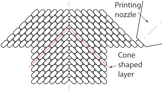
1.2. RotBot: 4-Axis Printer with Rotational Printing Head and Conic Slicing
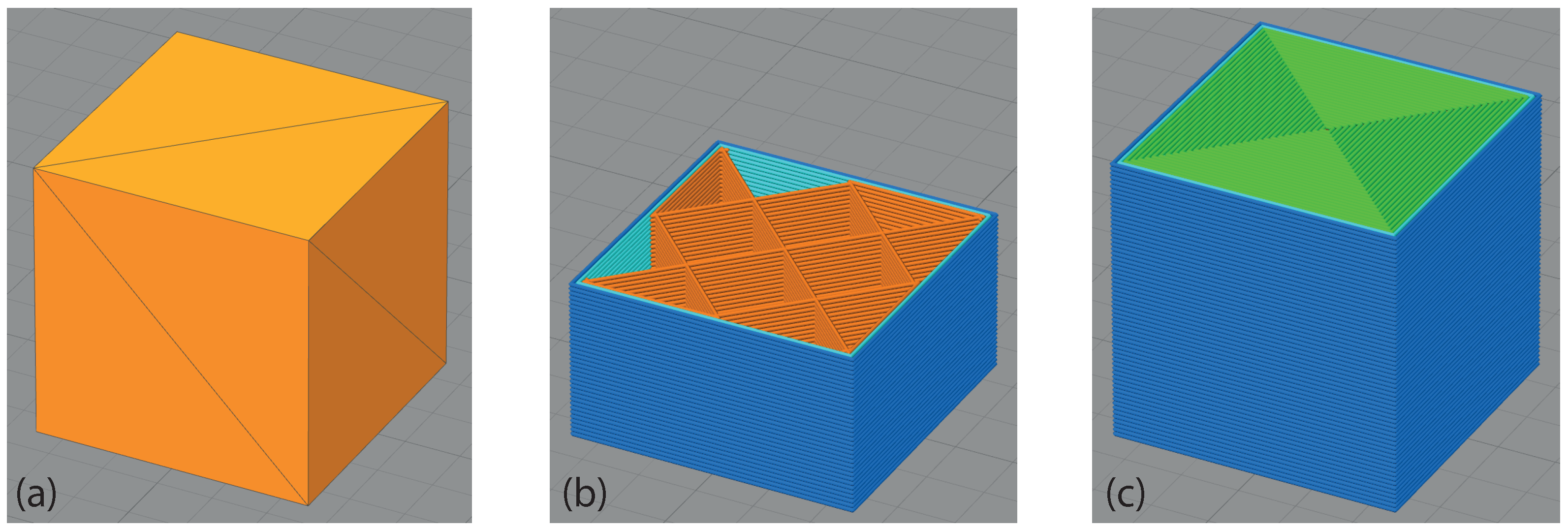
1.3. Conventional Slicing Process
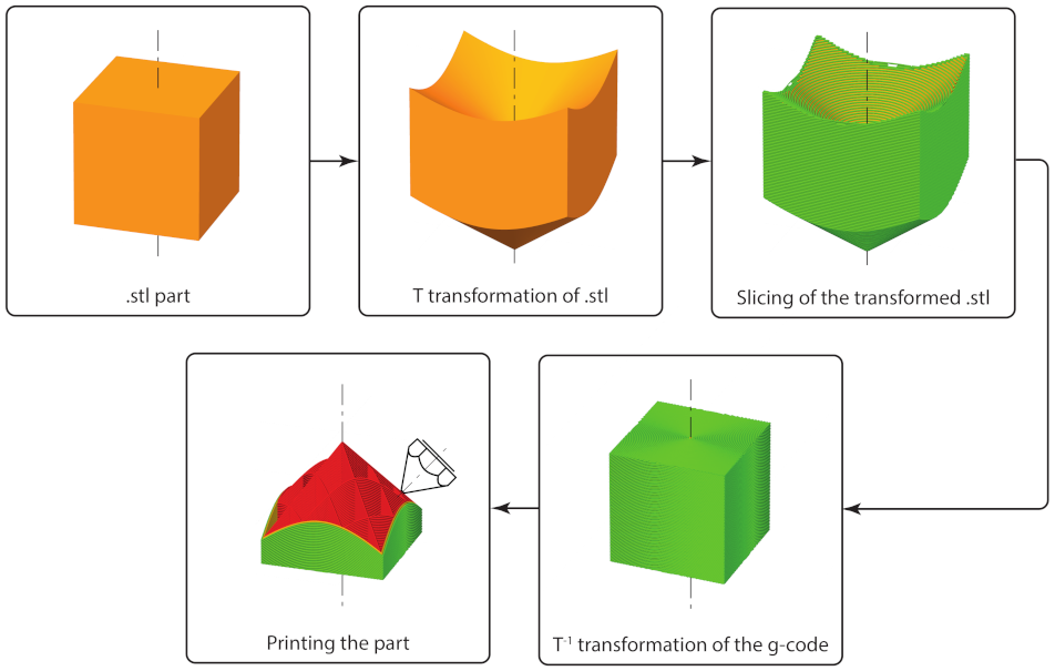
2. A Novel Slicing Strategy with Geometrical Pre- and Post-Transformation
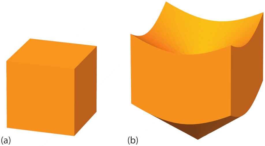
2.1. Geometrical Transformation for Cone Shaped Layers
2.2. Pre-Transformation of the STL File
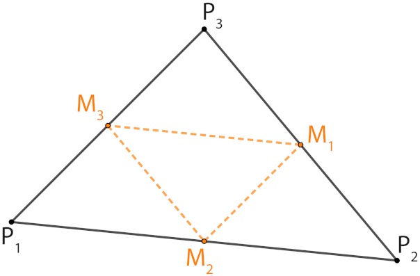
2.2.1. Refinement of Triangulation
2.2.2. Transformation of Triangles and Implementation of the Transformation
- 1.
- Read the STL file and store it as a MESH object.
- 2.
- Extract the array of triangles describing the object using the vector attribute.
- 3.
- Refine the triangulation by applying the refining step a given number of times. If there are N triangles and the refining step is done m times, the output is .
- 4.
- Apply the transformation T to the refined triangulation.
- 5.
- Store the transformed triangulation as a MESH object and save it in a new STL file.
2.3. Slicing in Conventional Slicer
- Layer height = mm
- Extrusion width = mm (diameter of the nozzle sets the maximum value)
- Number of perimeters = 2
- Outline Direction = Inside-Out
- Number of solid bottom layers = 0
- Number of solid top layers = 0
- Internal fill pattern = grid
2.4. Back-Transformation of G-Code
- 1.
- Splitting long elements into short segments
- 2.
- Transforming x, y and z
- 3.
- Adjusting the extrusion amount
- 4.
- Calculating the required angle of the rotational axis
- 5.
- Writing the new G-code
2.4.1. General Back-Transformation
- Coordinates of “old” point:
- “Old” coordinates back-transformed:
- Coordinates of “new” point:
- “New” coordinates back-transformed:
- z-coordinate of current layer:
2.4.2. Splitting Long Elements
2.4.3. Transforming x, y and z
2.4.4. Adjustment of Material Flow
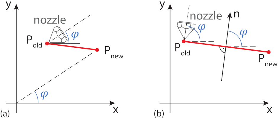
2.4.5. Calculation of the Nozzle Orientation
- Radial orientation: The nozzle is always oriented towards the origin of the coordinate system, no matter in what direction it moves.
- Tangential orientation: The nozzle is always perpendicular to the movement in the x- and y-plane.
2.4.6. Calculating the Rotational G-Code Values
- The units of the computed angle must be in degrees, so conversion may be required.
- The values of the angles are between . When crossing the x-axis for , this would lead the U-value to have “large, discontinuous” jumps.
2.4.7. Writing the New Code
2.5. Inward Cone: Slicing for Inward Overhangs
- an inward cone is used for the transformation and
- no material is extruded and
- the nozzle is moved in x- and/or y-direction
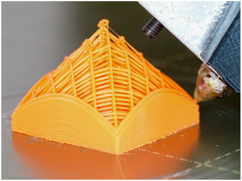
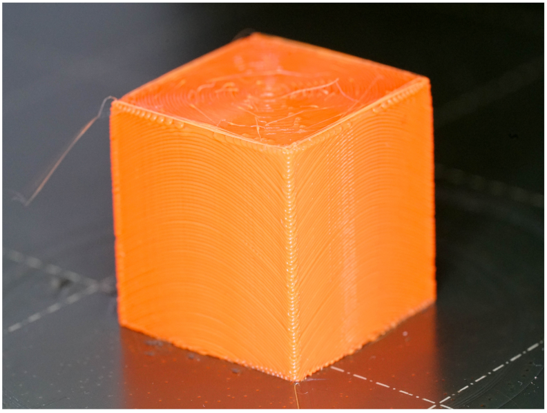
3. Results
4. Discussion
- The refinement of the triangles is done with a very simple approach. This leads to unoptimized STL files. The refinement should be done in a way, that only the bigger triangles are refined until all triangles are small enough to fulfill the requirements. To keep the number of triangles low, the already small triangles must not be affected.
- As stated in Section 3, the movement of the RotBot needs further improvement. The optimal speeds, accelerations and jerks of the different axes have to be optimized for the reduction of the printing time and constant printing quality.
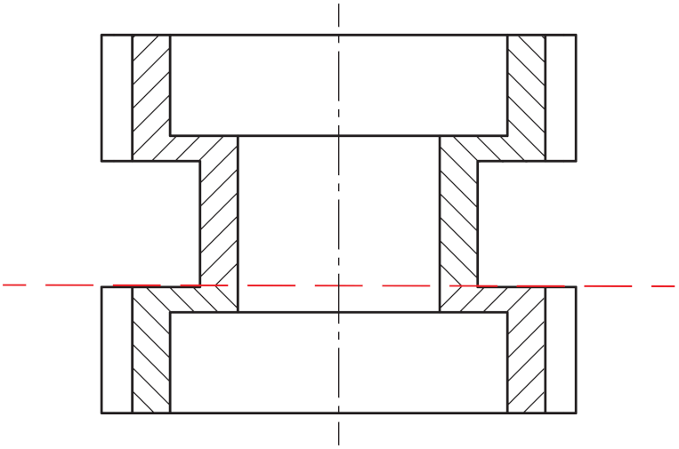
- As described in Section 1.2, more complicated geometries with a combination of overhangs to the inside and the outside direction must be separated and sliced independently. Up to now, this only has been done manually with very simple combinations as shown in Section 3. Further research and testing have to be done to manage a variety of different geometries, with the aim of an automated analysis and separation.
- Parts that can be sliced with only one outward transformation do not have any collision problem, since the printhead always is on the outside of the cone. However, parts with inward cones and parts with a combination of different cones do face collision problems. This has be investigated further and solutions have to be developed.
- The Python file for the back-transformation is optimized to work with G-codes from one defined slicer (Simplify3D). Other slicers could include commands into the G-code that are not handled correctly with the Python script. One example are the comment lines, which are used in the back-transformation script to differentiate between infill and perimeter. Therefore, a more generic Python script has to be written.
- It should also be considered to develop a completely new slicer software optimized for the conical layers. This would prevent the geometric transformation and reverse transformation and the slicing with a conventional slicer. Despite the enormous development effort, certain problems could be handled more directly in this way. For example, the refinement of the triangles or the splitting of the straight lines would be omitted. The quality problems could also be solved more easily since the slicer would be optimized for the conical layers.
5. Conclusions
- The study demonstrates that the novel slicing strategy with cone shaped layers works very well on the 4-axis printer.
- It is possible to print parts with 90° overhangs without the use of support material. The downward oriented surfaces have the same quality as the upward oriented surfaces.
- The accuracy of the printed part geometry and the surface roughness as well are not yet as good compared to a conventional 3D printer with orthogonal kinematics.
Author Contributions
Funding
Institutional Review Board Statement
Informed Consent Statement
Data Availability Statement
Conflicts of Interest
Abbreviations
| 3Dp | 3D printing |
| AM | Additive manufacturing |
| FDM | Fused Deposition Modeling |
| CNC | Computer Numeric Control |
| DED | Direct Energy Deposition (aka DMD) |
| ZHAW | Zurich University of Applied Sciences |
| STL | Standard Tessellation Language |
Appendix A
Appendix A.1
Appendix A.2
References
- Wong, K.V.; Hernandez, A. A Review of Additive Manufacturing. ISRN Mech. Eng. 2012, 2012, 1–10. [Google Scholar] [CrossRef] [Green Version]
- Thompson, M.K.; Moroni, G.; Vaneker, T.; Fadel, G.; Campbell, R.I.; Gibson, I.; Bernard, A.; Schulz, J.; Graf, P.; Ahuja, B.; et al. Design for Additive Manufacturing: Trends, opportunities, considerations, and constraints. CIRP Ann. 2016, 65, 737–760. [Google Scholar] [CrossRef] [Green Version]
- Rahim, T.N.A.T.; Abdullah, A.M.; Akil, H.M. Recent Developments in Fused Deposition Modeling-Based 3D Printing of Polymers and Their Composites. Polym. Rev. 2019, 59, 589–624. [Google Scholar] [CrossRef]
- Wulle, F.; Coupek, D.; Schäffner, F.; Verl, A.; Oberhofer, F.; Maier, T. Workpiece and Machine Design in Additive Manufacturing for Multi-Axis Fused Deposition Modeling. Procedia CIRP 2017, 60, 229–234. [Google Scholar] [CrossRef]
- Verbeeten, W.M.; Lorenzo-Bañuelos, M.; Arribas-Subiñas, P.J. Anisotropic rate-dependent mechanical behavior of Poly(Lactic Acid) processed by Material Extrusion Additive Manufacturing. Addit. Manuf. 2020, 31, 100968. [Google Scholar] [CrossRef]
- Jiang, J.; Xu, X.; Stringer, J. Support Structures for Additive Manufacturing: A Review. J. Manuf. Mater. Process. 2018, 2, 64. [Google Scholar] [CrossRef] [Green Version]
- Volpato, N.; Foggiatto, J.A.; Schwarz, D.C. The influence of support base on FDM accuracy in Z. Rapid Prototyp. J. 2014, 20, 182–191. [Google Scholar] [CrossRef]
- Coupek, D.; Friedrich, J.; Battran, D.; Riedel, O. Reduction of Support Structures and Building Time by Optimized Path Planning Algorithms in Multi-axis Additive Manufacturing. Procedia CIRP 2018, 67, 221–226. [Google Scholar] [CrossRef]
- Reeser, K.; Doiron, A.L. Three-Dimensional Printing on a Rotating Cylindrical Mandrel: A Review of Additive-Lathe 3D Printing Technology. 3D Print. Addit. Manuf. 2019, 6, 293–307. [Google Scholar] [CrossRef]
- Park, H.S.; Park, H.J.; Lee, J.; Kim, P.; Lee, J.S.; Lee, Y.J.; Seo, Y.B.; Kim, D.Y.; Ajiteru, O.; Lee, O.J.; et al. A 4-Axis Technique for Three-Dimensional Printing of an Artificial Trachea. Tissue Eng. Regen. Med. 2018, 15, 415–425. [Google Scholar] [CrossRef] [PubMed]
- Xu, K.; Chen, L.; Tang, K. Support-Free Layered Process Planning Toward 3+2-Axis Additive Manufacturing. IEEE Trans. Autom. Sci. Eng. 2019, 16, 838–850. [Google Scholar] [CrossRef]
- Murtezaoglu, Y.; Plakhotnik, D.; Stautner, M.; Vaneker, T.; van Houten, F.J. Geometry-Based Process Planning for Multi-Axis Support-Free Additive Manufacturing. Procedia CIRP 2018, 78, 73–78. [Google Scholar] [CrossRef]
- Lee, K.; Jee, H. Slicing algorithms for multi-axis 3-D metal printing of overhangs. J. Mech. Sci. Technol. 2015, 29, 5139–5144. [Google Scholar] [CrossRef]
- Sundaram, R.; Choi, J. A Slicing Procedure for 5-Axis LaserAided DMD Process. J. Manuf. Sci. Eng. 2004, 126, 632–636. [Google Scholar] [CrossRef]
- Wang, M.; Zhang, H.; Hu, Q.; Liu, D.; Lammer, H. Research and implementation of a non-supporting 3D printing method based on 5-axis dynamic slice algorithm. Robot. Comput.-Integr. Manuf. 2019, 57, 496–505. [Google Scholar] [CrossRef]
- Wu, C.; Dai, C.; Fang, G.; Liu, Y.J.; Wang, C.C. RoboFDM: A robotic system for support-free fabrication using FDM. In Proceedings of the 2017 IEEE International Conference on Robotics and Automation (ICRA), Singapore, 29 May–3 June 2017; IEEE: Piscataway, NJ, USA, 2017. [Google Scholar] [CrossRef]
- Ishak, I.B.; Fisher, J.; Larochelle, P. Robot Arm Platform for Additive Manufacturing Using Multi-Plane Toolpaths. In Proceedings of the Volume 5A: 40th Mechanisms and Robotics Conference; Charlotte, NC, USA, 21–24 August 2016, American Society of Mechanical Engineers: New York, NY, USA, 2016. [Google Scholar] [CrossRef] [Green Version]
- Zhao, G.; Ma, G.; Feng, J.; Xiao, W. Nonplanar slicing and path generation methods for robotic additive manufacturing. Int. J. Adv. Manuf. Technol. 2018, 96, 3149–3159. [Google Scholar] [CrossRef]
- Herrman, D.; Tolar, O. Weiterentwicklung der Gerätetechnik im FDM-Verfahren. Master’s Thesis, ZHAW, Winterthur, Switzerland, 2015. [Google Scholar]
- Wüthrich, M.; Elspass, W.J.; Bos, P.; Holdener, S. Novel 4-Axis 3D Printing Process to Print Overhangs Without Support Material. In Industrializing Additive Manufacturing; Meboldt, M., Klahn, C., Eds.; Springer International Publishing: Cham, Switzerland, 2021; pp. 130–145. [Google Scholar] [CrossRef]
- XYZdims.com. Available online: https://xyzdims.com/2021/03/03/3d-printing-90-overhangs-without-support-structure-with-non-planar-slicing-on-3-axis-printer/ (accessed on 19 July 2021).
- Gubser, M. FDM Printing of Overhangs without Support Material. Master’s Thesis, ZHAW, Winterthur, Switzerland, 2020. [Google Scholar]
- GitHub Software. Available online: https://github.com/RotBotSlicer/Transform (accessed on 18 August 2021).
- Numpy-STL Documentation. Available online: https://numpy-stl.readthedocs.io/en/latest/index.html (accessed on 19 July 2021).
- Turner, B.N.; Gold, S.A. A review of melt extrusion additive manufacturing processes: II. Materials, dimensional accuracy, and surface roughness. Rapid Prototyp. J. 2015, 21, 250–261. [Google Scholar] [CrossRef]
- Mohamed, O.A.; Masood, S.H.; Bhowmik, J.L. Optimization of fused deposition modeling process parameters: A review of current research and future prospects. Adv. Manuf. 2015, 3, 42–53. [Google Scholar] [CrossRef]
- Dey, A.; Yodo, N. A Systematic Survey of FDM Process Parameter Optimization and Their Influence on Part Characteristics. J. Manuf. Mater. Process. 2019, 3, 64. [Google Scholar] [CrossRef] [Green Version]
- Turek, P.; Budzik, G. Estimating the Accuracy of Mandible Anatomical Models Manufactured Using Material Extrusion Methods. Polymers 2021, 13, 2271. [Google Scholar] [CrossRef]
- Nancharaiah, T.; Raju, D.R.; Raju, V.R. An experimental investigation on surface quality and dimensional accuracy of FDM components. Int. J. Emerg. Technol. 2010, 1, 106–111. [Google Scholar]
- Polak, R.; Sedlacek, F.; Raz, K. Determination of FDM Printer Settings with Regard to Geometrical Accuracy. In DAAAM Proceedings; DAAAM International Vienna: Vienna, Austria, 2017; pp. 0561–0566. [Google Scholar] [CrossRef]




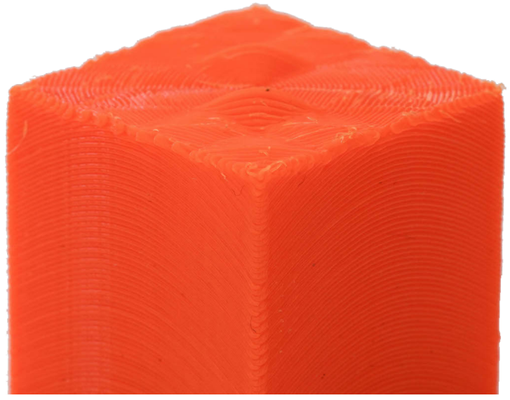
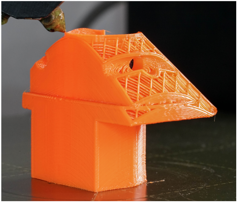
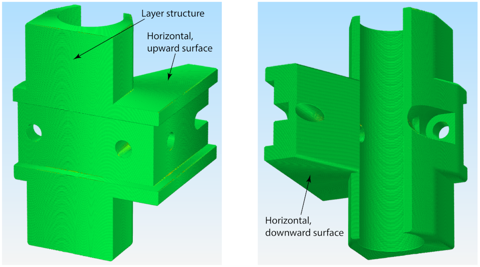
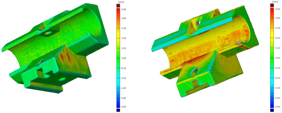


| Parameter | Prusa Mk3s | RotBot |
|---|---|---|
| Material | Prusament PLA (red) | Prusament PLA (orange) |
| Support | yes | no |
| Layer height | 0.3 mm | 0.3 mm |
| Infill | 20% | 20% |
| Printing speed (outer perimeter) | 2100 mm/s | 2520 mm/s |
| Printing time | 2 h 54 min | 3 h 58 min 1 |
| Surface | Ripple, min [μm] | Ripple, max [μm] | Sa [μm] |
|---|---|---|---|
| Vertical surface Prusa | −63.5 | +49.8 | 21.4 |
| Vertical surface RotBot | −64.8 | +47.6 | 20.7 |
| Upward surface Prusa | −23.8 | +22.1 | 8.3 |
| Upward surface RotBot | −99.0 | +94.8 | 33.1 |
| Downward surface Prusa | −129.9 | +72.1 | 37.8 |
| Downward surface RotBot | −98.6 | +85.9 | 29.9 |
Publisher’s Note: MDPI stays neutral with regard to jurisdictional claims in published maps and institutional affiliations. |
© 2021 by the authors. Licensee MDPI, Basel, Switzerland. This article is an open access article distributed under the terms and conditions of the Creative Commons Attribution (CC BY) license (https://creativecommons.org/licenses/by/4.0/).
Share and Cite
Wüthrich, M.; Gubser, M.; Elspass, W.J.; Jaeger, C. A Novel Slicing Strategy to Print Overhangs without Support Material. Appl. Sci. 2021, 11, 8760. https://doi.org/10.3390/app11188760
Wüthrich M, Gubser M, Elspass WJ, Jaeger C. A Novel Slicing Strategy to Print Overhangs without Support Material. Applied Sciences. 2021; 11(18):8760. https://doi.org/10.3390/app11188760
Chicago/Turabian StyleWüthrich, Michael, Maurus Gubser, Wilfried J. Elspass, and Christian Jaeger. 2021. "A Novel Slicing Strategy to Print Overhangs without Support Material" Applied Sciences 11, no. 18: 8760. https://doi.org/10.3390/app11188760
APA StyleWüthrich, M., Gubser, M., Elspass, W. J., & Jaeger, C. (2021). A Novel Slicing Strategy to Print Overhangs without Support Material. Applied Sciences, 11(18), 8760. https://doi.org/10.3390/app11188760


