Article

Towards an Efficient Chipless RFID System for Modern Applications in IoT Networks

by
Wazie M. Abdulkawi
*,
N. Nizam-Uddin
,
Abdel Fattah A. Sheta
,
Ibrahim Elshafiey
and
Abdullah M. Al-Shaalan
Electrical Engineering Department, King Saud University, Riyadh 11421, Saudi Arabia
*
Author to whom correspondence should be addressed.
Appl. Sci. 2021, 11(19), 8948; https://doi.org/10.3390/app11198948
Submission received: 24 August 2021 / Revised: 18 September 2021 / Accepted: 24 September 2021 / Published: 26 September 2021
(This article belongs to the Section Electrical, Electronics and Communications Engineering)

Abstract

:
In this article, we present the design and validation of an efficient chipless RFID system. A multi-resonator chipless tag is designed and tested for high bit coding capacity. A high gain, ultra-wideband step-shape rectangular patch (USRP) antenna is proposed to validate the specificity of the tag in terms of its operation. The devised antenna is evaluated for various performance parameters, which recommend its suitability for testing and validation of high-capacity tags that can be deployed in modern applications, particularly in the Internet of Things (IoT) networks. A measurement setup is established to achieve performance validation of the tag over a significant range of 40 cm. There is close agreement between the measured and simulated results, which suggests that the proposed antenna system can be adopted in a similar measurement setup to test and validate the performance of any chipless RFID tag operating in the same bandwidth meant for IoT networks.

1. Introduction

In recent years, the diffusion of various wireless technologies has shown natural binding affinity towards the Internet of Things (IoT). Under the framework of the IoT, the heterogeneous devices are networked together to share or transfer data wirelessly or in wired mode. With the addition of new sensors, devices, and subnetworks, the volume of the IoT is growing, and therefore an improvement in the pervasiveness of the IoT is in high demand. Low power or ideal self-powered devices having low cost with compact size can enhance the pervasiveness of IoT networks. Therefore, for such scenarios, chipless radio-frequency identification (RFID) tags and sensors are the most suitable devices to be widely deployed in IoT networks where tagging and sensing is required [1,2,3].
Chipless RFID tags and sensors are passive in nature, have miniaturized dimensions and low cost which can be deployed in a variety of applications such as defense and logistics, food processing, healthcare, agriculture and environment, retail industries, and banking, in addition to other applications that operate under the umbrella of the IoT framework [4,5,6,7,8].
Robust operation of IoT networks requires low latency, low powered miniaturized nodes and tags, appropriate communication range between nodes to prevent complex multi-hop transmissions, reduction of data packets collision and drops, and increased data throughput. These can be achieved by using pattern reconfigurability of the RFID readers, adopting multi-resonator RFID chipless tags, adopting more directive RFID antennas, and exploiting spatial reuse of the nodes [9].
With the bulk deployment of RFID tags in IoT networks, the integrity of the data generated must be maintained at every level. Therefore, data from the working nodes, RFID tags, sensors, and devices operating in IoT networks can be processed as Big Data, which incorporates methods and techniques related to data management, storage, and analysis [10,11]. To ensure the accuracy of data is preserved, the specificity of the RFID tags should be confirmed at deployment stages. Therefore, validation of devices such as chipless RFID tags working as a standalone system is inevitable.
Therefore, the presented research is an attempt to validate the specificity of a novel chipless RFID tag while operating as a standalone unit prior to its deployment in an IoT network. The proposed validation system is comprised of a chipless RFID tag that exhibits a high bit encoding capacity suitable to be adopted for IoT networks [12,13], and a high gain ultra-wideband antenna module [14,15,16]. The modeling and simulation of tag and antennas were performed in Computer Simulation Technology Microwave Studio while RT Duroid 5880 substrate (εr = 2.2, tan σ = 0.0009, and h = 0.79 mm) was used for fabrication.

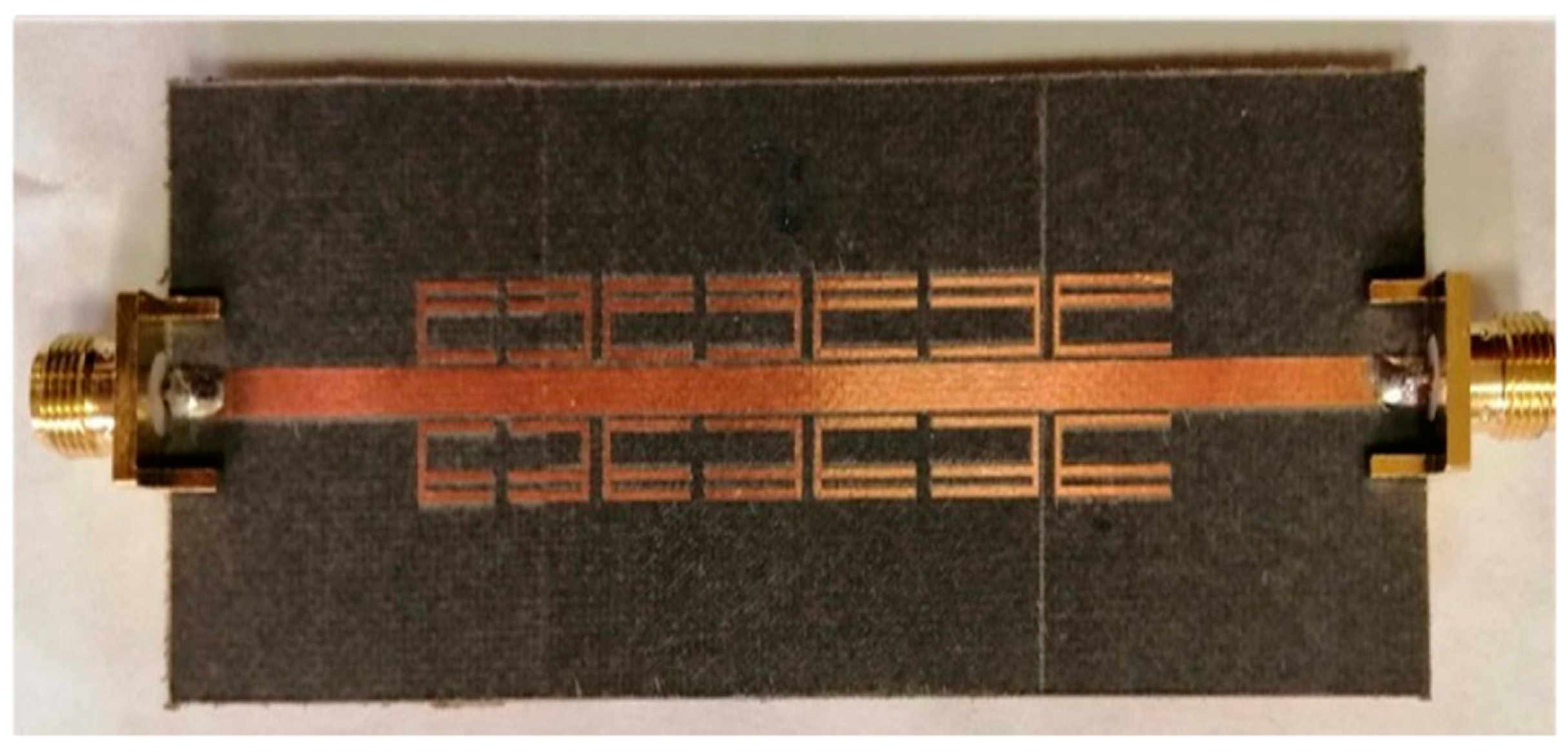
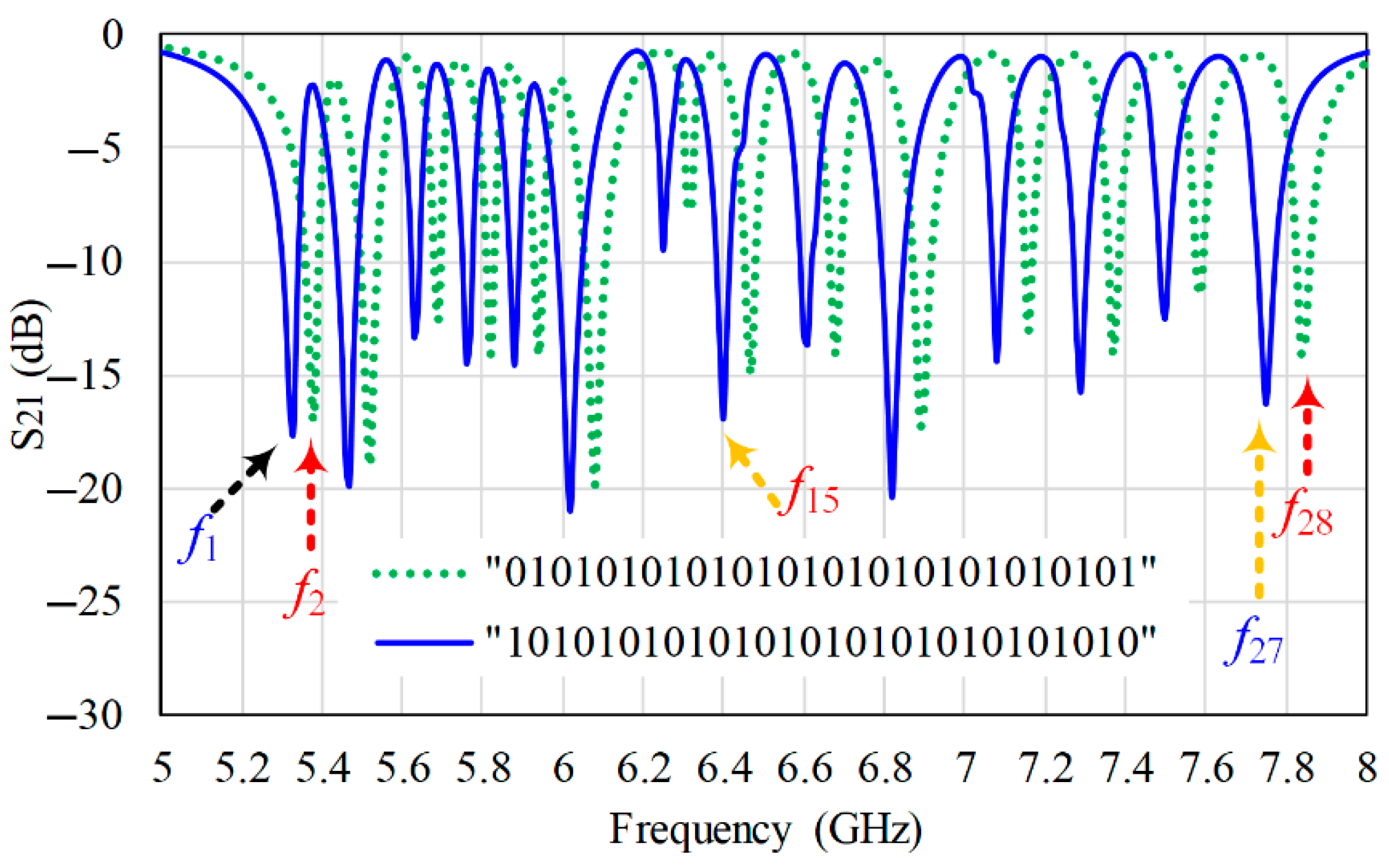
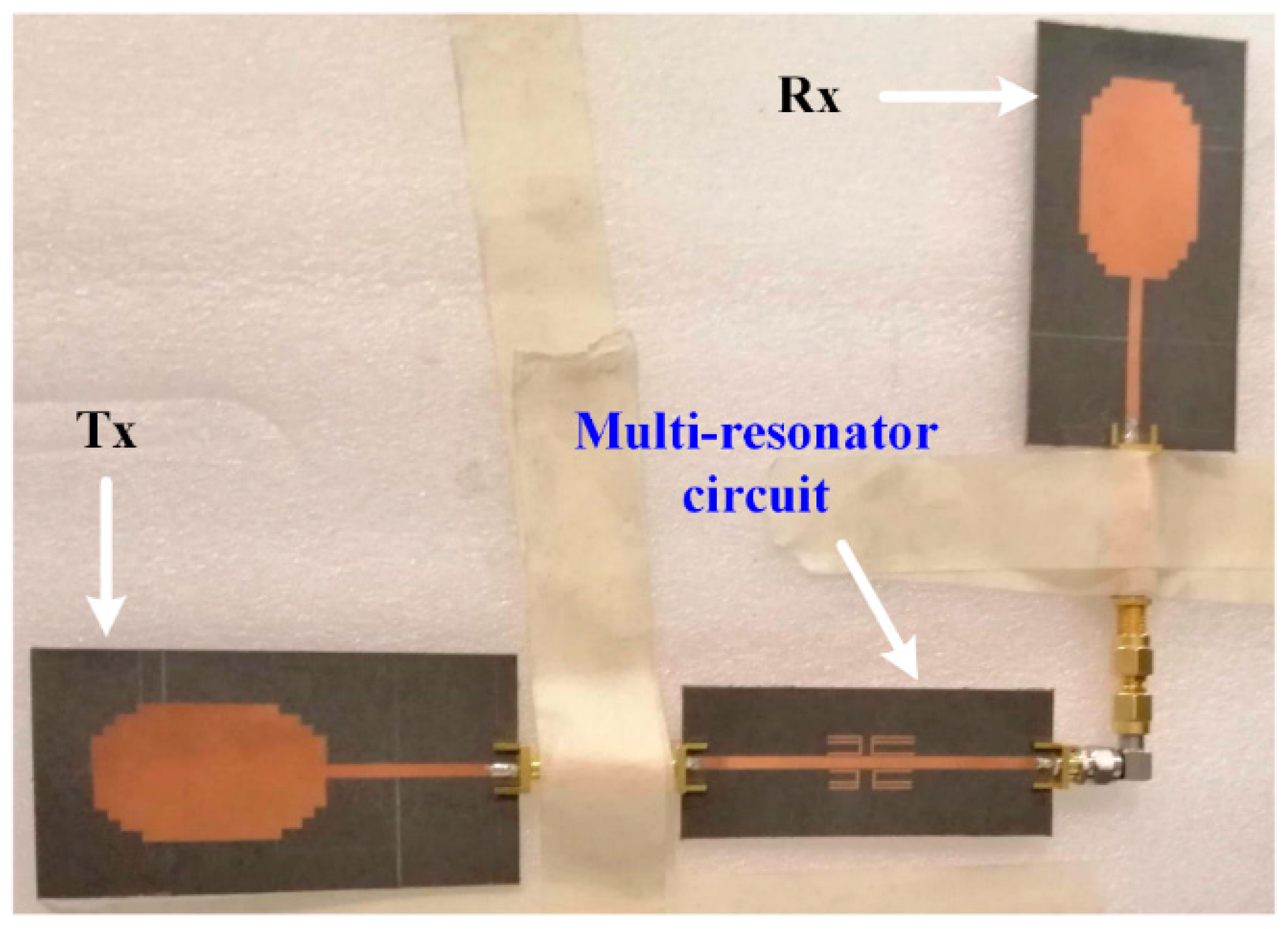
2. The RFID Tag Design

In this paper, we propose a tri-state coupled line microstrip resonator as a chipless RFID tag already presented in [17]. The proposed tag has 14 resonators as shown in Figure 1.
The information of each resonator can be encoded with two frequencies (f1 and f2); therefore, 28 possible frequencies can be configured, as depicted by its S-parameters in Figure 2.
It is worth mentioning that the frequency separation between f1 and f2 is 50 MHz, which can be varied by changing the widths of the arms, thus, making our design bandwidth flexible by enhancing the tag’s capacity without the need of broadening the required frequency bandwidth.
Furthermore, the proposed tag can be configured with other arm connection combinations, thereby yielding various bit combinations for storing information. Additionally, the bit encoding capability of the proposed tag in the high frequency spectrum suggests that its size can be further reduced and, consequently, the cost, if the tag is redesigned for high frequency applications such as object localization and robotics where accurate position resolution is required. This would also enable the tag to encode greater number of bits as the bandwidth increases, which is one the primary requirement of heterogeneous networks such as the IoT [18].

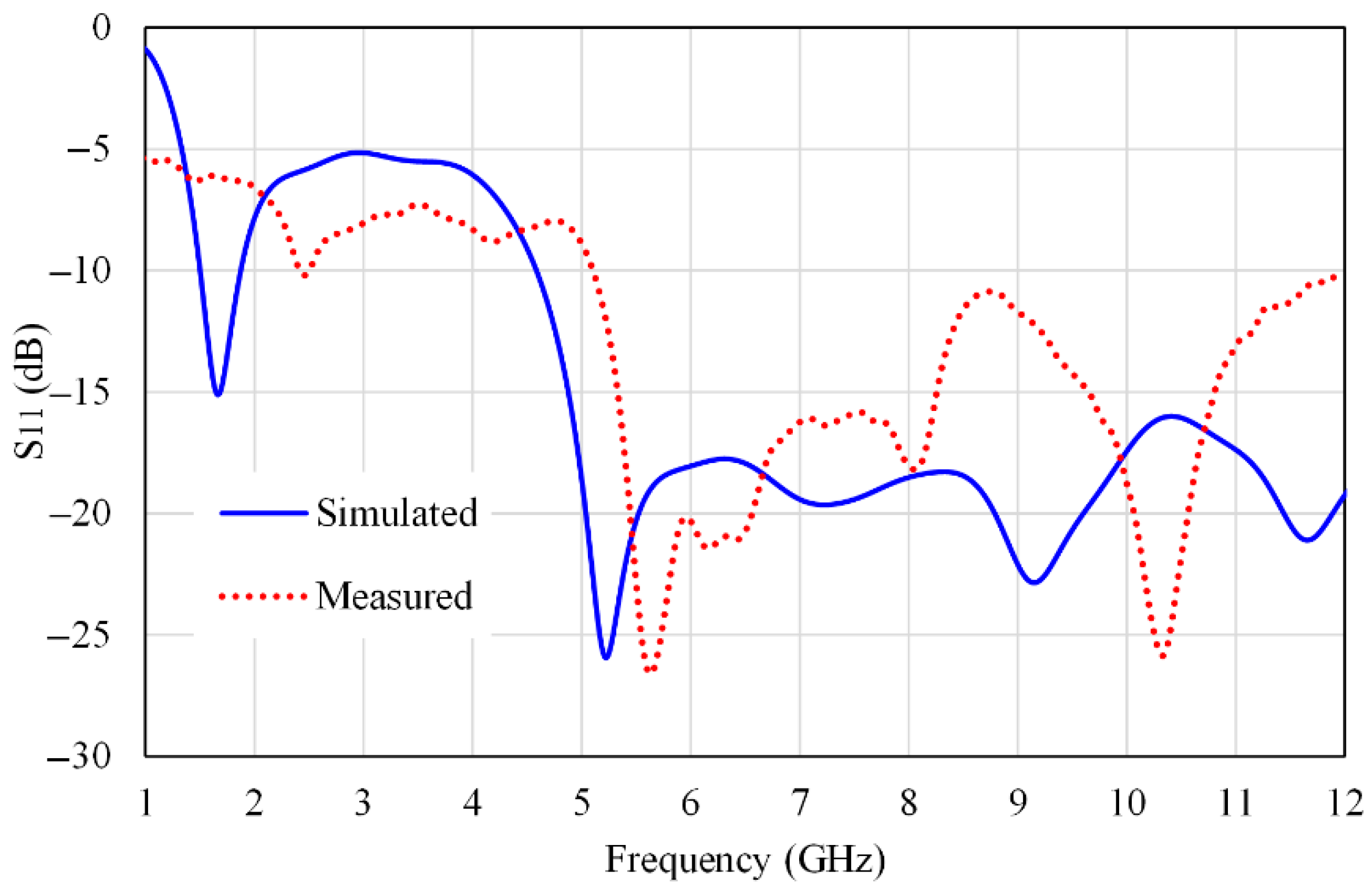
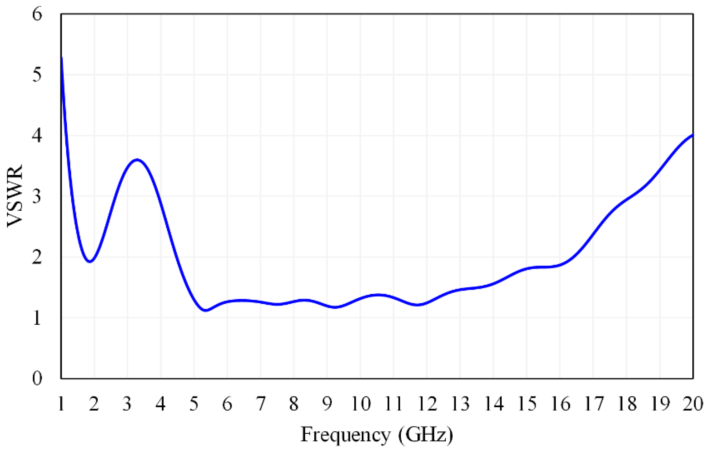
3. The RFID Antenna Design

Miniaturized ultra-wideband (UWB) antennas with high gain have been an area of interest for researchers in recent years, in particular, for RFID tags applications. Various techniques have been adopted to raise the bandwidth while maintaining a good gain-to-aperture ratio [19]. It includes meandered ground plane antenna design [20], monopole antenna with microstrip disc loading [21], dual-polarized microstrip patch antenna array [22], and UWB-printed circular monopole antenna [23]. It also includes patch antennas with gap-coupled feed [24] and an integrated band-pass filter [25]. However, the reported techniques come with various shortcomings, which include large size, low gain, reduced bandwidth, and copolarization effects [26,27]. Therefore, to overcome the discrepancies in the reported techniques, we are proposing an ultra-wideband step-shape rectangular patch (USRP) antenna.
The front side of the proposed antenna consists of a rectangular patch. The longer sides of the patch are cut in symmetric steps to increase the length for better bandwidth realization. A partial ground plane is adopted at the backside to maximize directivity and reduce back lobe radiation. The design parameters for the radiating patch, step cuts, feedline, and ground plane are listed in Table 1, while the fabricated antenna is shown in Figure 3.
The S-parameter response of the USRP antenna is shown in Figure 4, which depicts the fact that the antenna can also effectively operate in the bandwidth from 5 to 12 GHz making its bandwidth compatible with our proposed chipless tag, which operates from 5 to 8 GHz.
The seamless frequency operation of the USRP antenna can be examined from the VSWR graph of the antenna, as illustrated in Figure 5, which approaches an ideal value of one for a frequency range of 5–12 GHz.
The simulated gain characteristic of the USRP antenna is depicted in Figure 6, which illustrates the fact that the proposed antenna can achieve a maximum gain of 8 dB for a frequency range of 13.5–18 GHz. This makes the proposed antenna an ideal candidate to be used for an extended reading range.
The USRP antenna achieves radiation efficiency of more than 90% over a wideband of operating frequency, as shown in Figure 7.
Polarization sensitivity of an antenna is of paramount importance when it comes to designing an efficient RFID system. The co- and crosspolarization characteristics of the USRP antenna are shown in Figure 8. For an interference-free RFID system, there should be a high degree of copolarization between the antennas of different modules (tag and reader), such as communication between the reader’s transmitting antenna and the tag’s receiving antenna. Likewise, good crosspolarization should be exhibited between antennas of the same module, such as the tag’s transmitting and receiving antennas. This ensures clutter rejection and low dynamic noise from the hardware modules and environment whenever RFID is interrogated by the antenna’s signal.
The far field radiation pattern of the USRP antenna was investigated for various frequencies, including 2.5, 5, 7.5, and 10 GHz, as shown in Figure 9. From these figures, it is evident that the antenna exhibits an almost omnidirectional radiation pattern in the lower frequency bandwidth while maintaining a good value of gain.
The presented results justify the suitability of the USRP antenna for its deployment as a tag’s as well as reader’s antenna.

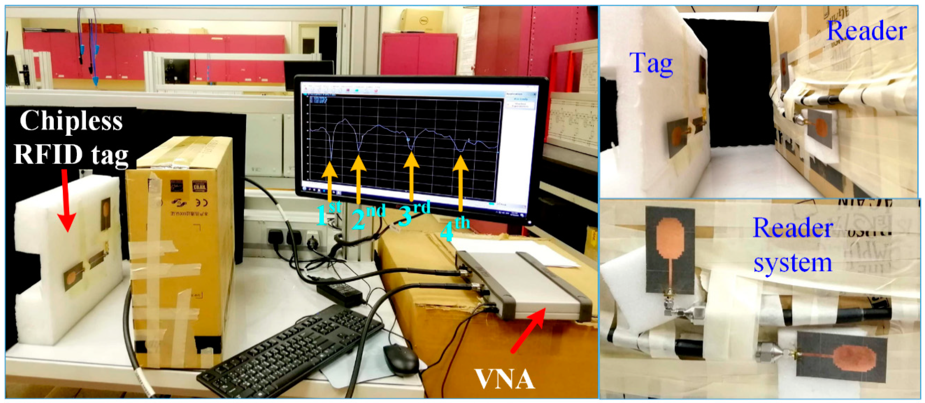
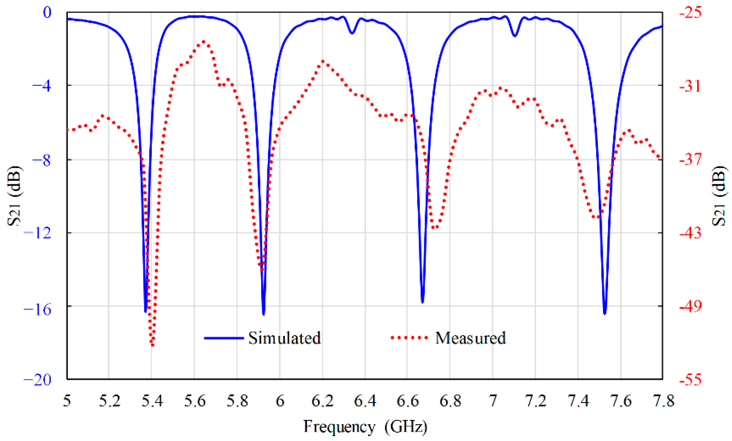
4. RFID System Validation

According to the information encoding mechanism, the chipless RFID tags are classified into two main categories: time-domain tags and frequency-domain tags. For robustness, frequency-domain tags are preferred over time-domain as the later suffers from propagation delays. A typical frequency-based chipless RFID tag is comprised of multiple resonators tuned to various frequencies distributed in a particular bandwidth. The antenna should be capable of generating an interrogating signal with a bandwidth that can cover all the resonant frequencies of the tag, thus, requiring a wideband antenna unit.
Validation of the RFID system also depends on the interaction of the interrogating signal with the tag and on the information retrieval mechanism. In a typical chipless RFID system, the tags can be deployed with readers in two modes; the retransmission mode and the radar cross-section (RCS) or backscattered mode [28,29]. In these modes, the reader interrogates the tag with electromagnetic (EM) waves to detect the encoded data of the tag. On the one hand, RCS tags are smaller in size, but the detection process is more complicated, requiring a number of measurements. Additionally, RCS RFID systems can sometimes suffer from crosstalk, and in some cases, they involve a single antenna for both transmission and reception. On the other hand, the retransmission tags are larger in size with a detection mechanism that is much simpler, which allows the tag to retransmit the electromagnetic (EM) signal to the reader that can detect the tag information according to variations in the frequency signature in the form magnitude or phase deviation. Additionally, the crosspolarization between the reader and tag antennas ensures minimum crosstalk while maintaining isolation between the transmitted and received signals [30]. The advantages associated with retransmitted chipless tags make them an ideal choice for a modern chipless RFID system. However, the efficiency of such RFID systems depends upon the design of high gain UWB antennas and multi-resonator chipless tags with high coding capacity [31].
In the presented research, a measurement test bench is implemented using a vector network analyzer (VNA-MS46122A) and two sets of USRP antennas. The first set of USRP antennas connects the input–output ports of the resonator tag to act as the tag’s transmitting and receiving antennas, respectively. This is shown in Figure 10. This arrangement ensures polarization mismatch between the transmitting and receiving antennas of the tag.
The other two antennas function as reader antennas that are orthogonally connected to the ports of the VNA at a distance of 40 cm from the tag. To ensure accuracy in the measurement, the transmitting antenna of the reader should be copolarized with the receiving antenna of the tag. Similarly, the receiver antenna of the reader and the transmitting antenna of the tag should be copolarized. A schematic of the main modules needed for the validation procedure is illustrated in Figure 11, while the actual measurement setup is shown in in Figure 12.
The S-parameter response (S21) is measured for the proposed RFID system. It is compared with the simulated response and shown in Figure 13. The results are both in good agreement, thus, validating the specificity of the RFID tag to be deployed in IoT networks. The slight variation occurs due to fabrication, feed line losses, and possible mutual coupling among the antenna elements.
Estimation of the received signal strength (RSS) is an important parameter to be quantified while designing an RFID system. Typically, a Friss free space transmission equation is used for this purpose, which can effectively quantify the loss in received power as a function of distance, frequency, and gain of the antennas. For the case of a retransmission based chipless RFID system, while considering line-of-sight power transfer, the Friss equation can be written as:
P R x   = P T x   G 2 T x   G 2 R x   λ 4   τ 2   ( 4 π d ) 4
where P R x   is the received power at the reader’s receiving (Rx) antenna and G R x is the gain; G T x represents the gain of the reader’s transmitting (Tx) antenna (the gains should both be equal because symmetrical antennas are used); λ is the free space wavelength; τ is the mismatch coefficient between the tag and its antenna, reflecting the insertion loss; d is the separation between the tag and reader modules.
One of the important parameters in Equation (1) is the tag-reader separation d, which defines the range of the system. Ideally, an efficient RFID system should be capable of decoding the tags’ information at a greater range, without an error and significant power drop. Table 2 summarizes the comparison between the range achieved for our proposed chipless RFID system and some reported works under arbitrary transmitting power conditions.
From the comparison in Table 2, it is evident that the proposed chipless RFID system can offer a greater detection range while operating in a high frequency range capable of producing high bit information density.

5. Conclusions

The design of an efficient RFID system and a chipless tag and antenna system have been presented. The chipless tag consists of multiple resonators, which reflect its high coding capacity. The devised antenna is a step-shape rectangular patch antenna capable of operating in UWB mode. Various performance parameters of the UWB were demonstrated, which confirmed its suitability to be utilized as a tag as well as reader antennas. A measurement setup was established, which validated the feasibility of the proposed RFID system for modern applications such as Internet of Things (IoT) applications.

Author Contributions

Conceptualization, W.M.A. and A.F.A.S.; software, W.M.A.; methodology, W.M.A., A.F.A.S., I.E., N.N.-U. and A.M.A.-S.; formal analysis, W.M.A., A.F.A.S., I.E., N.N.-U. and A.M.A.-S.; validation, W.M.A. and A.F.A.S.; investigation, A.F.A.S., I.E. and A.M.A.-S.; resources, A.F.A.S., I.E. and A.M.A.-S.; data curation, W.M.A.; writing (original draft preparation), W.M.A. and N.N.-U.; writing (review and editing), W.M.A., N.N.-U., A.F.A.S., I.E. and A.M.A.-S.; visualization, W.M.A. and N.N.-U.; supervision, A.F.A.S., I.E. and A.M.A.-S. All authors have read and agreed to the published version of the manuscript.

Funding

This research received no external funding.

Acknowledgments

The authors would like to acknowledge the Researchers Supporting Project number (RSP-2021/337), King Saud University, Riyadh, Saudi Arabia.

Conflicts of Interest

The authors declare no conflict of interest.

References

  1. Abdulkawi, W.M.; Sheta, A.-F.A. K-State Resonators for High-Coding-Capacity Chipless RFID Applications. IEEE Access 2019, 7, 185868–185878. [Google Scholar] [CrossRef]
  2. Mulloni, V.; Donelli, M. Chipless RFID Sensors for the Internet of Things: Challenges and Opportunities. Sensors 2020, 20, 2135. [Google Scholar] [CrossRef] [Green Version]
  3. Abdulkawi, W.M.; Issa, K.; Sheta, A.-F.A.; Alshebeili, S.A. A Novel Printable Tag of M-Shaped Strips for Chipless Radio-Frequency Identification in IoT Applications. Electronics 2020, 9, 2116. [Google Scholar] [CrossRef]
  4. Abdulkawi, W.M.; Sheta, A.F.A.; Issa, K.; Alshebeili, S.A. Compact Printable Inverted-M Shaped Chipless RFID Tag Using Dual-Polarized Excitation. Electronics 2019, 8, 580. [Google Scholar] [CrossRef] [Green Version]
  5. Ramzan, R.; Omar, M.; Siddiqui, O.; Ksiksi, T.; Bastaki, N. Internet of Trees (IoTr) Implemented by Highly Dispersive Electromagnetic Sensors. IEEE Sens. J. 2020, 21, 642–650. [Google Scholar] [CrossRef]
  6. Abdulkawi, W.M.; Sheta, A.-F.A. Chipless RFID Sensors Based on Multistate Coupled Line Resonators. Sens. Actuators A Phys. 2020, 309, 112025. [Google Scholar] [CrossRef]
  7. Sharma, V.; Hashmi, M. Advances in the Design Techniques and Applications of Chipless RFIDs. IEEE Access 2021, 9, 79264–79277. [Google Scholar] [CrossRef]
  8. Javed, N.; Azam, M.A.; Amin, Y. Chipless RFID Multi-sensor for Temperature Sensing and Crack Monitoring in an IoT Environment. IEEE Sens. Lett. 2021, 5, 1–4. [Google Scholar] [CrossRef]
  9. Trinh, L.H.; Le, T.N.; Staraj, R.; Ferrero, F.; Lizzi, L. A Pattern-Reconfigurable Slot Antenna for IoT Network Concentrators. Electronics 2017, 6, 105. [Google Scholar] [CrossRef] [Green Version]
  10. Marjani, M.; Nasaruddin, F.; Gani, A.; Karim, A.; Hashem, I.A.T.; Siddiqa, A.; Yaqoob, I. Big IoT data analytics: Architecture, opportunities, and open research challenges. IEEE Access 2017, 5, 5247–5261. [Google Scholar]
  11. Stergiou, C.; Psannis, K.E.; Gupta, B.B.; Ishibashi, Y. Security, privacy & efficiency of sustainable Cloud Computing for Big Data & IoT. Sustain. Comput. Inform. Syst. 2018, 19, 174–184. [Google Scholar] [CrossRef]
  12. Finkenzeller, K. RFID Handbook: Fundamentals and Applications in Contactless Smart Cards, Radio Frequency Identification and Near-Field Communication; John Wiley & Sons: London, UK, 2010. [Google Scholar]
  13. Preradovic, S.; Karmakar, N.C. Multiresonator-Based Chipless RFID: Barcode of the Future; Springer Science & Business Media: Berlin/Heidelberg, Germany, 2012. [Google Scholar]
  14. Rajasekhar, N.; Reddy, R.R.; Darimireddy, N. V-shaped slits and a slot loaded pentagonal boundary patch antennas for wideband applications. In Proceedings of the 2017 IEEE International Conference on Antenna Innovations & Modern Technologies for Ground, Aircraft and Satellite Applications (iAIM), Bangalore, India, 24–26 November 2017; pp. 1–5. [Google Scholar]
  15. Darimireddy, N.K.; Reddy, R.R.; Prasad, A.M. A Miniaturized Hexagonal-Triangular Fractal Antenna for Wide-Band Applications [Antenna Applications Corner]. IEEE Antennas Propag. Mag. 2018, 60, 104–110. [Google Scholar] [CrossRef]
  16. Sujatha, M.; Reddy, R.R.; Darimireddy, N.K.; Ramamohan, B. Multi Wideband Hexagonal-Spiral Microstrip Band-Pass Filter for Wireless Applications. In Proceedings of the 2018 IEEE Indian Conference on Antennas and Propogation (InCAP), New Delhi, India, 28–31 October 2018; pp. 1–4. [Google Scholar] [CrossRef]
  17. Abdulkawi, W.M.; Sheta, A.A. High coding capacity chipless radiofrequency identification tags. Microw. Opt. Technol. Lett. 2019, 62, 592–599. [Google Scholar] [CrossRef]
  18. Hussain, M.; Amin, Y.; Lee, K.-G. A Compact and Flexible UHF RFID Tag Antenna for Massive IoT Devices in 5G System. Sensors 2020, 20, 5713. [Google Scholar] [CrossRef] [PubMed]
  19. Ul, Z.; Ullah, Z.; Abedin, Z.U. Design of a Microstrip Patch Antenna with High Bandwidth and High Gain for UWB and Different Wireless Applications. Int. J. Adv. Comput. Sci. Appl. 2017, 8, 379–382. [Google Scholar] [CrossRef] [Green Version]
  20. Das, T.K.; Dwivedy, B.; Behera, S.K. Design of a meandered line microstrip antenna with a slotted ground plane for RFID applications. AEU-Int. J. Electron. Commun. 2020, 118, 153130. [Google Scholar] [CrossRef]
  21. Haraz, O.M.; Ashraf, M.; Alshebili, S.; Alshareef, M.R.; Behairy, H.M. UWB monopole antenna chipless RFID tags using 8-bit open circuit stub resonators. In Proceedings of the 2016 21st International Conference on Microwave, Radar and Wireless Communications (MIKON), Krakow, Poland, 9–11 May 2016; pp. 1–4. [Google Scholar]
  22. Babaeian, F.; Karmakar, N. A High Gain Dual Polarized Ultra-Wideband Array of Antenna for Chipless RFID Applications. IEEE Access 2018, 6, 73702–73712. [Google Scholar] [CrossRef]
  23. Ray, K.P.; Thakur, S.; Deshmukh, R.A. UWB printed sectoral monopole antenna with dual polarization. Microw. Opt. Technol. Lett. 2012, 54, 2066–2070. [Google Scholar] [CrossRef]
  24. Gupta, A.; Srivastava, D.K.; Saini, J.P.; Verma, R.K. Comparative analysis of microstrip-line-fed gap-coupled and direct-coupled microstrip patch antennas for wideband applications. J. Comput. Electron. 2019, 19, 457–468. [Google Scholar] [CrossRef]
  25. Daghari, M.; Sakli, H. Radiation performance enhancement of an ultra wide band antenna using metamaterial band-pass filter. Int. J. Electr. Comput. Eng. (IJECE) 2020, 10, 5861–5870. [Google Scholar] [CrossRef]
  26. Kirtania, S.; Younes, B.; Hossain, A.; Karacolak, T.; Sekhar, P. CPW-Fed Flexible Ultra-Wideband Antenna for IoT Applications. Micromachines 2021, 12, 453. [Google Scholar] [CrossRef]
  27. Aslam, B.; Kashif, M.; Amin, Y.; Tenhunen, H. Low-profile magnetically coupled dual resonance patch antenna for UHF RFID applications. AEU-Int. J. Electron. Commun. 2021, 133, 153672. [Google Scholar] [CrossRef]
  28. Babaeian, F.; Karmakar, N.C. Time and Frequency Domains Analysis of Chipless RFID Back-Scattered Tag Reflection. IoT 2020, 1, 7. [Google Scholar] [CrossRef]
  29. Herrojo, C.; Mata-Contreras, J.; Nunez, A.; Paredes, F.; Ramon, E.; Martin, F. Near-Field Chipless-RFID System with High Data Capacity for Security and Authentication Applications. IEEE Trans. Microw. Theory Tech. 2017, 65, 5298–5308. [Google Scholar] [CrossRef] [Green Version]
  30. Hossain, A.; Ibrahimy, M.; Motakabber, S.; Azam, S.; Islam, M. Multi-resonator application on size reduction for retransmission-based chipless RFID tag. Electron. Lett. 2021, 57, 26–29. [Google Scholar] [CrossRef]
  31. Preradovic, S.; Balbin, I.; Karmakar, N.; Swiegers, G.F. Multiresonator-Based Chipless RFID System for Low-Cost Item Tracking. IEEE Trans. Microw. Theory Tech. 2009, 57, 1411–1419. [Google Scholar] [CrossRef] [Green Version]
  32. Vena, A.; Perret, E.; Tedjini, S. A Depolarizing Chipless RFID Tag for Robust Detection and Its FCC Compliant UWB Reading System. IEEE Trans. Microw. Theory Tech. 2013, 61, 2982–2994. [Google Scholar] [CrossRef]
  33. Ma, Z.-H.; Yang, J.-H.; Chen, C.-C.; Yang, C.-F. A re-transmitted chipless tag using CSRR coupled structure. Microsyst. Technol. 2018, 24, 4373–4382. [Google Scholar] [CrossRef] [Green Version]
  34. Babaeian, F.; Karmakar, N. A UWB Antenna for Chipless RFID Tag Detection. In Proceedings of the 2020 International Conference on Electrical, Communication, and Computer Engineering (ICECCE), Istanbul, Turkey, 12–13 June 2020; pp. 1–6. [Google Scholar]
Figure 1. Porotype of the high coding capacity tag [17].
Applsci 11 08948 g001
Figure 2. The simulated S21 response of the tag [17].
Applsci 11 08948 g002
Figure 3. The proposed USRP antenna: (a) Fabricated view; (b) front and back view.
Applsci 11 08948 g003
Figure 4. S11 of the USRP antenna.
Applsci 11 08948 g004
Figure 5. VSWR of the USRP antenna.
Applsci 11 08948 g005
Figure 6. The gain frequency variation of URSP antenna.
Applsci 11 08948 g006
Figure 7. The total and radiation efficiencies as a function of frequency.
Applsci 11 08948 g007
Figure 8. Simulated results for antenna’s co- and crosspolarization characteristics.
Applsci 11 08948 g008
Figure 9. Simulated results of far field radiation pattern when the USRP antenna is operating at (A) 2.5 GHz; (B) 5 GHz; (C) 7.5 GHZ; (D) 10 GHz.
Applsci 11 08948 g009
Figure 10. The transponder: A pair of USRP antennas act as the tag’s transmitting and receiving antennas.
Applsci 11 08948 g010
Figure 11. The schematic of the main modules used for the RFID system validation.
Applsci 11 08948 g011
Figure 12. The actual measurement setup for the RFID system validation.
Applsci 11 08948 g012
Figure 13. Simulated and measured S21 for the proposed RFID system.
Applsci 11 08948 g013
Table 1. Physical parameters of the proposed antenna.
Patch DesignPartial Ground Plane
and Feed Line Design
Step-Cut Design
ParameterValue (mm)ParameterValue (mm)ParameterValue (mm)ParameterValue (mm)
Patch length (Lp)39.6Ground length (Lg)34.5l12.19w11.89
Patch width (Wp)25Ground width (Wg)25l22.11w21.99
Gap between the patch and ground plane0.52Feeder length (Lf)35l33.64w31.97
Feeder width (Wf)2.4l423.72w413.30
Table 2. Range comparison for chipless RFID systems.
ReferenceFrequency Bandwidth (GHz)Antenna TypeMax. Gain (dB)Range Achieved (cm)
[31]2 to 10 and 2 to 2.5Circular UWB monopole and LPDA1 and 5.55–40
[30]4.28 to 9fingertip-shaped
antenna (FSA)
-2
[32]2 to 32Commercial-10–20
[33]4.24 to 5.33UWB monopole1.8–2.530
[34]4.15 to 8UWB patch15.5 with two elements array 35
This work 5 to 12USRP840
Publisher’s Note: MDPI stays neutral with regard to jurisdictional claims in published maps and institutional affiliations.

