Article

Study on the Control of Torque Distribution of 4WD Corn Harvester Operation Drive

The College of Biological and Agricultural Engineering, Jilin University, 5988 Renmin Street, Changchun 130025, China
*
Author to whom correspondence should be addressed.
Appl. Sci. 2021, 11(19), 9152; https://doi.org/10.3390/app11199152
Submission received: 28 July 2021 / Revised: 25 September 2021 / Accepted: 28 September 2021 / Published: 1 October 2021
(This article belongs to the Section Agricultural Science and Technology)

Abstract

:
In response to the poor adaptability of existing harvesters to complex operating conditions in the field, this study took a three-row four-wheel-drive (4WD) corn harvester as the research object, designed a traveling transmission system layout, proposed a control strategy of driving torque distribution, simulated, and analyzed each of the four states of harvester drive wheels slippage. The results showed that under the driving wheels slipping condition, after applying torque control, the adjustment time was 43.3% shorter than that without control in the case of single wheel slipping, 11.1% shorter than that without control in the case of two wheels slipping on the same axle, 41.4% shorter than that without control in the case of two wheels slipping on different axles, and 36.6% shorter than that without control in the case of three driving wheels slipping. The application of drive torque distribution control could significantly improve the traction and passing ability of the corn harvesters during operation, as well as made the harvester travel more smoothly, thus improving the harvest quality. The drive torque distribution control can be applied not only to the three-row corn harvester, but also to other types of harvesters, and self-propelled agricultural machinery to enhance their adaptability, improving their operation quality. It has a significant reference value for the development of the driving system on walking agricultural machinery.

1. Introduction

Corn is one of the most widely planted food crops in the world [1,2,3]. Mechanized corn harvesting is an essential part of corn production. However, due to the complex landscapes such as plateaus, hills, and mountains, which account for more than half of the total global land area and nearly 70% of the national territory in China, the cultivated landscapes are variable and complex, making the existing self-propelled agricultural machinery such as harvesters not well adapted to the complex operating environment in the fields [4,5].
The New Holland CS series harvesters and the Clorox TUCAO series harvesters both used adaptive headers to increase their adaptability to the ground, ensure their harvest quality. Several scholars have designed self-balancing chassis to enhance the adaptability of the chassis to complex operating environments, increase operational safety, and improve operational quality [6,7]. Although these designs can reduce the impact of ground undulation on the operation quality to some extent, they cannot eliminate the impact of speed fluctuations caused by the slippage of the driving wheels of the travel machinery.
4WD (four-wheel-drive) can significantly reduce wheel slippage and improve the traction and driving stability of the vehicle [8,9]. 4WD torque distribution control could further improve the overall power performance of the travel machinery on this basis. 4WD torque control techniques have been studied extensively in inter-axle torque control, same-axle inter-wheel torque control, and integrated control. The research on inter-axle torque control mainly includes inter-axle differential characteristic analysis [10,11], torque distribution control research, and simulation analysis [12,13,14,15]. The research on inter-wheel torque control of the same axle mainly includes the design of differential structure [16,17,18], torque distribution control research, and simulation analysis [19,20]. The research on integrated control mainly focuses on the proposed control strategy and simulation analysis [21,22,23,24]. It has been proved that 4WD torque distribution control could effectively improve the traction, passing ability, and driving stability of the travel machinery. In this study, the 4WD torque distribution control technology was applied to the harvesters to solve the drive wheels slipping problem, reduce the speed fluctuation, enhance the passing ability and driving stability of the whole machine, and finally improve the operational performance of the harvesters.
In this study, a three-row wheeled 4WD corn harvester was used as the research object, a traveling transmission system layout was designed, the inter-axle and inter-wheel torque distribution devices were designed and optimized. The corn harvester had a large inertia, low speed, and high torque during operation, therefore electronically controlled disc brakes were used as a component to reduce the braking torque load by solidly connecting to the drive axles differential. Based on this travel drive system layout, a 4WD corn harvester drive torque distribution control strategy was proposed. The torque controller executed the control strategy controlling the corn harvester to complete a series of operations to eliminate drive wheel slip, adjust the whole machine operating posture, and enhance the field passing ability and driving stability of the harvester. The 4WD corn harvester drive torque distribution control was simulated by MATLAB/Simulink. The results showed that the applied torque distribution control of the 4WD corn harvester could significantly reduce the adjustment time when the drive wheels slipped, effectively reduce the speed fluctuation during the adjustment process, and immensely improve the field adaptability and operation quality of the corn harvester. This study provided a new method for the design and improvement of drive systems on harvesters and other walking agricultural machinery.

2. Design and Modeling

In this section, a torque distribution scheme for the three-row wheeled 4WD corn harvester was proposed. The inter-axle, inter-wheel torque distribution device, and brake mounting structure were optimized and designed. The mathematical models were established on this basis.

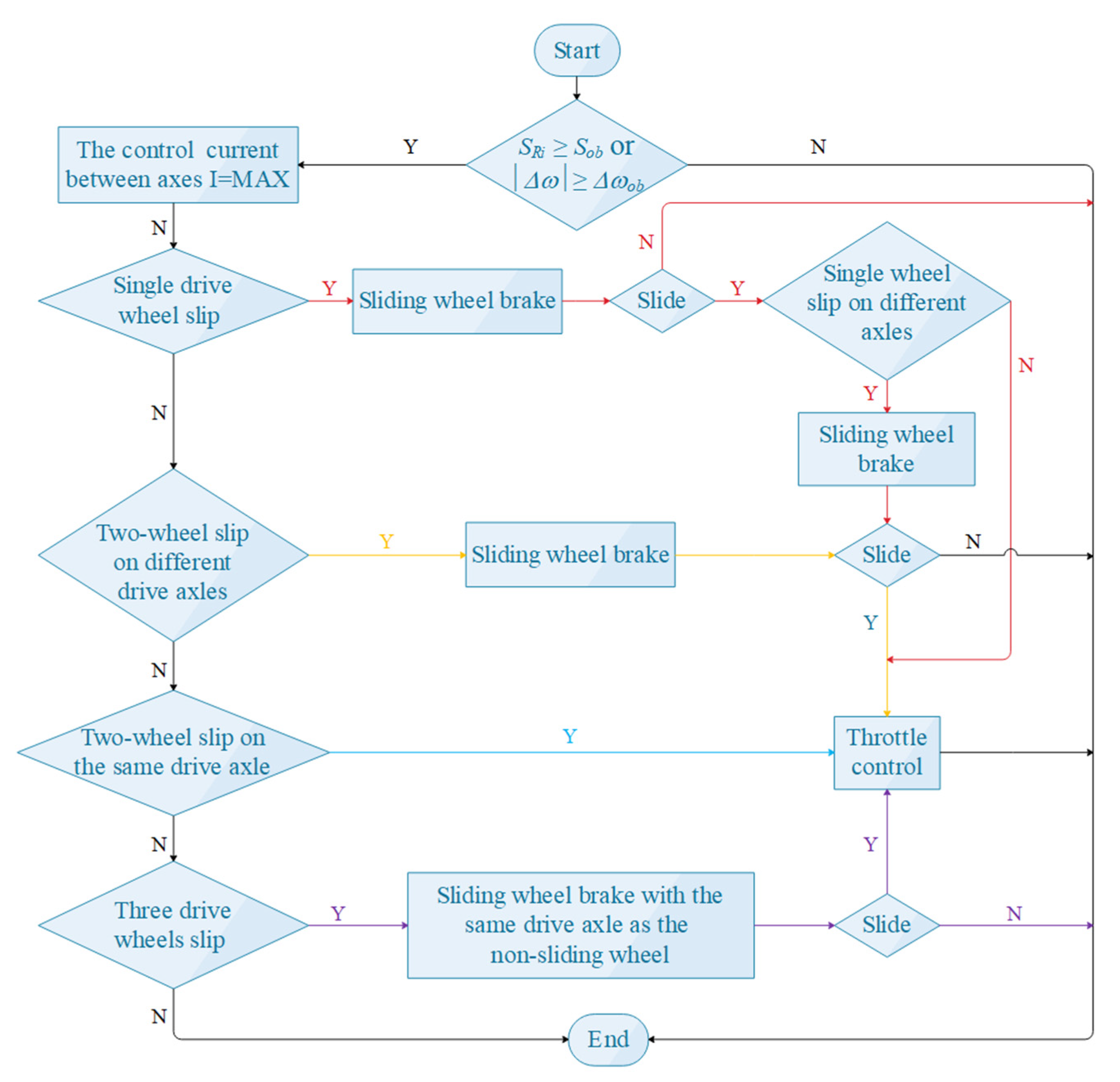
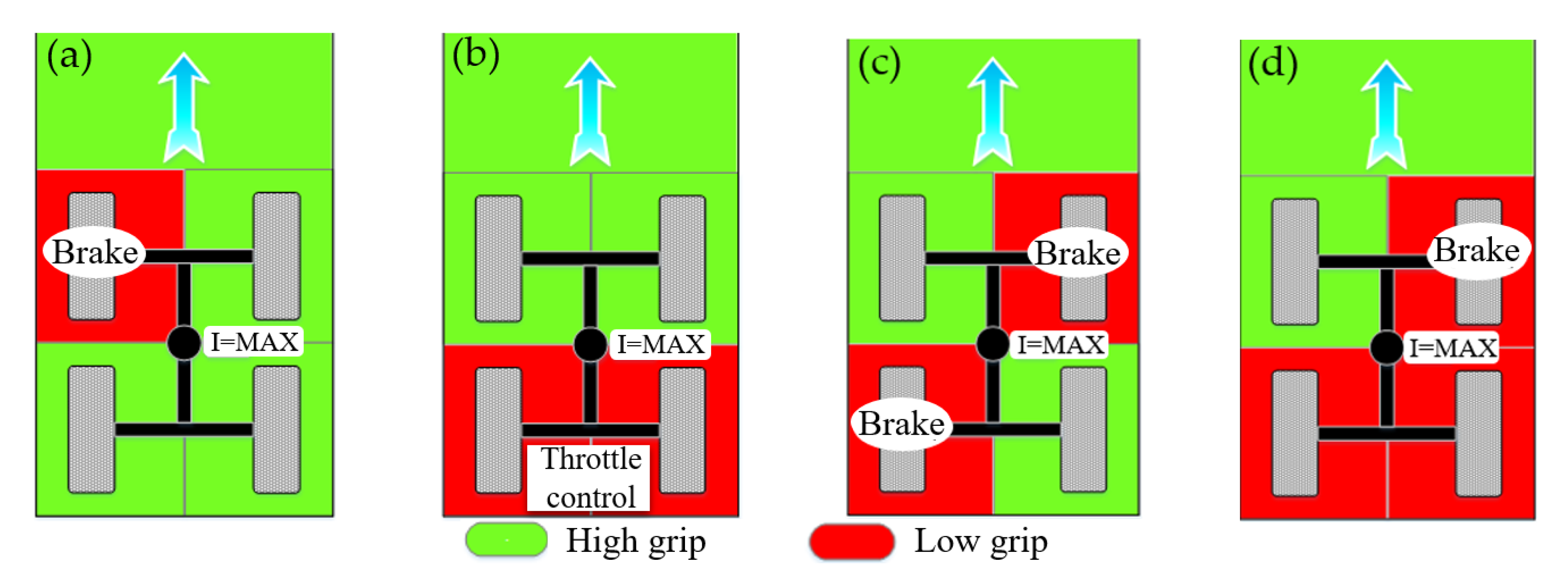
2.1. Torque Distribution Scheme and Control Principle

The torque distribution scheme of the corn harvester is shown in Figure 1. The power is output from the engine and transmitted to the automatic transmission through the V-belt, then the automatic transmission inputs the power to the inter-axle torque distribution device, finally the torque distribution device to actively distribute the torque between the front and rear axles. The torque on the rear-drive axle is freely distributed to the left and right drive wheels through the bevel gear differential, and the torque on the front drive axle is actively distributed to both drive wheels through the front drive axle inter-wheel torque distribution control device.
The drive torque control hardware mainly includes a torque controller, electronically controlled disc brakes, electronically controlled center differential, electronically controlled inter-axle differential, diesel throttle controller, and various sensors. Among them, the torque controller is the core. During operation, the torque controller managed the brakes, the electronically controlled center differential, and the diesel throttle controller to resolve torque distribution. When the drive wheel slip or a large speed difference between the front and rear drive axles, the torque controller will issue a corresponding control command after judging the status of the whole machine, control the brakes or inter-axle torque control device to prevent the drive wheels from slipping, and distribute the torque to other well-attached drive wheels, improve the traction of the whole machine. If the driving wheels still slip after control, it indicates that the engine output torque is too large, and the engine output torque needs to be adjusted by throttle control.

2.2. Establishment of the Mathematical Model

Based on the torque distribution scheme of the drive system, combining the specific structure of the inter-axle and inter-wheel torque distribution devices, the mathematical models of the whole machine, the inter-axle and inter-wheel torque distribution devices, the drive wheels, the engine, and the brakes were established.

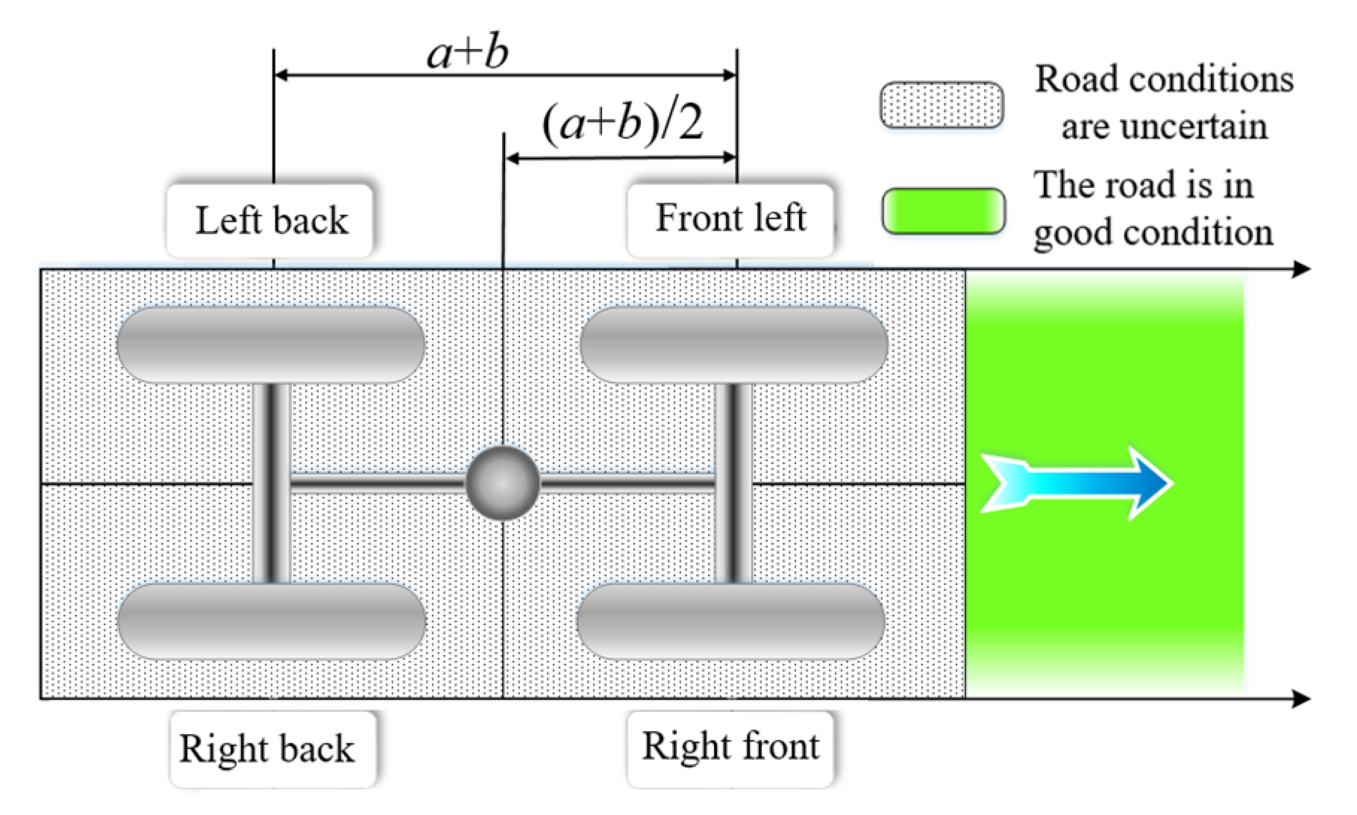
2.2.1. Mathematical Model of the Whole Machine

Some explorations have been done on the vehicle model building by Wong et al. [25]. With reference to the vehicle model establishment, the following mechanics model of the harvester was established.
The forces condition of the whole harvester in the absolute coordinate system is shown in Figure 2, where the x and y axes are shown, and the z-axis points from the vehicle mass center to the outside of the paper.
In the coordinate system, after analyzing the force situation of the harvester, the following equilibrium equations for the whole machine along x, y axes, and around the z-axis were established.
Transverse mechanical equilibrium equation:
m a y + V x γ ˙ = F y = ( F xwrl + F xwrr ) sin δ w + F ywfl + F ywfr + ( F ywrl + F ywrr ) cos δ w + f rl F zrl + f rr F zrr sin δ w 1 2 C Dy A y ρ V ry 2
longitudinal mechanical equilibrium equation:
m a x V y γ ˙ = F x = ( F xwrl + F xwrr ) cos δ w + F xwfl + F xwfr + ( F ywrl + F ywrr ) sin δ w f rl F zrl + f rr F zrr cos δ w f fl F zfl f fr F zfr 1 2 C Dx A x ρ V rx 2 mg sin α
equation of moment balance around z-axis:
J z γ ¨ = M z = [ F xwrr F xwrl + f rl F zrl f rr F zrr cos δ w + ( F ywrl + F ywrr ) sin δ w ] d r 2 + [ F xwrr + F xwrl f rl F zrl f rr F zrr sin δ w ( F ywrl + F ywrr ) cos δ w ] b + F xwfr F xwfl + f fl F zfl f fr F zfr d f 2 + F ywfl + F ywfr a + 1 2 C Dy A y ρ V ry 2 l x
the harvester travels slowly during operation, the effect of wind speed on the harvester is small, therefore, neglected in the subsequent analysis [26]. The meaning of each parameter in the formula is shown in Table 1.

2.2.2. Mathematical Model of Driving Wheels

Drive wheel tires are the power interface between the harvesters and the ground, their structures, and mechanical characteristics are crucial to the travel and operational performance of the whole harvester [27]. To study the various cases of slippage of harvester tires on the same plane, the Gim tire model was selected in this study [28,29,30], and the following mechanical characteristics model of tires were established.
In the tire rolling state:
F xw = C s s s l n 2 + μ x F z ( 1 3 l n 2 + 2 l n 3 )
F yw = C a s a l n 2 + μ y F z ( 1 3 l n 2 + 2 l n 3 )
In the tire slipping state:
F xw = μ x F z
F yw = μ y F z
the lateral camber angle of the tire was neglected in the modeling process.
At the same time, the mathematical model of each of the four driving wheels was established as follows:
ω ˙ fl = ω ˙ of + [ ( F xwfr r w + f fr F zfr r w + M bfr ) ( f fl F zfl r w + r w F xwfl + M bfl ) ] / ( 2 j wf )
ω ˙ fr = ω ˙ of + [ ( f fl F zfl r w + r w F xwfl + M bfl ) ( F xwfr r w + f fr F zfr r w + M bfr ) ] / ( 2 j wf )
ω ˙ rl = ω ˙ or + [ ( F xwrr r wr + f rr F zrr r wr + M brr ) ( f rl F zrl r wr + r wr F xwrl + M brl ) ] / ( 2 j wf )
ω ˙ rr = ω ˙ or + [ ( f rl F zrl r wr + r wr F xwrl + M brl ) ( F xwrr r wr + f rr F zrr r wr + M brr ) ] / ( 2 j wf )
the specific meanings of each parameter in Equations (8)–(11) are shown in Table 1. Meanwhile, the sub-reducer is integrated into the main reducer of the corresponding axle, and at this time, the angular velocity of the driving wheel and the corresponding half-axle are the same.

2.2.3. Mathematical Model of Inter-Axle and Inter-Wheel Torque Distribution Device

The active torque distribution control between the front axle drive wheels used an active torque control differential, consisting of an electronically controlled clutch, a master clutch, a common symmetrical bevel gear differential, and a triplex compound gear, which could achieve torque distribution while taking the sensitive and fast control into account [31]. The active friction plate of the clutch was fixed to one half-axle of the differential, and the two sets of driven friction plates were connected to the housing of the symmetrical bevel gear differential through a composite gear. When the clutch on the left side was combined, as shown in Figure 3a, the output torque of the right half-axle of the rear axle differential decrease, and the output torque of the left half-axle increase; the situation was reversed when the clutch on the right side was combined [32].
Torque distribution characteristics of the front axle torque differential when the left clutch is combined:
T fl = T fi 2 + Z 1 Z 6 2 Z 3 Z 4 T cl T fr = T fi 2 1 Z 1 Z 6 2 Z 3 Z 4 T cl
similarly, when the right clutch is combined:
T fl = T fi 2 Z 1 Z 5 2 Z 2 Z 4 T cr T fr = T fi 2 + 1 Z 1 Z 5 2 Z 2 Z 4 T cr
where T cl and T cr are the control torques between the left and right wheels of the front axle, respectively; T fi is the input torque; T fr is the torque output to the right front wheel; T fl is the torque output to the left front wheel; Z1, Z2, Z3, Z4, Z5, Z6 are the number of teeth of the corresponding gears, respectively.
The inter-axle torque distribution control is implemented by an electronically controlled central planetary gear differential, the structure of which is shown in Figure 3b. In the figure, Ti is the input torque; Tr is the torque output to the rear axle; Tf is the torque output to the front axle. The torque output from the transmission is first applied to the gears fixed to the planetary carrier, and the input torque is later distributed to the front drive axle connected to the ring gear as well as the rear-drive axle connected to the sun gear through a single row planetary gears. The torque distribution between the two axles is controlled by a control clutch between the planetary carrier and the rear output axle.
The control torque of the control clutch is
T c = π μ z μ c ε o r z r k npq 2 4 r t I 2
where εo is the vacuum permeability; p is the number of active friction plate working surfaces of the main clutch of the inter-axle differential; n is the number of driven friction plate working surfaces of the main clutch of the inter-axle differential; rt is the armature pole radius; q is the coil turns; rk is the effective working radius of the control clutch of the inter-axle differential; rz is the effective radius of the main clutch of the inter-axle differential; μz and μc are the friction coefficient of the main clutch friction plate and the control clutch friction plate, respectively. The input is the clutch control current I, and the output is the generated limited-slip torque [33].
The active differential can actively distribute the drive torque to the drive wheels on both sides of the axle according to the harvester driving conditions and the road condition, thus improv the driving stability of the harvester [34,35]. Friction was discarded in modeling the central differential with the drive wheels [33].
Mathematical model of the front and rear axles of the central differential:
ω ˙ of = { ω ˙ od + [ ( F xwrr r wr + f rr F zrr r wr + r wr F xwrl + f rl F zrl r w + M brl + M brr ) z x / i or z t + kT c ( F xwfr r w + f fr F zfr r w + r w F xwfl + f fl F zfl r w + r w F xwfl + M bfl + M bfr ) / i of ] / ( j f + j r ) } i of
ω ˙ or = { ω ˙ od + [ F xwfr r w + f fr F zfr r w + r w F xwfl + f fl F zfl r w + r w F xwfl + M bfl + M bfr ) z t / i of z x kT c ( F xwrr r wr + f rr F zrr r wr + r wr F xwrl + f rl F zrl r w + M brl + M brr ) / i or ] / ( j f + j r ) } i or
the meaning of each parameter in Equations (15) and (16) is shown in Table 1.

2.2.4. The Mathematical Model of Engine

The torque controller controls the amount of engine output torque by adjusting the throttle opening. The throttle position is controlled using a proportional-integral (PI) control algorithm, the input deviation is e, and the output throttle opening increments is ∆kd.
e = v r λ ( ω 1 + ω 2 + ω 3 + ω 4 ) R / 4
e is the increment of e, corresponds to the increment of throttle opening as
k d = e k p + e k i
in Equations (17) and (18), kp and ki are the proportional and integral factors of the harvester throttle controller, respectively; λ is the throttle controller adjustment parameter; vr is the reference vehicle speed; rw is the driving wheel radius; ω1, ω2, ω3, and ω4 are the left front, right front, left rear, and right rear drive wheel angular velocities, respectively.
The engine speed variation is a dynamic process during the harvester start-up, and when the harvester is operating in the field, the engine is also in non-stationary operation all the time. Therefore, the engine was simplified to an inertial system, with the following dynamic mathematical model [36,37,38,39]:
T e = T es e ST e 1 1 + ST e 2
where Te is the output torque of the engine; Tes is the steady torque of the engine; S is a torque characteristic coefficient of the diesel engine; kd is the throttle opening of the engine; Te1 and Te2 are the system time constant and the hysteresis constant, respectively.

2.2.5. The Mathematical Model of Brakes

The harvester has a high degree of inertia, to ensure good braking control performance, reduce the braking torque load of the brake, miniaturize the brake structure, combine the speed-torque with other mechanical relationships, this study designed a harvester brake with the mounting structure shown in Figure 4, which was not mounted directly on the drive wheels but was fastened as a component to the differential part of the harvester drive axle.
Each of the four drive wheels adopted independent floating electronically controlled disc brakes, which makes the drive torque active distribution control between the drive wheels more precise and also makes the harvester have a better safety performance. The principle of active inter-wheel torque distribution control is shown in Figure 4. If one of the two drive wheels on the same drive axle takes a certain degree of braking, the torque input to the drive axle will be transferred from the braking wheel to the other drive wheel through the differential, thus realizing the inter-wheel torque distribution control.
In this study, a logic gate algorithm was used to design the brake control system with three control states: pressurization, pressure-holding, and decompression, and the corresponding output control signals were digital in and out (DIO) = 1, 2, 3; the input signals were the angular acceleration ω ˙ , and the relative slip rate SRi of the corresponding drive wheels.
The corresponding slip rate of each tire is
S R 1 = ω 1 ω 2 ω 1 S R 2 = ω 2 ω 1 ω 2 S R 3 = ω 3 ω 4 ω 3 S R 4 = ω 4 ω 3 ω 4
where SR1, SR2, SR3, and SR4 in SRi i = 1 , 2 , 3 , 4 are the left front, right front, left rear, and right rear drive wheel slip rates, respectively; Sob is the target control setting slip rate. The specific control strategy is shown in Table 2.
On this basis, the torque model and pressure model of the brakes were established. The pressure model inputs the control signal in and outputs the pressure signal P. The output pressure signal P is used as the input signal of the torque model to make it output the braking torque Mb.
Mathematical model of the brakes:
P = P o + P max 1 e tK t , in = 0 P o , in = 1 P o e tK t , in = 3
M b = i b K b P
the solenoid brake command in Equations (21) and (22) is entered as 0 for brake pressurization, 1 for brake pressure-holding, and 3 for brake decompression.
Where P o is the initial brake pressure; t is the duration; Kt is the brake braking time coefficient; ib is the ratio of the brake transmission mechanism; Kb is the braking coefficient.

3. Simulation and Result Analysis

Combining the above design and modeling, this study proposed a three-row wheeled 4WD corn harvester torque active distribution control strategy, set the initial simulation conditions, simulated the established harvester models through the MATLAB/Simulink.

3.1. Torque Control Strategy and Simulation Initial Conditions

A combination of engine control, inter-axle torque distribution, and drive wheel braking was used to improve the traction performance and field passing ability of the harvester, and to enhance the adaptability to the complex operating environments of the harvester. According to the dynamics of the differential and the hierarchical module design, the control strategy of the harvester operation drive torque distribution was obtained, as shown in Figure 5.
Where, △ω was the front and rear axle speed difference and △ωob was the target setting value.
During the operation, there were four different working conditions as shown in Figure 6, single-wheel slip, two-wheel slip with the same axle, and different axle, single-wheel non-slip. When the slip rate of a drive wheel was greater than the target value, or the absolute value of the speed difference between the front and rear drive axles was greater than the target value, the inter-axle torque control started, the inter-axle control current was taken to the maximum value, the front and rear axle speed was adjusted to the same, and then further slip judgment and control was performed, as shown in Figure 5.
The torque control strategy of the three-row wheeled 4WD corn harvester experimental model was simulated by the MATLAB/Simulink, and the simulation results were analyzed. The main simulation parameters are shown in Table 3.
The initial position of the simulation is shown in Figure 7, with good road conditions, an initial speed of 3 m/s, a slope angle of 10°, an accelerator pedal of 100%, and the wheel steering angle of 0°. Figure 6 shows the schematic diagram of the initial control based on the inter-axle torque control.

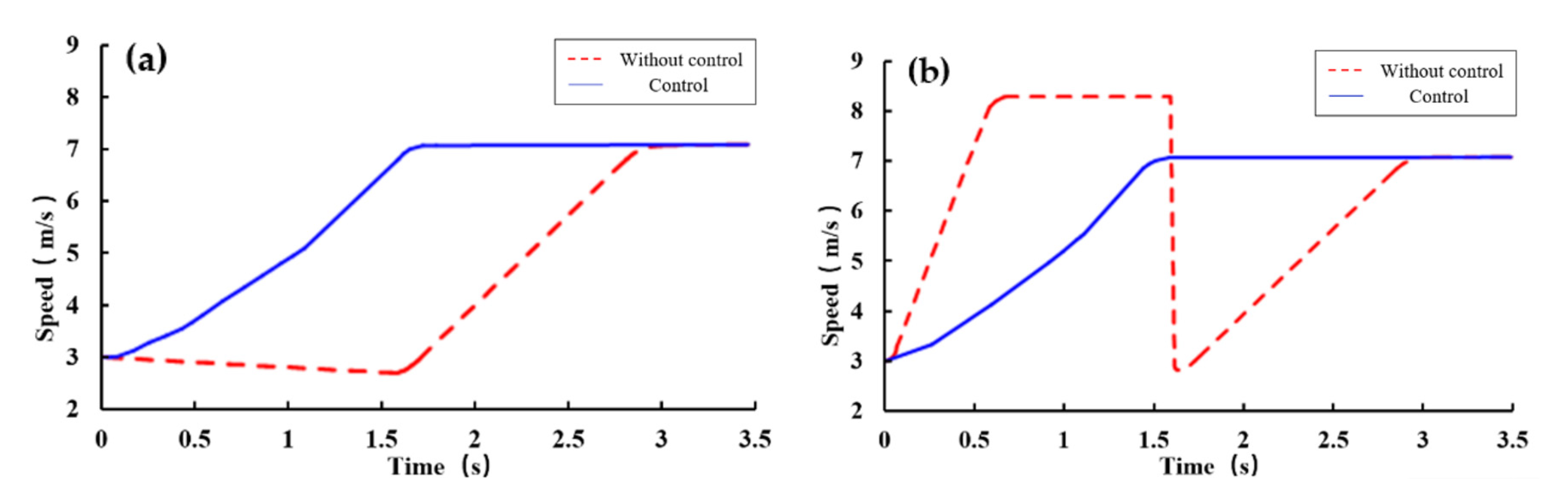
3.2. Front Left Wheel Slip Simulation

The initial state of the simulation was the left front wheel slipping, after the inter-axle torque control. The adjustment control process was to brake the slipping wheel to a certain extent based on the inter-axle differential clutch combination, so that part of the driving torque was transferred to the well-attached driving wheels, and if it slipped again, further torque control was carried out, and if necessary, engine output torque control was carried out in conjunction with engine throttle control. Finally, the traction force of the whole machine was improved. The simulation results are shown in Figure 8a,b. The dashed lines were the variation law of the harvester speed and the speed of the slipping wheel with time when no control was applied, and the solid lines were the corresponding speed variation law after the control was applied.
The simulation results showed, when no control was applied to the harvester, within 1.7 s, the speed of the slipping wheel first rose sharply to the maximum value due to slippage and then fell sharply to below 3 km/h due to the increase in attachment, during which the speed of the harvester showed a decreasing trend due to the slip of the wheel. After 1.7 s, the speed of the harvester increased with the speed of the slipping wheel and finally reached the uniform speed at the same time. The harvester speed and the slip wheel speed fluctuated greatly during the whole process, and the speed of the slip wheel was overshoot, the maximum overshoot was 17.86%; after the torque control was applied, as shown in the solid line in Figure 8, the speed of the harvester and the speed of the slipping wheel rose steadily during the whole adjustment process, and the adjustment time to reach the uniform speed was 43.3% shorter than that without control.
In summary, active torque control distribution could quickly eliminate single drive wheel slippage, and improve the passing ability and driving stability of the harvester during operation.

3.3. Simulation of Double Rear Wheels Slip with the Same Axle

The initial state of the simulation was the slipping of the rear axle double drive wheels, after the inter-axle torque control. Since both wheels of the rear axle were in the slipping state, the inter-wheel torque control failed to operate, and the adjustment process was controlled by the engine output to eliminate the slipping. The simulation results are shown in Figure 9a,b.
From the simulation results, when no control was applied to the harvester, within 0.6 s, the average speed of the slipping wheels first rose sharply to the maximum value due to slippage and then fell sharply to below 3 km/h due to the increase in attachment, during which the speed of the harvester showed a decreasing trend due to wheels slippage. After 0.6 s, the speed of the harvester rose with the speed of the slip wheels and finally reached the uniform speed at the same time. The harvester speed and the average speed of the slip wheels fluctuated greatly during the whole process, and the average speed of the slip wheels was overshoot, the maximum overshoot was 3.57%; after the control was applied, as shown in the solid line in Figure 9, the harvester speed and the average speed of the slip wheels were in a steady rise during the whole adjustment process, and the adjustment time to reach the uniform speed was 11.1% shorter than that when the control was not applied.
In summary, active torque control distribution could effectively eliminate double rear wheels slip with the same axle, and improve the passing ability as well as driving stability of the harvester during operation.

3.4. Simulation of Two-Wheel Slip with Different Axles

The initial state of the simulation was the front right and rear left drive wheels slipping after inter-axle torque control, and the adjustment process was to perform slipping wheels braking based on the initial inter-axle torque control so that some drive torque on the slipping wheels was transferred to the well-attached drive wheels, and if they slipped again, further engine output torque control was applied. Finally adjusted to no drive wheels slipping. The simulation results are shown in Figure 10a,b.
From the simulation results, when no control was applied to the harvester, within 1.7 s, the average speed of the slip wheels first rose sharply to the maximum value due to slippage and then fell sharply to below 3 km/h due to the increase in attachment, during which the speed of the harvester showed a decreasing trend due to wheels slippage. After 1.7 s, the harvester speed increased with the average speed of the slip wheels and finally reached the uniform speed at the same time. The harvester speed and the speed of the slip wheel fluctuated greatly during the whole process, and the speed of the slip wheel was overshoot, the maximum overshoot was 17.14%; after the control was applied, as shown in the solid line in Figure 10, the speed of the harvester and the average speed of the slip wheels increased steadily during the whole adjustment process, and the adjustment time to reach the uniform speed was 41.4% shorter than that when the control was not applied.
In summary, active torque control distribution could effectively eliminate two-wheel slip with different axles, and improve the passing ability as well as the driving stability of the harvester during operation.

3.5. Simulation When Only the Front Left Wheel Does Not Slip

The initial state of the simulation was a state where only the front left wheel did not slip after inter-axle torque control. The adjustment control process was to apply a certain degree of braking to the corresponding slipping wheels based on the inter-axle differential clutch combination so that the part of the driving torque was transferred to the left front drive wheel; if it slipped again, further torque control was carried out, and if necessary, engine output torque control was implemented to finally improve the traction. The traction force of the whole machine was finally improved. The simulation results are shown in Figure 11a,b.
The simulation results showed, when no control was applied to the harvester, within 1.6 s, the average speed of the slip wheels first rose sharply to the maximum value due to slippage and then fell sharply to below 3 km/h due to the increase in attachment, and the speed of the harvester showed a decreasing trend due to wheels slippage during the process. After 1.6 s, the speed increased with the average speed of the slip wheels and finally reached the uniform speed at the same time. The harvester speed and the speed of the slip wheel fluctuated greatly during the whole process, and the speed of the slip wheel was overshoot, the maximum overshoot was 17.14%; after the control was applied, as shown in the solid line in Figure 11, the speed of the harvester and the average speed of the slip wheels increased steadily during the whole adjustment process, and the adjustment time to reach the uniform speed was 36.6% shorter than that when the control was not applied. From the speed change curve, it could be qualitatively analyzed that in the process of adjusting the harvester drive wheel slippage, the tractive force of both the whole harvester and the well-attached drive wheels increased after the torque control was applied compared with that without the torque control, which was able to make the adjustment time shorter.
In summary, active torque control distribution could effectively eliminate three-wheel slip, and improve the passing ability as well as driving stability of the harvester during operation.

3.6. Qualitative Analysis of the Traction Force

The changes of traction force during the whole adjustment process could be analyzed qualitatively by the changes in the average speed of harvester and slipped wheels. During the adjustment process, there are two variables, driving torque and road adhesion, which affect the changes of traction force of harvester and driving wheels. A sharp decline in ground adhesion causes the harvester driving wheels to slip, at this time, if the harvester does not apply torque control, the torque is not redistributed, and the traction force of harvester slipping driving wheels decreases while the traction force of non-slip driving wheels remains unchanged, resulting in the traction force of the harvester as a whole not being supplemented after the decline. If the torque control is applied when the driving wheel is slipping, the torque of each driving wheel of the harvester is redistributed, and the torque on the slipping wheels is redistributed to other driving wheels with good grip after braking, and as the grip of other driving wheels is not reduced, the driving torque increases, increasing tractive force, thus increasing the tractive force of the whole harvester and reducing the time of harvester slipping adjustment. Finally, in the next stage, we will quantitatively analyze the traction force of the whole harvester and the drive wheels.

4. Conclusions

The results showed that with both inter-axle and inter-wheel torque control in operation, the adjustment time for harvester drive wheel slippage was reduced by more than 35% compared to without control. When the inter-wheel torque distribution control failed to work in the case of double drive wheels slipping on the same axle, the adjustment time was still shortened by 11.1% than without control. Before the applied torque control, the speed fluctuation was obvious, the average speed of the slipping wheels was overshoot, and the maximum overshoot was 17.86% in the case of the front left wheel slip. After applied the torque control, the overshoot phenomenon was eliminated and the speed fluctuation was significantly reduced.
The drive torque distribution control could improve the traction performance and field passing ability of the three-row 4WD corn harvester, enhance its adaptability to the complex field environment, effectively reduce the speed fluctuation during operation, and greatly improve the harvesting quality of the harvester. In addition, real-time torque control could distribute the torque from the slipping wheels to other well-attached driving wheels, which effectively avoids power waste and plays an energy-saving role. This study also provides a new methodology for the design and improvement of drive systems on harvesters and other walking agricultural machinery.

Author Contributions

Conceptualization, D.Z. and B.W.; validation, P.H., Y.X. and X.L.; writing—original draft, P.H.; writing—review and editing, D.Z. and B.W.; supervision, J.Z., H.Y. and Q.Z. All authors have read and agreed to the published version of the manuscript.

Funding

This research was supported by the Key Projects of Science and Technology Development Plan of Jilin Province, China (Grant no. 20170204015NY); Provincial School Joint Construction Project of Jilin Province, China (Grant no. SXGJXX2017-6); the National Key Research and Development Program of China (Grant no. 2016YFD070190103).

Conflicts of Interest

The authors declare no conflict of interest.

References

  1. Xu, J.; Meng, J.H.; Quackenbush, L.J. Use of remote sensing to predict the optimal harvest date of corn. Field Crop Res. 2019, 236, 1–13. [Google Scholar] [CrossRef]
  2. Ferraretto, L.F.; Shaver, R.D.; Luck, B.D. Silage review: Recent advances and future technologies for whole-plant and fractionated corn silage harvesting. J. Dairy Sci. 2018, 101, 3937–3951. [Google Scholar] [CrossRef] [PubMed]
  3. Shao, Y.E.; Dai, J.T. Integrated Feature Selection of ARIMA with computational intelligence approaches for food crop price prediction. Complexity 2018, 2018, 1–17. [Google Scholar] [CrossRef]
  4. Wang, Y.J.; Yang, F.Z.; Pan, G.T.; Liu, H.Y.; Liu, Z.J.; Zhang, J.Q. Design and testing of a small remote-control hillside tractor. Trans. ASABE 2014, 57, 363–370. [Google Scholar]
  5. Sun, C.R.; Nakashima, H.; Shimizu, H.; Miyasaka, J.; Ohdoi, K. Physics engine application to overturning dynamics analysis on banks and uniform slopes for an agricultural tractor with a rollover protective structure. Biosyst. Eng. 2019, 185, 150–190. [Google Scholar] [CrossRef] [Green Version]
  6. Qi, W.C.; Zhang, J.H. Dual closed-loop fuzzy PID control method for tractor body leveling in hilly areas. J. Agric. Mach. 2019, 50, 17–23, 34. [Google Scholar]
  7. Geng, A.J.; Zhang, M.; Zhang, J.; Zhang, Z.L.; Gao, A.; Zheng, J.L. Design and test of automatic height control system for corn harvester cutting platform. J. Agric. Mach. 2020, 51, 118–125. [Google Scholar]
  8. Naunhei-mer, H.; Ryborz, J.; Bertsche, B.; Song, J.J.; Gong, S.Y. Automotive Transmission Principle Selection Design and Application; Machinery Industry Press: Beijing, China, 2013. [Google Scholar]
  9. Janulevicius, A.; Juostas, A.; Pupinis, G. Estimation of tractor wheel slippage with different tire pressures for 4WD and 2WD wheel drive systems. In Proceedings of the Engineering for Rural Development-International Scientific Conference, Jelgava, Latvia, 22–24 May 2019; pp. 88–93. [Google Scholar]
  10. Piyabongkarn, D.; Lew, J.Y.; Rajamani, R.; Grogg, J.A. Active driveline torque-management systems. IEEE Control Syst. 2010, 30, 86–102. [Google Scholar]
  11. Chen, L.Q.; Tan, Y.D.; Wu, R.; Miao, W.; Hu, F. Torque distribution control strategy of electronically controlled four-wheel drive axle based on genetic algorithm. Soc. Agric. Mach. 2017, 48, 361–367. [Google Scholar]
  12. Ge, A.L.; Guo, L.S.; Zhang, T. Study of electronically controlled optimal torque distribution system for 4WD. J. Agric. Mach. 2002, 6, 16–19. [Google Scholar]
  13. Wong, A.; Kasinathan, D.; Khajepour, A.; Chen, S. Integrated torque vectoring and power management framework for electric vehicles. Control Eng. Pract. 2016, 48, 22–36. [Google Scholar] [CrossRef]
  14. De, N.L.; Sorniottia, G.P.; Gruber, P. Wheel torque distribution criteria for electric vehicles with torque-vectoring differentials. IEEE Trans. Veh. Technol. 2014, 63, 1593–1602. [Google Scholar]
  15. Hyeongcheol, L. Four-wheel drive control system using a clutch lesscentre limited slip differential. Proc. Inst. Mech. Eng. Part D J. Automob. Eng. 2006, 220, 665–681. [Google Scholar]
  16. Wang, J.H.; Wang, Y.C.; Fu, T.J. Study on the effect of torque type limited slip differential on the handling stability of rear wheel drive vehicles. Automot. Eng. 2006, 28, 460–464. [Google Scholar]
  17. Shi, J.P.; Sun, Q.H. Theoretical Study on Determination of Torque Distribution Ratio of Splitter. Automot. Eng. 2007, 29, 889–892. [Google Scholar]
  18. Wheals, J.C.; Deane, M.; Drury, S.; Griffith, G.; Harman, P.; Parkinson, R.; Shepherd, S.; Turner, A. Design and Simulation of a Torque Vectoring™ Rear Axle. In Proceedings of the SAE 2006 World Congress & Exhibition, Detroit, MI, USA, 3–6 April 2006. [Google Scholar]
  19. Hancock, M.J.; Williams, R.A.; Gordon, T.J.; Best, M.C. A comparison of braking and differential control of road vehicle yaw-sideslip dynamics. Proc. Inst. Mech. Eng. Part D J. Automob. Eng. 2005, 219, 309–327. [Google Scholar] [CrossRef] [Green Version]
  20. Domenico, B.; Alessandro, B.; Maria, D.; Di, B.; Di, G.; Burgio, G. Adaptive Integrated Vehicle Control using Active Front Steering and Rear Torque Vectoring. Int. J. Auto Veh. Syst. 2010, 8, 85–105. [Google Scholar]
  21. Jalali, M.; Hashemi, E.; Khajepour, A.; Chen, S.K.; Litkouhi, B. Integrated model predictive control and velocity estimation of electric vehicles. Mechatronics 2017, 46, 84–100. [Google Scholar] [CrossRef]
  22. Hayat, S.; Ahmed, S.; Tanveerul, H.; Jan, S.; Qureshi, M.; Najam, Z.; Wadud, Z. Hybrid control of PV-FC electric vehicle using Lyapunov based theory. Int. J. Adv. Comput. Sci. Appl. 2019, 10, 539–549. [Google Scholar] [CrossRef] [Green Version]
  23. Suzuki, R.; Ikeda, Y. Driving/braking force distribution of four wheel vehicle by quadratic programming with constraints. J. Syst. Des. Dyn. 2010, 6, 4882–4889. [Google Scholar]
  24. Roman, D.; Roman, D.; Yuriy, G. Power Distribution Control in the Transmission of the Perspective Wheeled Tractor with Automated Gearbox. In Proceedings of the International Scientific Conference Energy Management of Municipal Transportation Facilities and Transport EMMFT 2017, Khabarovsk, Russia, 10–13 April 2017; pp. 192–200. [Google Scholar]
  25. Wong, J.Y. Theory of Ground Vehicles; John Wiley & Sons: Haboken, NJ, USA, 2001. [Google Scholar]
  26. Wei, Y.T.; Feng, X.J.; Feng, Q.Z. Advances in Tire Dynamic Modeling Research. J. Auto Saf. Energy Conserv. 2014, 4, 311–323. [Google Scholar]
  27. Qiang, Q.Y.; Ying, T. A Model Predictive Controller with Longitudinal Speed Compensation for Autonomous Vehicle Path Tracking. Appl. Sci. 2019, 22, 4739. [Google Scholar]
  28. Gim, G.; Nikravesh, P.E. An analytical model of pneumatic tyres for vehicle dynamic simulations. Part 2: Comprehensive Slips. Int. J. Veh. Des. 1991, 12, 19–39. [Google Scholar]
  29. Gim, G.; Nikravesh, P.E. An analytical model of pneumatic tyres for vehicle dynamic simulations. Part 3: Validation against experimental data. Int. J. Veh. Des. 1991, 12, 217–228. [Google Scholar]
  30. Gim, G.; Nikravesh, P.E. An analytical model of pneumatic tyres for vehicle dynamic simulations. Part 1: Pure slips. Int. J. Veh. Des. 1990, 11, 589–618. [Google Scholar]
  31. Ohba, M.; Suzuka, H.; Yamamoto, T.; Takuno, H. Development of a New Electronically Controlled 4WD System: Toyota Active Torque Control 4WD. SAE Int. 1999, 108, 1326–1332. [Google Scholar]
  32. Hu, J.J.; Liu, H.; He, Z.B. Effect of drive force distribution control on vehicle steering driving stability. China J. Highw. Transp. 2013, 26, 183–190. [Google Scholar]
  33. Lv, X.L. Study on the Control of Drive Torque Distribution of 4WD Corn Harvester. Master’s Thesis, Jilin University, Jilin, China, June 2016. [Google Scholar]
  34. Hancock, M.J.; Williams, R.A.; Fina, E.; Best, M.C. Yaw motion control via active differentials. Trans. Inst. Meas. Control 2007, 29, 137–157. [Google Scholar] [CrossRef]
  35. Park, J.; Jang, I.G.; Hwang, S. Torque Distribution Algorithm for an Independently Driven Electric Vehicle Using a Fuzzy Control Method: Driving Stability and Efficiency. Energies 2018, 11, 3479. [Google Scholar] [CrossRef] [Green Version]
  36. Feng, N.; Zheng, M. Dynamic Performance Simulation of Power Shift Clutch During Shift. J. Beijing Inst. Technol. 2000, 19, 445–450. [Google Scholar]
  37. Uwe, K.; Lars, N. Automotive Control Systems: Engine, Driveline and Vehicle Control; Higher Education Press: Beijing, China, 2004. [Google Scholar]
  38. Yang, S.; Lee, C. Exhaust Gas Characteristics According to the Injection Conditions in Diesel and DME Engines. Appl. Sci. 2019, 9, 647. [Google Scholar] [CrossRef] [Green Version]
  39. Li, S.; Li, X.Y.; Li, Z.Q. Automotive Engine Dynamic Process and its Control; People’s Traffic Publishing House: Beijing, China, 2000. [Google Scholar]
Figure 1. Torque distribution scheme of the 4WD harvester.
Applsci 11 09152 g001
Figure 2. Forces on the whole harvester in the coordinate system.
Applsci 11 09152 g002
Figure 3. Torque distribution mechanism: (a) front axle torque active control differential, (b) electronically controlled central differential.
Applsci 11 09152 g003
Figure 4. Brake mounting structure.
Applsci 11 09152 g004
Figure 5. Harvester torque distribution control strategy.
Applsci 11 09152 g005
Figure 6. Four cases of preliminary control of harvester drive wheel slipping: (a) front left wheel slipping, (b) double rear wheels slipping of the same axle, (c) double wheels slipping of the different axles, (d) only the front left wheel did not slip.
Applsci 11 09152 g006
Figure 7. Initial state of harvester simulation.
Applsci 11 09152 g007
Figure 8. Simulation results of the harvester with only the front left wheel slipping: (a) Harvester speed; (b) slipping wheel speed.
Applsci 11 09152 g008
Figure 9. Simulation results of the harvester with the double rear wheels of the same axle are slipping: (a) Harvester speed, (b) average speed of slipping wheels.
Applsci 11 09152 g009
Figure 10. Simulation results of the harvester with two wheels slipping on the different axles: (a) harvester speed, (b) average speed of slipping wheels.
Applsci 11 09152 g010
Figure 11. Simulation results where only the front left wheel of the harvester was not slipping: (a) Harvester speed, (b) Average speed of slipping wheels.
Applsci 11 09152 g011
Table 1. The meaning of each parameter in the formula.
ParametersSymbolParametersSymbol
Yaw rate γ ˙ The sum of the moments of the whole machine around the z-axisMz
Yaw angleγSteering angle of steering wheelδw
Yaw angular acceleration γ ¨ The ground longitudinal forces on the tireFxw
Acceleration of the whole machine along x-axisaxAcceleration of the whole machine along y-axisay
The ground transverse forces on the tireFywThe longitudinal stiffness of the tireCs
Tire longitudinal slip ratessThe transverse stiffness of the tireCa
Tire transverse slip ratesaNormal load on harvester tireFz
Longitudinal adhesion coefficient of tireμxTransverse adhesion coefficient of tireμy
Speed of the whole machine along the x-axisVxSpeed of the whole machine along the y-axisVy
The sum external force along the x-axisFxThe sum external force along the y-axisFy
Longitudinal force on the front left wheelFxwflLateral force on the front left wheelFywfl
Longitudinal force on the front right wheelFxwfrLateral force on the front right wheelFywfr
Longitudinal force on the rear left wheelFxwrlLateral force on the rear left wheelFywrl
Longitudinal force on the rear right wheelFxwrrLateral force on the rear right wheelFywrr
Front left wheel rolling resistance radiusfflFront right wheel rolling resistance radiusffr
Rear left wheel rolling resistance radiusfrlRear right wheel rolling resistance radiusfrr
Front left wheel-tire loadFzflFront right wheel tire loadFzfr
Rear left wheel-tire loadFzrlRear right wheel tire loadFzrr
Wind resistance coefficient of the whole
machine along x-axis
CdxWind resistance coefficient of the whole machine along y-axisCdy
Frontal Area of the whole machine along x-axisAxFrontal Area of the whole machine along y-axisAy
Relative velocity of the whole machine
and the wind along the x-axis
VrxRelative velocity of the whole machine
and the wind along the y-axis
Vry
Air densityρMassm
Road slopeαSide slip angleβ
Yaw angular acceleration γ ˙ Gravitational accelerationg
Distance between the front axle and the center of massaDistance between the rear axle
and the center of mass
b
Front-wheel trackdfRear-wheel trackdr
Longitudinal distance between wind pressure
center and mass of the whole machine
lxMoment of inertia of the whole
machine around z-axis
Jz
Front left wheel angular acceleration ω ˙ f l Rear left wheel angular acceleration ω ˙ r l
Front right wheel angular acceleration ω ˙ f r Rear right wheel Angular acceleration ω ˙ r r
The component of the gravity of the
harvester along the slope
FαThe central differential’s front
axle angle acceleration
ωof
Driving force of harvesterFjDrive wheel tire radiusrw
Front left brake torqueMbflFront right brake torqueMbfr
Rear left brake torqueMbrlRear right brake torqueMbrr
Front wheel moment of inertiajwfContact length of tire with groundln
Number of sun gear teethZtNumber of teeth of the gear ringZx
Front axle gearbox ratioiofRear axle gearbox ratioior
Front axle torque moment of inertiajfRear axle torque moment of inertiajr
The central differential rear axle angle acceleration ω ˙ o r Torque distribution device
input angle acceleration
ω ˙ o d
The wind resistance of the whole machine along the x-axisFwxThe wind resistance of the
whole machine along the y-axis
Fwy
Control torque factorkClutch control torqueTc
Table 2. Braking control strategy.
Current Working StateJudgment ConditionCorresponding Brake Control Command
Pressure-holding S Ri > S ob and ω ˙ i > 0 Pressurization
S Ri < S ob and ω ˙ i < 0 Decompression
OtherPressure-holding
Pressurization S Ri < S ob Pressure-holding
S Ri > S ob Pressurization
Decompression ω ˙ i > 0 Pressure-holding
ω ˙ i < 0 Decompression
Table 3. Main parameters used in the simulation.
ConditionParameterValueParameterValue
Transmission systemEngine power (kw)110Rated speed (r/min)2200
Front axle gearbox ratio: iof6.2Rear-axle gearbox ratio: ior6.2
Engine lag time constant: Te1 (s)0.01Engine time constant: Te2 (s)0.5
Friction coefficient of main clutch friction plate: μ z 0.25Friction coefficient of control clutch friction plate: μ c 0.25
Effective working radius of the main clutch: r z (mm)74Control clutch effective working radius: r c (mm)74
Reduction ratio of belt drive: iv2Front and rear axle transmission efficiency: μof0.95
BrakesBrake peak pressure: Pmax (MPa)13Braking system time factor: Kt3.5
Front brake wheel cylinder diameter: Df (mm)45Rear brake wheel cylinder diameter: Dl (mm)35
WheelsDrive wheel rolling radius (m)0.6Tire section width (mm)315
Whole machineHarvester quality (kg)4600Front and rear wheelbase (mm)3000
Moment of inertia of the whole machine around z-axis: Jz (kg·m2)7360Distance of the mass center from the front axis: a (mm)1220
Front axle wheelbase (mm)1600Rear-axle wheelbase (mm)1600
Road stateField adhesion coefficient: μt0.6Coefficient of rolling resistance in field: fR0.1
Publisher’s Note: MDPI stays neutral with regard to jurisdictional claims in published maps and institutional affiliations.

