Article

Flexural Behavior of UHPC Beams Prestressed with External CFRP Tendons

1
College of Civil Engineering, Hunan University, Changsha 410082, China
2
Key Laboratory for Wind and Bridge Engineering of Hunan Province, Changsha 410082, China
3
Guizhou Transportation Planning Survey and Design Academe Co. Ltd., Guiyang 550003, China
4
Department of Civil and Structural Engineering, The University of Sheffield, Sir Frederick Mappin Building, Mappin Street, Sheffield S1 3JD, UK
*
Author to whom correspondence should be addressed.
Appl. Sci. 2021, 11(19), 9189; https://doi.org/10.3390/app11199189
Submission received: 27 August 2021 / Revised: 26 September 2021 / Accepted: 29 September 2021 / Published: 2 October 2021
(This article belongs to the Topic Advances on Structural Engineering)

Abstract

:
This paper presents an experimental investigation on the flexural behavior of ultra-high-performance concrete (UHPC) beams prestressed with external carbon fiber-reinforced polymer (CFRP) tendons. A total of eight T-shaped beam specimens were fabricated and tested, and the effects of the effective prestressing stress, partial prestressing ratio, deviated angle, and loading condition on the flexural behavior were analyzed. The experimental results indicate that the fully prestressed beams experienced a brittle failure, and the shear capacity of these beams was mainly controlled by the effective prestressing stress in CFRP tendons and the ultimate tensile strength of UHPC, whereas the partially prestressed beams failed in a ductile manner. The presence of internal steel reinforcement could significantly improve the flexural capacity and deformation ability. Thus, internal reinforcements should not be omitted from UHPC beams with CFRP tendons. A higher effective prestressing stress resulted in enhanced cracking load and flexural capacity. The deviated angle enhanced the utilization efficiency of high strength CFRP tendons. The loading condition exerted a slight influence on the flexural behavior of the specimens. Moreover, a method considering the effect of steel fibers was proposed and verified to predict the flexural capacity of UHPC beams prestressed with external CFRP tendons.

1. Introduction

Research and development on the application of ultra-high-performance concrete (UHPC) has progressed significantly throughout the world in recent years. When compared with traditional concrete, UHPC has greater compression and tensile strength, higher toughness and better durability. Thus, the application of UHPC can lead to reduction in required material and create lighter, thinner and more sustainable civil structures. However, the reduced thickness of UHPC beam section causes difficulty in arranging the internal prestressed tendons, and therefore the dimensions of UHPC cross section tend to be determined by geometric requirement rather than mechanical demand. Using external prestressing reinforcement becomes a reasonable choice because the post-tensioned tendons are placed outside the cross section. As the externally prestressed tendons are directly exposed to the environment, the protection against detrimental effects is thus of special concern. According to the literature reports [1,2,3], several bridges are suffering performance degradation caused by the corrosion of the external steel strands. For instance, the Bickton Meadows Bridge and two other post-tensioned bridges in the United Kingdom collapsed due to corrosion in prestressing tendons [4]. Severe corrosion in prestressing tendons has also been detected in bridges in the United States [5]. Because of the corrosion-free property and high tensile strength, this problem can be solved by using fiber-reinforced polymer (FRP) tendons as an ideal alternative to steel strands with appropriate collision and fire protection [6,7,8].
However, the mechanical behavior of FRP is linear elastic up to failure, and the ductility of the beams mainly dependent on the compression plasticity of concrete, which result in the brittle failure of FRP prestressed concrete members [9]. The low ductility is one of the critical drawbacks limiting the widespread application of FRP-reinforced normal strength concrete structures. Thus, based on the significantly higher strength and ultimate compressive strain of UHPC, the combined use of UHPC and FRP reinforcements is considered to be an effective method to improve the ductility of the beams.
Various studies reported on the structural performance of UHPC beams, and these studies mainly discussed the effect of fiber properties (i.e., fiber type, geometry, orientation etc.), fiber content and curing conditions on flexural behavior [10,11,12,13,14,15]. These studies show that the high strength of UHPC enhanced the flexural capacity of beams. The presence of steel fibers significantly improved the postcracking stiffness and cracking response. In particular, a higher fiber volume content could lead to a higher flexural capacity, and an increase in the length of steel fibers and the use of twisted steel fibers could improve the postcracking response and ductility. The room temperature cured beams showed better ductility than the hot-cured beams. Further, several researchers developed analytical methods to calculate the flexural capacity of UHPC beams. Shafieifar et al. [16] compared the accuracy of existing equations in different design guidelines for predicting the flexural capacity of UHPC beams. The results indicated that American Concrete Institute (ACI) 318 [17] approach for normal strength concrete tended to underestimate the ultimate capacity of UHPC beams. By contrast, ACI 544 [18] and Federal Highway Administration (FHWA) HIF-1 [19] methods could predict the ultimate capacity with an acceptable accuracy.
Moreover, different types of FRP were investigated as prestressed tendons in previous studies [20,21,22,23,24,25,26,27]. For instance, Ghallab and Beeby [25] evaluated several design parameters could have effect on the ultimate stress in external steel tendons and aramid FRP (AFRP) tendons. The test results suggested that the non-prestressed reinforcement ratio and span to depth ratio slightly effected the ultimate stress of AFRP tendons, whereas the effective prestressing stress, tendon profile and concrete strength were the critical variables. Wang et al. [26] reported an experimental program consisted of three reinforced concrete beams prestressed with external basalt FRP (BFRP) tendons, and the influence of the effective prestressing stress and tendon profile on flexural behavior were discussed. It indicated that the presence of deviators enhanced the ultimate capacity as well as ductility, and a higher effective prestressing stress led to a higher ultimate stress in external BFRP tendons. Furthermore, Fang et al. [27] investigated the flexural behavior of reactive powder concrete (RPC) beams prestressed with external carbon FRP (CFRP) tendons. The experimental results demonstrated that the presence of steel fibers in RPC could not effectively restrain the propagation of flexural cracks, and thus the specimens without internal reinforcements tended to suffer brittle failures. The addition of internal non-prestressed reinforcements could significantly enhance the flexural capacity and ductility of the specimens.
Nevertheless, to the best of the authors’ knowledge, few work has been reported on the application of external FRP tendons in UHPC beams. Therefore, more experimental data are needed to accurately describe the flexural behavior this newly developed FRP prestressed UHPC beam. This paper presented an experimental research on the flexural behavior of UHPC beams prestressed with external CFRP tendons. The effects of the notable variables, including the effective prestressing stress (fpe), partial prestressing ratio (PPR), deviated angle (αp), and loading condition on the flexural behavior are investigated and discussed. Moreover, a prediction method for estimating the flexural capacity of the beams was introduced in detail.

2. Experimental Program

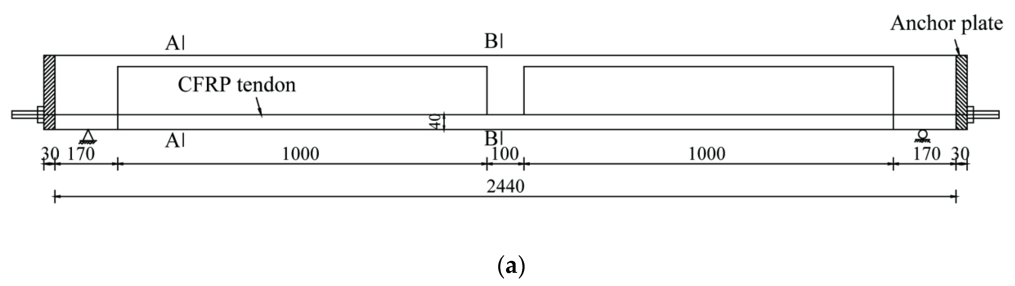
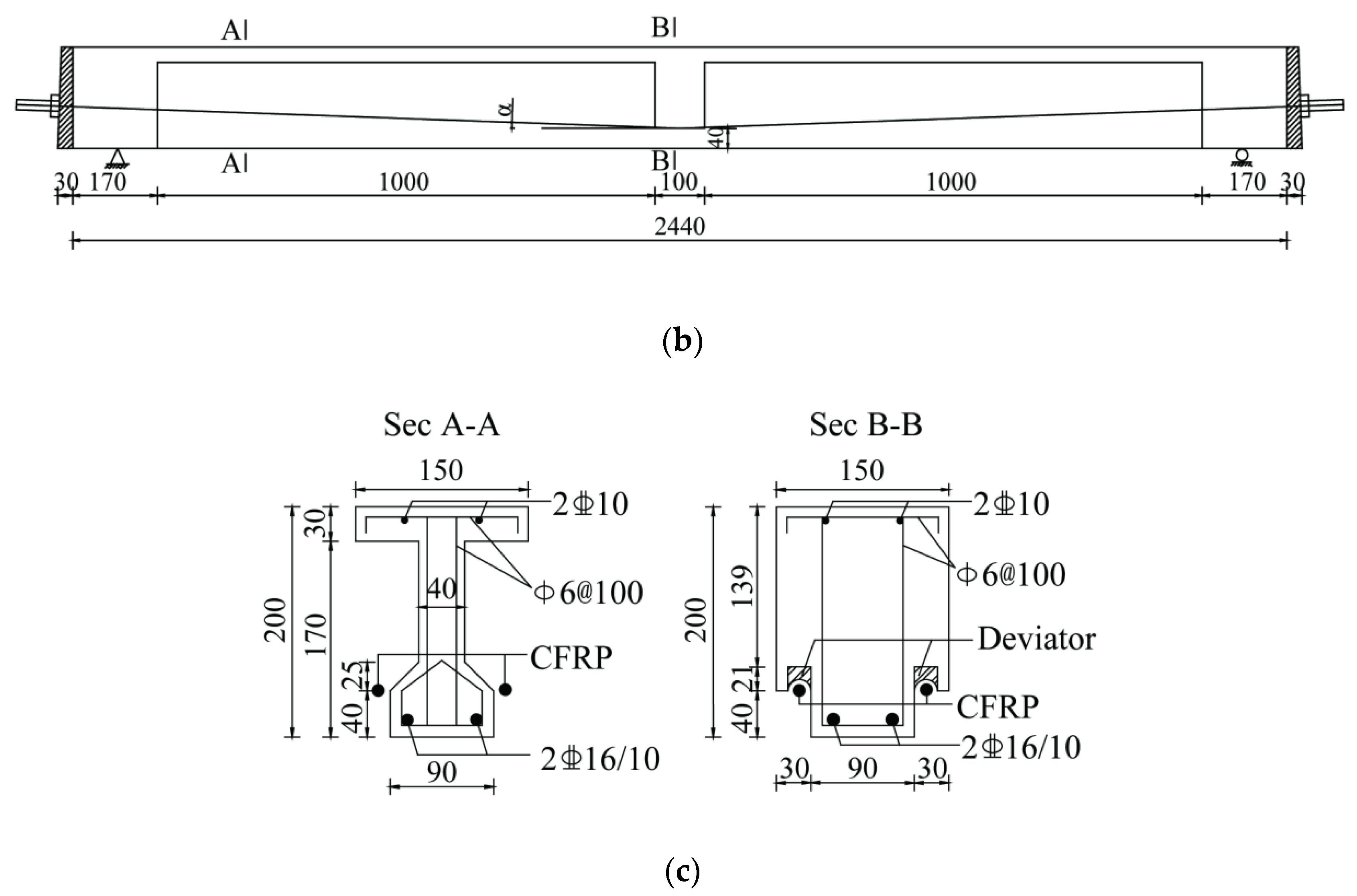
2.1. Details of Specimens

Based on a previous experimental study conducted by the authors, four new specimens were designed and tested in the present study. Thus, the total experimental program consisted of eight specimens, as listed in Table 1. The specimen code consisted of four parts, E-P-D-L, where E represented the effective prestressing stress fpe applied to the external tendons (as a percentage of the ultimate tensile strength ffp of the CFRP tendon); P was the percentage of PPR (as defined in the note of Table 1); D represented the deviated angle αp of the external tendons in midspan; L indicated the loading condition (three-point or four-point loading). Besides, according to the configuration of reinforcements, the tested beams could be divided into two groups: specimens E30-P85-D0-L3, E55-P68-D0-L3, E30-P85-D3-L3 and E30-P85-D6-L3 were partially prestressed beams with internal steel reinforcements. E30-P100-D0-L3, E45-P100-D0-L3, E55-P100-D0-L3 and E45-P100-D0-L4 were fully prestressed beams without any internal reinforcements.
All beam specimens were 2440 mm long, with a depth of 200 mm. Figure 1 depicted the typical dimensions and reinforcement layout (if existed) of the tested beams. The external CFRP tendons were anchored at the two ends of the specimen and pitted with deviators at midspan. The embedded deviators were saddle shaped with a 400 mm radius of curvature. Moreover, 6 mm steel stirrups spaced at 100 mm over the entire length of the beam were used as the shear reinforcements in the partially prestressed specimens.

2.2. Material Properties
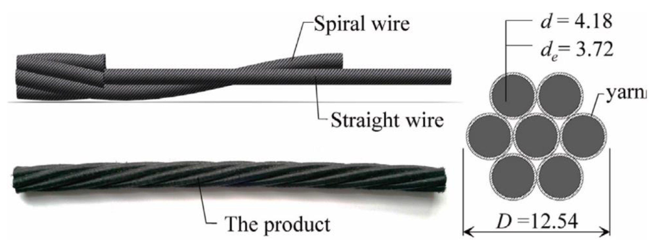
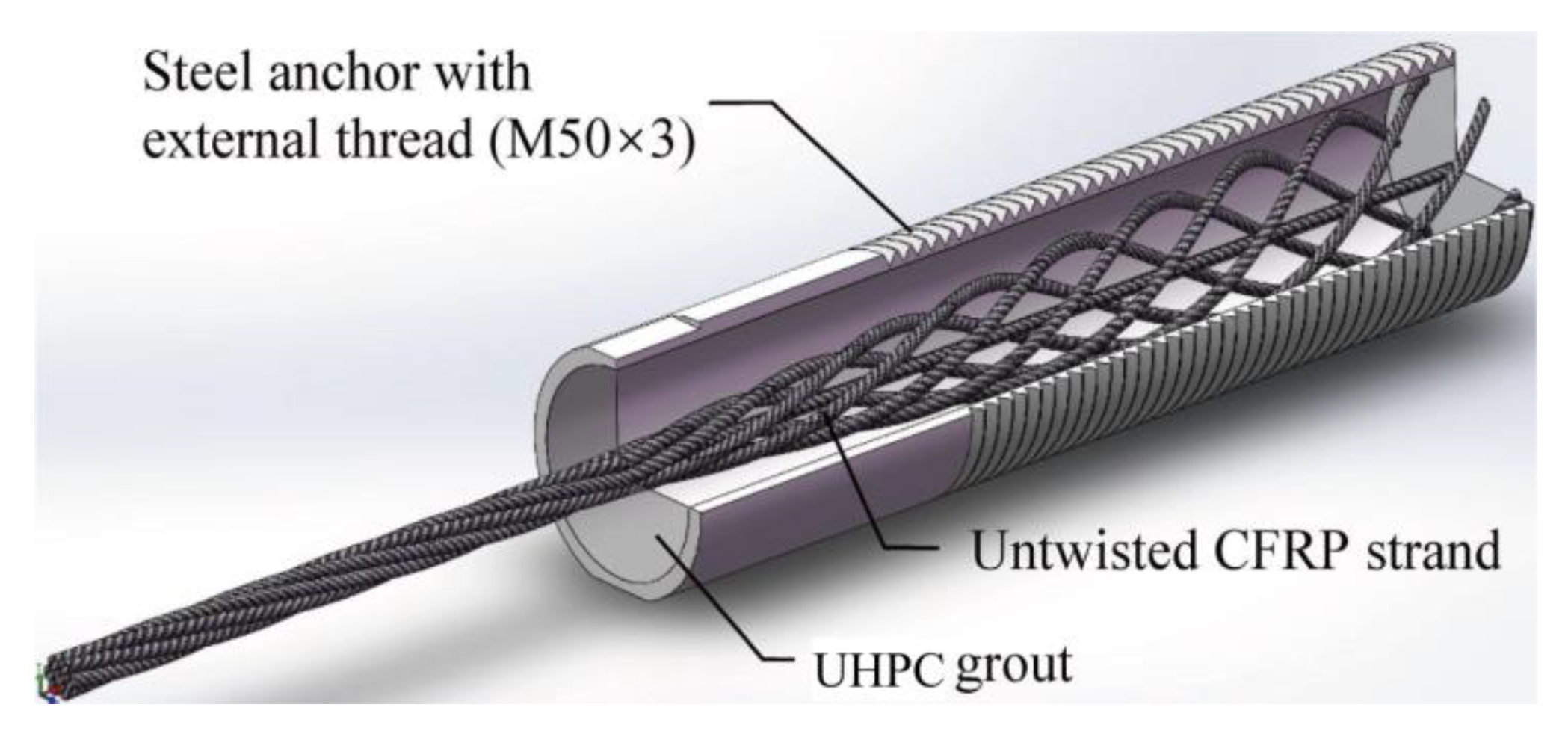
2.2.1. CFRP Tendons

The Carbon Fiber Composite Cable (CFCC®) manufactured by Tokyo Rope, Japan was used for the external tendons in the tested beams. This type of CFRP strand, with the nominal diameter D of 12.54 mm, consists of one straight wire and six twisted wires. The individual wires were fabricated through a roving prepreg process, then twisted and wrapped with a synthetic protective yarn. The nominal diameter d and the effective diameter de of each wire were 4.18 mm and 3.72 mm, respectively, as shown in Figure 2. The mechanical properties of CFRP tendons as well as steel reinforcements were included in Table 2.
The conventional anchor used for steel strands was not suitable for FRP tendons, hence a bond-type anchor developed by our group was employed [28,29]. The previous investigation indicated that a bond length of no less than 36de (approximately 150 mm) in UHPC grout could insure a satisfactory anchorage even under impact loading [28]. Thus, the bond length of CFCC® strands was conservatively adopted as 220 mm in the present study. An external tendon-anchor assembly comprised a CFCC® strand and bond-type anchors grouted with plain UHPC free of steel fibers at each end. To increase the effective contact area with the filling grout for better anchoring performance, the CFRP tendons was untwisted inside the anchor tube, as shown in Figure 3.

2.2.2. UHPC

UHPC with a 2% volume fraction of steel fibers was used to cast the beams. The quality mix proportion was cement:water:silica fume:ground quartz:quartz sand:water reducing agent = 1:0.2:0.25:0.3:1.1:2.5%. The steel fibers used in present study had a length of 13 mm, a diameter of 0.2 mm, and a tensile strength of more than 2000 MPa. The tested beams and anchors were hot-cured (24 h at room temperature followed by 72 h of steam curing at 85 ± 5 °C). The mechanical properties of UHPC at 28 d were tested as follows. The cubic compressive strength (fcu) was obtained using standard 100 mm cubes; the axial compressive strength (fc) and modulus of elasticity (Ec) were determined using 100 × 100 × 300 mm prisms; the initial cracking and ultimate tensile strengths (fr0 and fru) under flexural-tension were obtained using 100 × 100 × 400 mm prisms. Specifically, the average values of fcu, fc, fr0, fru, and Ec were 153.6 MPa, 126.1 MPa, 11.7 MPa, 24.7 MPa, and 44.7 GPa, respectively.

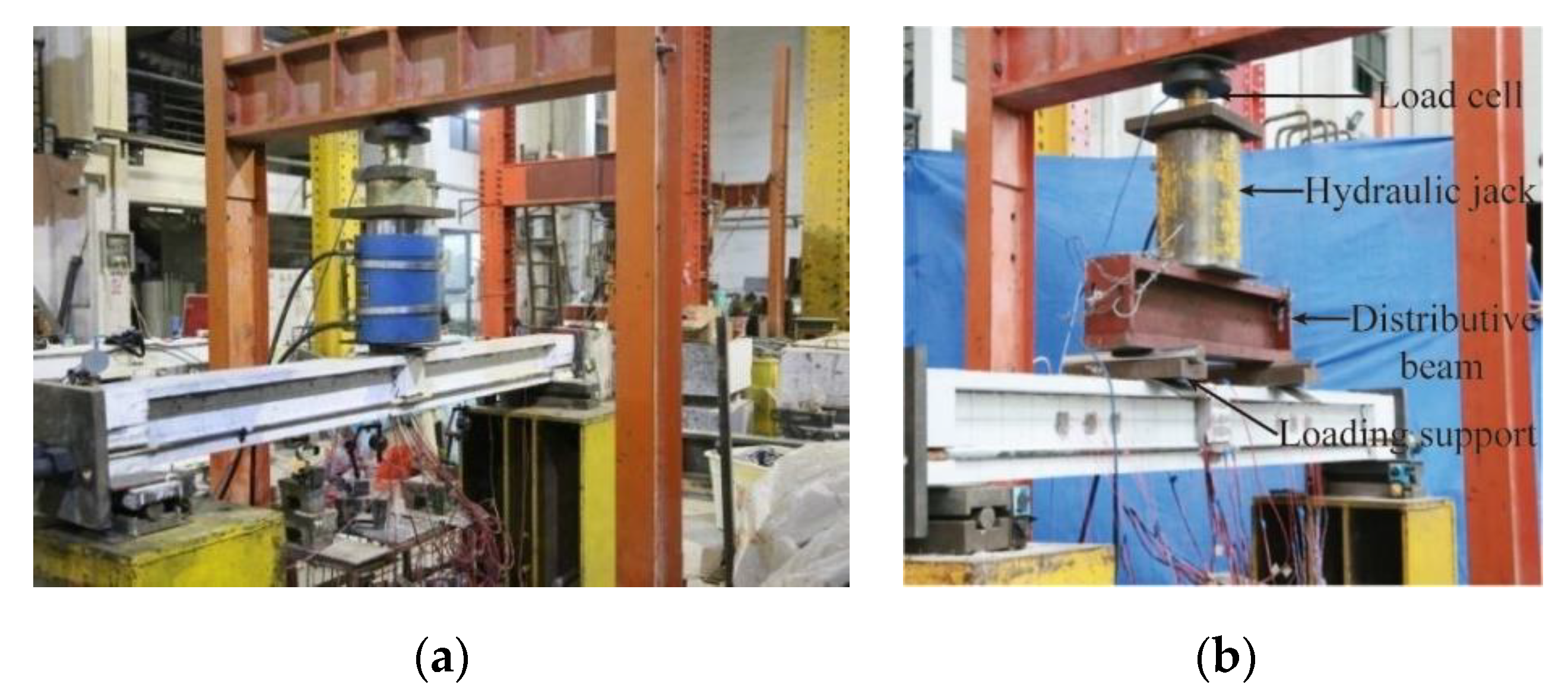
2.3. Tensioning Procedure, Loading Methods, and Measurements

To reduce local stress concentration, 30 mm thick steel anchor plates were bonded to the beam ends. The prestressing force of each external tendon was measured by a pressure sensor incorporated at the dead end of the specimen during the tension process. Moreover, a rubber protective cover was wrapped around the tendon at the deviating and anchoring positions to protect the CFRP strands. To minimize the short-term loss of the prestressing force, CFRP tendons were tensioned to an initial stress value to 1.05fpe. The total prestressing losses of no more than 2% fpe were measured before the loading process.
Specimen E45-P100-D0-L4 with a shear span to depth ratio (a/d) of 2.55 was subjected to four-point loading, whereas the other specimens with a/d of 5.65 were tested under three-point loading, details as shown in Figure 4. A hydraulic jack with a capacity of 500 kN was employed, and the load was applied in load control at a loading rate of 2.5 kN per minute. The deflections at the midspan and the supports were measured using dial indicators. The steel bar strain and concrete strain in the midspan section were measured by electrical strain gauges. The distribution of cracks was recorded manually by tracing crack propagation on the surface of the specimens, and the crack widths measured by a hand-held microscope.

3. Test Phenomena and Results
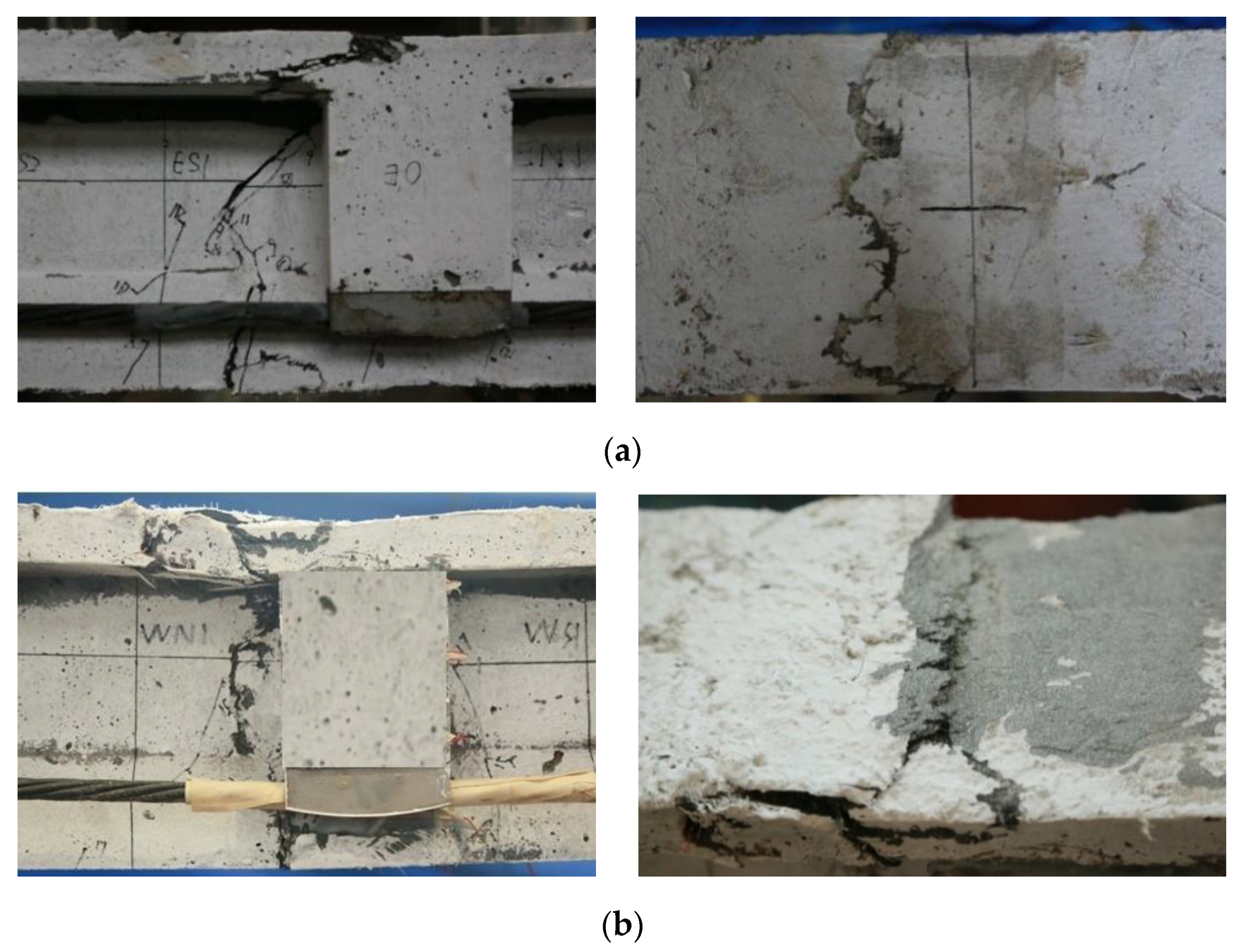
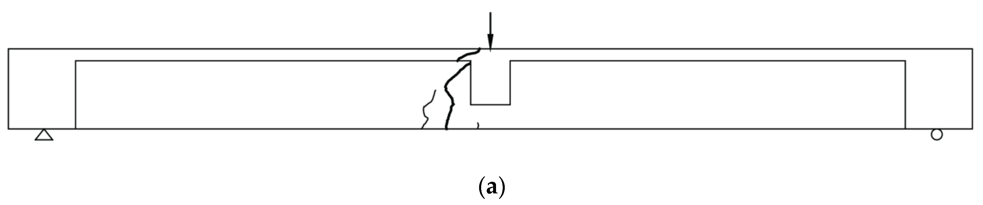
3.1. Failure Modes

Photographs of the typical failure patterns are given in Figure 5. Two different failure modes, UHPC tension failure and compression crushing, were observed. Overall, the fully prestressed beams failed in tension fracture along the critical crack in vicinity of the midspan. Whereas, the partially prestressed beams failed in compression crushing of concrete in the top flange.
For the fully prestressed beams, merely one or a few flexural cracks appeared near the midspan, where the maximum flexural moment existed. One flexural crack was gradually developed into the critical crack with the increasing load, indicating the steel fibers began to pull out from UHPC matrix in the tension zone. The critical crack widened rapidly, and propagated upward through the web. Finally, the typical tension failure occurred with little warning, and the fully prestressed specimen was divided into two parts by the critical crack. It should be noted that the total number of flexural cracks appeared during the loading procedure was limited, due to the high tensile strength of UHPC and the application of external tendons. Besides, the ultimate compression strains in the top flange varied between 1832 με (E30-P100-D0-L3) and 3313 με (E55-P100-D0-L3), which were well below the ultimate compression strain of UHPC (about 4500 με [30]). This result suggested that the compression strength of UHPC was not sufficiently mobilized in fully prestressed beam.
For the partially prestressed beams, the total number of flexural cracks was obviously increased and the cracking distribution was more uniform, because tensile steel bars were favorable to stress redistribution and restricted the propagation of major flexural cracks. A part of the major cracks extended upward with the increasing applied load. Finally, UHPC in the top flange was crushed before the fracture of steel bars and the external tendons. The measured maximum compression strains in the top flange ranged from 4723 με (E30-P85-D0-L3) to 5338 με (E55-P68-D0-L3). Therefore, due to the presence of the internal tensile reinforcements, the brittle failure of the fully prestressed beam switched to the ductile failure of the partially prestressed beam.

3.2. Load-Deflection Behavior

The main test results of eight specimens at the cracking, yielding (softening) and ultimate states are listed in Table 3. The load-deflection and moment-deflection behavior of specimens are plotted in Figure 6 and Figure 7, respectively.

3.2.1. The Fully Prestressed Specimens

Overall, the cracking load of the fully prestressed beam was mainly determined by the effective stress in CFRP tendons and the initial cracking strength of UHPC, whereas the ultimate load was mainly controlled by the ultimate stress in CFRP tendons and the tensile strength of UHPC. The load-deflection behavior of the fully prestressed beams could be roughly described into three stages:
(1)
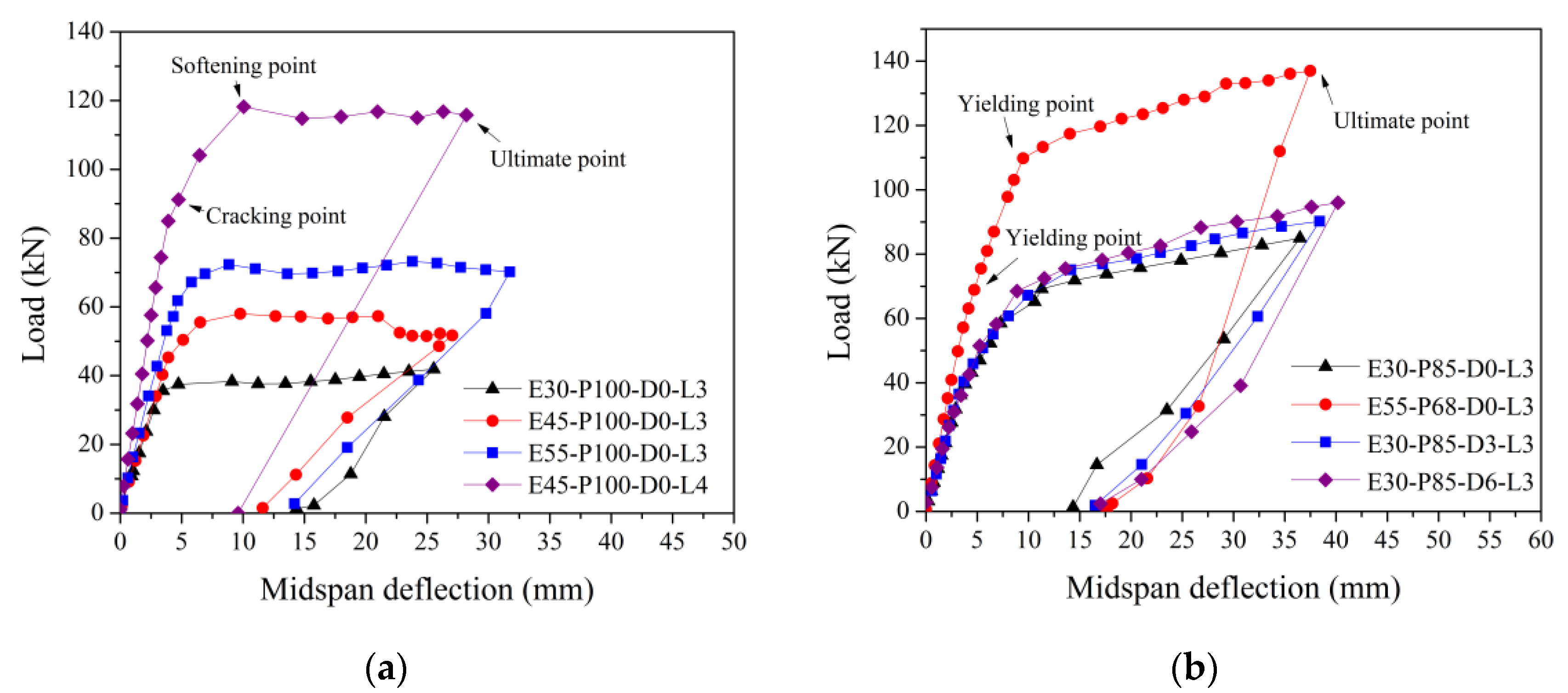
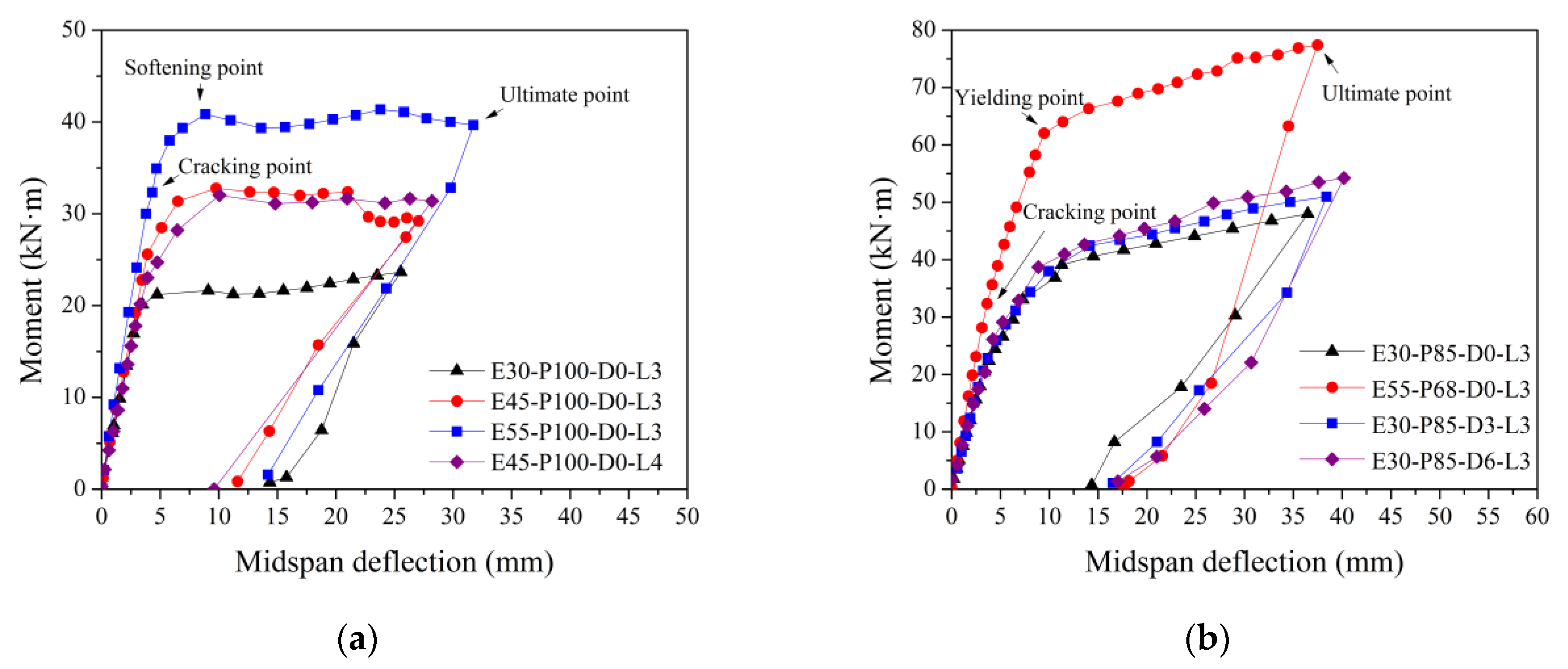
The first stage was up to the flexural cracking point, and represented the stiffness of uncracked beam section. As the applied load increased, the flexural crack appeared at the bottom of the midspan section, where the tensile strain exceeded the cracking strain of the UHPC matrix. The cracking load corresponded to the tensile strength of UHPC matrix. Due to the steel fibers across the crack and the application of CFRP tendons, the stiffness of the fully prestressed specimen did not decrease immediately after the initial cracking state.
(2)
The second stage was from the flexural cracking point to the softening point. Because the crack surfaces were bridged by closely spaced steel fibers, the flexural cracks propagated sightly during this stage. However, the steel fibers at the crack region gradually exhausted their crack-bridging effect with the increasing load, and thus the softening load was obtained when the strain in the most extreme fiber in tension reached the ultimate tensile strain of UHPC (approximately 7000 με [12]). Compared with the corresponding cracking loads, the softening loads of the fully prestressed specimens increased by 5.3% (E30-P100-D0-L3) to 29.6% (E45-P100-D0-L4). This could be attributed to the crack-bridging effect of steel fibers in the tension zone.
(3)
The third stage was from the softening point to the ultimate point. The applied load was almost constant with a rapid increasing deflection in this stage, until the brittle fracture of the specimen occurred. It indicated that the failure mode of the fully prestressed beams was a tension-controlled failure. The stress in the most extreme fiber in compression continued to increase, and the tendon stress also exhibited a continuous growth trend with increasing midspan deflection. Nevertheless, the losing tension force due to the reduction of the UHPC tension zone was significant, and thus the increased prestressing stress in the CFRP tendons were not sufficient to increase the applied load of the specimen [31]. As a result, the average value of Pu/Pcr of four fully prestressed beams were around 1.20. The load-transfer mechanism of the fully prestressed specimens in this stage was consistent with a tied-arch, and the external tendons acted as a tie rod.

3.2.2. The Partially Prestressed Specimens

The ultimate load and midspan deflection of the partially prestressed specimens were significantly enhanced, and the load–deflection curves also showed a trilinear trend:
(1)
The first stage was similar to that of the fully prestressed beams.
(2)
The middle stage was from the flexural cracking state to the yielding of the steel bars. The longitudinal steel bars could provide a high tensile force, resulting in a distributed cracking pattern on the specimens. Hence, the postcracking flexural stiffness of the specimen with internal steel bars was greatly improved. Compared to the corresponding cracking loads, the yielding loads of the partially prestressed specimens increased by 59.4% (E55-P68-D0-L3) to 66.3% (E30-P85-D3-L3). This result suggested that the postcracking flexural stiffness of the specimen with internal steel bars was significantly improved.
(3)
The final stage was from the yielding of the steel bars to the crushing of compressive flange. The midspan deflection of increased rapidly with the increasing applied load in this stage after the yielding of tensile bars. Moreover, compared to the fully prestressed beam E55-P100-D0-L3, the ultimate load and deflection of E55-P68-D0-L3 increased by 95.2% and 18.1%, respectively. Similarly, compared to E30-P100-D0-L3, the ultimate load and deflection of E30-P85-D0-L3 increased by 102.9% and 42.8%. The average value of Pu/Pcr of four partially prestressed beams were around 2.21. These results indicated that the addition of internal tensile bars significantly enhanced the flexural behavior of UHPC beams prestressed with external CFRP tendons.
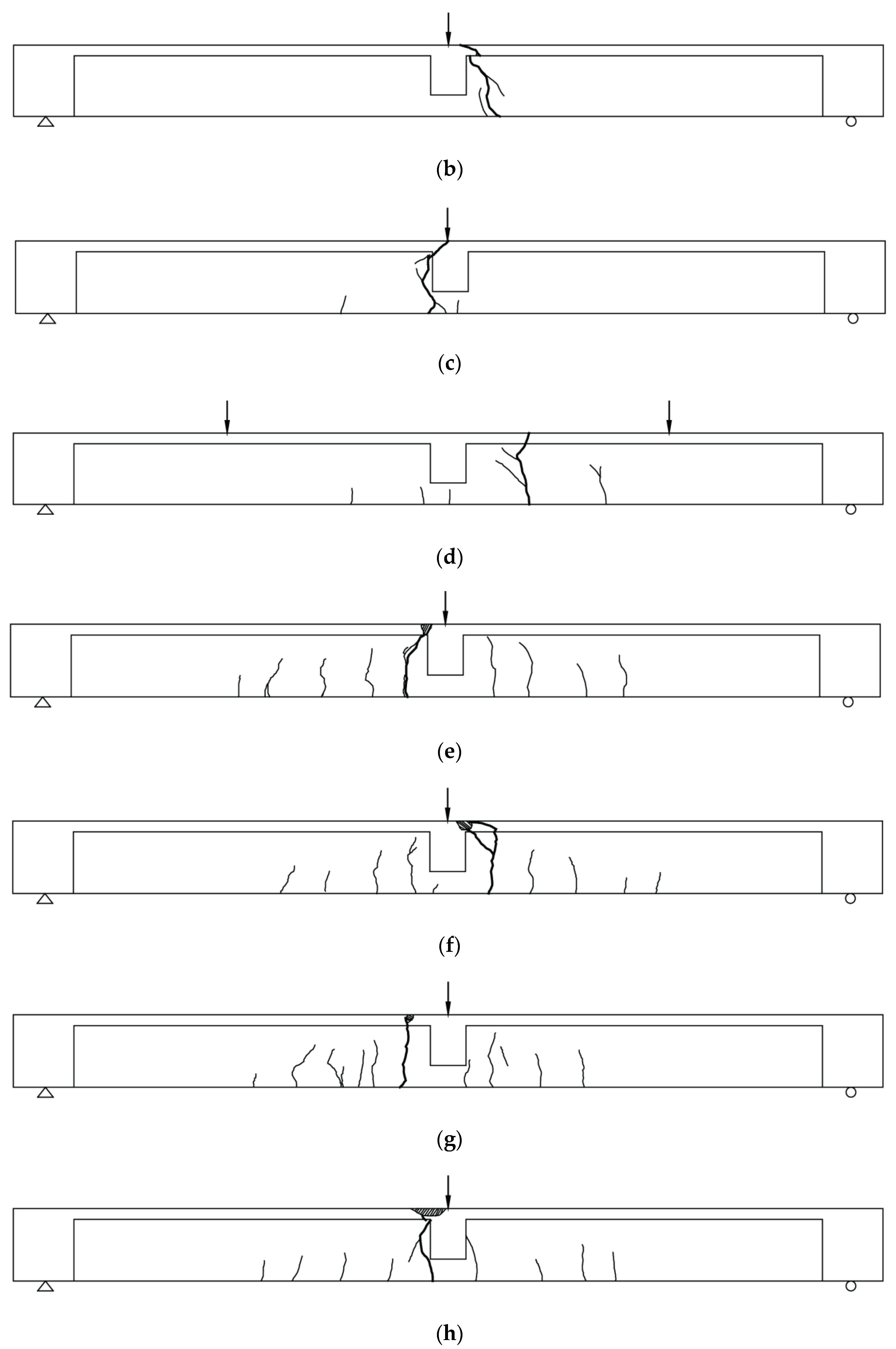
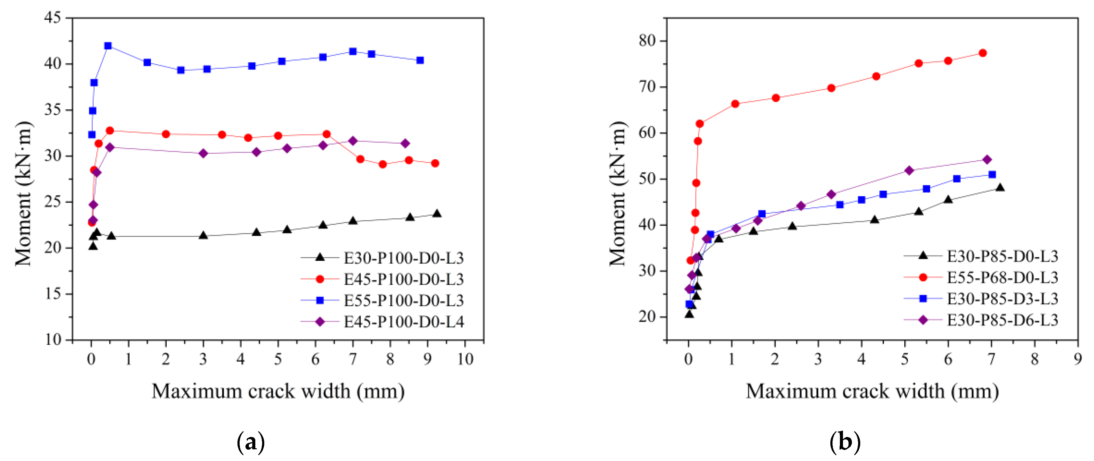
3.3. Crack Patterns

Figure 8 shows the schematic drawing of cracking patterns. The bending moment-maximum crack width relationships of the specimens are presented in Figure 9.
For the fully prestressed beams, the flexural cracking merely occurred near the midspan. Specifically, although a small amount of flexural cracks appeared within the pure bending section of the four-point loaded specimen E45-P100-D0-L4, no web-shear cracks propagated within the shear span. The maximum crack widths at the softening point were approximately 0.45 to 0.55 mm, although the applied loads were close to the ultimate loads. As mentioned above, the crack width of developed slowly before the softening point, and then increased rapidly, due to the exhausting of the crack-bridging effect. The cracking pattern of the fully prestressed beams was similar to that of an externally prestressed normal strength concrete beam with a low longitudinal reinforcement ratio. Hence, the steel fibers neither improved the distribution of flexural cracks nor restrained the propagation of flexural cracks effectively. In addition, the maximum crack widths of E30-P100-D0-L3, E45-P100-D0-L3, and E55-P100-D0-L3 were 9.25, 9.17, and 8.80 mm at failure. This illustrates that the effective prestressing stress fpe had an insignificant influence on the maximum crack width of the fully prestressed beams.
For the partially prestressed beams, a multiple cracking pattern was observed, because the addition of the steel bars resulted in a relatively uniform tensile stress distribution. The crack width slightly developed before the yielding of the steel bars, and then progressively increased. The maximum crack widths at the yielding point were approximately 0.26 to 0.34 mm, and the applied loads had exceeded 73% of the ultimate loads. Specifically, the average crack spacings of the partially prestressed beams were 133 (E30-P85-D6-L3) to 179 mm (E55-P68-D0-L3). The maximum crack widths at failure of specimens E30-P85-D0-L3, E55-P68-D0-L3, E30-P85-D3-L3 and E30-P85-D6-L3 were 7.24, 6.81, 7.02 and 6.91 mm, respectively. Compared with the fully prestressed beams, the crack propagation of the partially prestressed beams was slower, and the average maximum crack width was approximately 27% smaller. This suggested that the internal reinforcements could lead to a distributed cracking pattern, and thus decrease the maximum width of flexural cracks.

3.4. Stress Variation in CFRP Tendons

Figure 10 illustrates the relationships between the midspan deflection and the tendon stress of specimens. The stress in the external tendons was calculated from the value of the forces measured by the pressure sensors. Due to the inverted camber of the specimen induced by the prestressing force, the CFRP tendons might detaching the deviator in the midspan. Thus, the tendon stresses of specimens with horizontal tendons were usually not exactly proportional to the midspan deflection in the early stage of loading process. Overall, the variation of tendon stress was slight before flexural cracking of specimens, because the midspan deflection was limited. Then the tendon stress was approximately proportional to the midspan deflection after cracking.
The ultimate stress increments of CFRP tendons in the partially prestressed beams (491.3 to 561.7 MPa) were obviously higher than those of fully prestressed beams (328.6 to 415.0 MPa), because of the greater ultimate midspan deflection. It indicated that the presence of the tensile bars increased the ultimate stress and thus improved the utilization of CFRP tendons with remarkable tensile strength. For the fully prestressed beams, the softening load was almost equal to the peak load. The stress increments of these specimens at the softening state were no more than 85 MPa, and all below 21% of the ultimate increments. Thus, this result indicated that the stress increment had limited contribution to the flexural capacity. Figure 10a shows that as fpe of the fully prestressed specimens increased from 30%ffp to 45% and 55%ffp, the ultimate stress increased by 6.1% and 26.3%, respectively. This also could be attributed to the increased ultimate deformation of the specimen with a higher fpe.
Moreover, as an externally prestressed beam is deflected with increasing applied load, the eccentricity of the tendons between the anchorages or deviators with respect to the neutral axis of the section gradually reduced due to its lack of restraint to the beam, which is defined as the second-order effect of external tenons [24]. Compared to that of E30-P85-D0-L3, ultimate stress increments of E30-P85-D3-L3 and E30-P85-D6-L3 increased by 5.4% and 14.3%, respectively. This is because compared to that of the straight tendons with a same fpe, the deviated external tendons induced a smaller inverted camber of the specimen [32], and avoided the CFRP tendon detaching the deviator before the cracking state, which would benefit to the simultaneous work of tendons and beam. However, the free length of tendons (length between anchorage and deviator) was insignificant. Owing to the employment of the saddle-shaped deviator in the midspan, the influence of the second-order effects on the flexural behavior of externally prestressed members greatly minimized, even for the horizontal tendons. Thus, the differences in ultimate tendon stress were relatively small.

3.5. Deformability Index

Because of the linear elastic behavior of FRP tendons, the conventional ductility index based on steel-reinforced structures was not suitable for FRP-reinforced structures. Therefore, the Naaman deformability index μ can be expressed by Equation (1) [33]. In this energy-based method, the deformability represented the energy absorption ability, as shown in Figure 11.
μ = ( E tol / E el + 1 ) / 2
where Etol is the total energy, Etol = Eel + Epl; Eel is the elastic stored energy; and Epl is the plastic energy.
The Naaman deformability index μ of specimens in the present study are listed in Table 3. The average value of μ in the present study was around 2.29. As mentioned above, the deformability of fully prestressed beams was mainly determined by the compression plasticity of UHPC. Thus, the average deformability index of these specimens 2.05 was approximately 23% lower than that of the partially prestressed beams 2.52. This suggested that using internal reinforcements also significantly improved the ductility of specimens. By contrast, Au and Du [9] developed a numerical approach to predict the flexural deformation of the reinforced normal strength concrete beams prestressed with internally unbonded Parafil® Type G (AFRP) tendons. When the cylinder compression strength fc of concrete ranged from 40 to 80 MPa, PPR was 0.3 to 0.7, and fpe applied to FRP tendons varied between 0.3ffp and 0.5ffp, the average value of μ was about 1.93, and μ was below 1.80 in most cases. Hence, the comparison of UHPC beams and normal strength concrete beams prestressed with FRP tendons indicated that the presence of UHPC resulted in better deformability, which is critical to structural safety.

4. Analytical Investigation

For the innovative beam based on advanced composite materials, the prediction of the flexural capacity is certainly a critical issue. Thus, an analytical study on the partially prestressed UHPC beam with external CFRP tendons in practical applications was undertaken. The sectional analysis should be performed according to the following assumptions: (1) the plane cross section assumption is valid (except external CFRP tendons). (2) The friction between the external tendon and deviator is negligible. (3) The axial deformation of the UHPC beam induced by the prestressing force can be ignored.

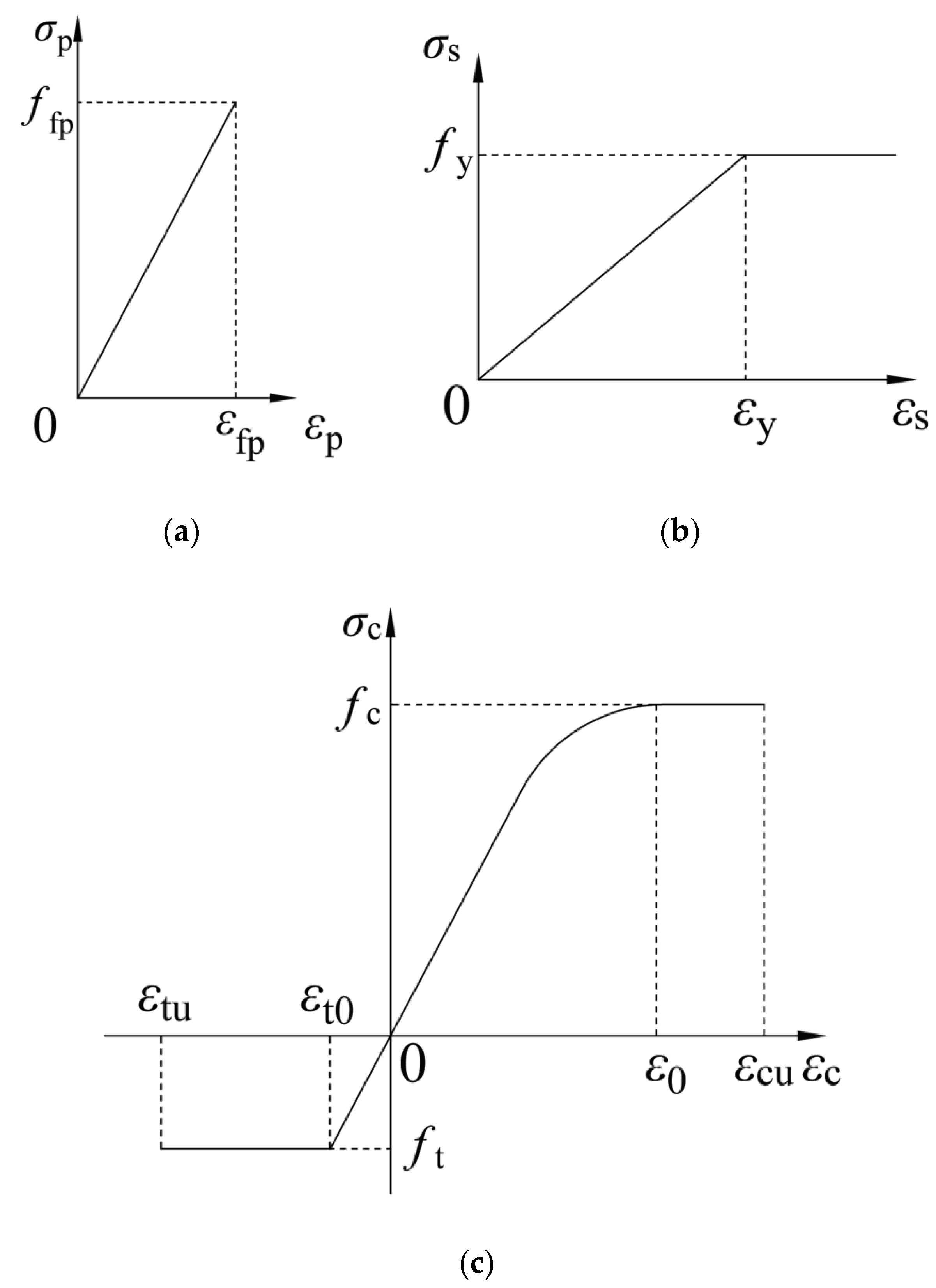
4.1. Stress–Strain Relationships of Materials

As shown Figure 12a, the CFRP tendon is considered as a linearly elastic material, which is elastic up to its ultimate strength and strain ffp and εfp. As shown Figure 12b, the steel reinforcement is assumed to be perfect elastic-plastic [26,34], where fy and εy are the yielding stress and strain, respectively. Moreover, Figure 12c shows the stress–strain relationship of UHPC. For the compression branch, the initial curve terminates at the peak compression strain ε0, where it joined a horizontal line [35]. For the tensile branch, the bilinear relationship suggested by Graybeal [36] was adopted herein.
For the compression stress σc,c-strain εc,c relationship:
σ c , c = { f c n ξ ξ 2 1 + ( n 2 ) ξ        0 ε c , c ε 0 f c                         ε 0 ε c , c ε cu
where fc is the axial compressive strength of UHPC; n = Ec/Es, where Ec is the elastic modulus of UHPC, Es is the equivalent secant modulus at peak state; ξ = εcu/ε0, where εcu is the ultimate compression strain, εcu = 4500 με [30], and ε0 is the peak compression strain, which could be adopted as 3500 με [30].
For the tensile stress σc,t-strain εc,t relationship:
σ c , t = { f t ε t ε t 0         0 ε c , t ε t 0 f t                    ε t 0 ε c , t ε tu  
where ft is the axial tensile strength of UHPC, and ft = 0.668fr0 [37]; εt0 is the peak tension strain, and εt0 = ft/Ec [36]; and εcu is the ultimate tension strain of UHPC, and εtu = 30ft/Ec [36].

4.2. Determination of Stress Increment in CFRP Tendons

Figure 13 shows the simplified calculation model of the simply supported UHPC beams prestressed with external CFRP tendons.
The deflected length of the external tendon Ls + ΔLs can be determined by a geometrical relationship, which may be written as:
L s + Δ L s = a b = ( H + δ ) 2 + ( L w + k θ u ) 2
where Ls is the initial length of the external tendon between the anchorage and the deviator; ΔLs is the elongation of CFRP tendon; H is the vertical distance from the anchorage to the deviator; δ is the deflection in midspan; Lw is the horizontal distance from the anchorage to the deviator, and L w = L s 2 H 2 ; k is the actual distance from the anchorage to the centroid of cross section of the beam-end, which could be calculated using Equation (5); and θu is the ultimate rotation angle of the beam-end.
k = h m cos β = h p x cos β
where hm is the vertical distance from the anchorage to the centroid of cross section; hp is the effective depth of external tendon at the beam-end; x is the depth of the compression zone; and β is the inclination angle of the beam-end, β = αp.
Therefore, ΔLs could be expressed as:
Δ L s = ( H + δ ) 2 + ( L w + k θ u ) 2 L s
Expanding the above equation by series and ignoring the high order derivatives [38], Equation (6) may simplify to Equation (7).
Δ L s = 2 H δ + δ 2 + 2 L w k θ u 2 L s
Subsequently, the stress increment in CFRP tendon Δfp could be written as:
Δ f p = E p Δ L s L s = ( 2 H δ + δ 2 + 2 L w k θ u ) E p 2 L s 2
Thus, the ultimate stress in CFRP tendon fpu could be calculated as:
f pu = f pe + Δ f p
where Ep is the elasticity modulus of CFRP tendons.

4.3. Determination of Ultimate Moment

Once the critical section near the midspan reaches the moment at which tension steel bars yields, a plastic hinge occurs in the partially prestressed beam. The deformations of the beam are usually concentrated on the plastic hinge length [39]. Assuming that the ultimate curvature φu is uniformly distributed within the plastic hinge length, the plastic hinge length 2 Zp, ultimate curvature φu, ultimate rotation angle θu, and ultimate midspan deflection δu may be determined by Equation (10) [40,41].
{ Z p = 0.5 h 0 + 0.05 a ϕ u = ε cu x cu θ u = Z p ϕ u δ u = ϕ u Z p 2 ( L Z p )
where h0 is the effective depth of the internal tension reinforcements; a is the length of shear span; and xcu is the depth of the compression zone at ultimate state.
Substituting Equation (10) into Equation (8), means Equation (8) would have only one unknown value.
Figure 14b,c represent the strain and stress distributions of T-shaped cross-sections at the ultimate state. Two equivalent rectangular stress blocks are applied to simplify the compression and tensile stress distribution, as shown in Figure 14d. α, β are defined as the equivalent coefficients of compression stress distribution, and κ is the equivalent coefficient of tension stress distribution. In particular, α is taken as 0.92, β is 0.74, and κ is 0.25 [27,42]. The yielding stress of steel bars under compression fy could be reasonably adopted as the yielding stress under tension fy.
Therefore, for the depth of the compression zone at ultimate state xcu > the thickness of the flange t, the force equilibrium equation can be expressed as:
α f c b w x + α f c ( b b w ) t + f y A s =   f y A s + f pu A p + κ f t b w ( h x / β )
for xcut, the force equilibrium equation is given by the following equation:
α f c b x + f y A s = f y A s + f pu A p + κ f t b w ( h x / β ) + κ f t ( b b w ) ( t x / β )
where bw is the width of the web; b is the width of the flange; As is the area of compression steel bars; As is the area of tension steel bars; Ap is the area of external CFRP tendons; and h is the depth of the cross section.
Substituting Equation (8) into the above equilibrium equations, the only unknown value could obtained. Hence, the following equations can be applied to estimate the ultimate moment of the UHPC beams prestressed with external CFRP tendons.
For xcu > t:
M u = 0.5 κ f t b w ( h 2 x 2 β 2 ) + f pu A p h p + f y A s h 0 0.5 α f c ( b b w ) t 2 0.5 α f c b w x 2 f y A y a s
For xcut:
M u = 0.5 κ f t b w ( h 2 x 2 β 2 ) + 0.5 κ f t ( b b w ) ( t 2 x 2 β 2 ) + f pu A p h p + f y A s h 0   0.5 α f c b x 2 f y A s a s
where h0 is the effective depth of the cross section; and as is the effective depth of the compression reinforcements.
The comparison between the experimental and the prediction results of the specimens are listed in Table 4. The maximum error was no more than 6%, and the average error was no more than 3%. It indicated that the proposed method could appropriately predict the ultimate moment of UHPC beams prestressed with external CFRP tendons.

5. Discussion

5.1. Effect of Effective Prestressing Stress

ACI 440.4R-04 [43] recommends that the allowable prestress level was 0.7ffp considering the creep-rupture of CFRP tendons. According to ACI 440.1R-15 [44], the stress level in CFRP tendons should be no more than 0.55ffp. Hence, E30-P100-D0-L3, E45-P100-D0-L3 and E55-P100-D0-L3 were set up to study the effect of fpe with a maximum initial stress of 0.55ffp. As shown in Figure 15, as fpe increased from 30%ffp to 45% and 55%ffp, the cracking load increased by 27.2% and 60.7%, the softening load increased by 48.0% and 93.6%, and the ultimate load increased by 23.4% and 67.5%, respectively. These obvious increases could be attributed to the compression stress provided by external tendons, which restrained the spread of cracks, avoided prematurely pulling out of steel fibers, and sustained the postcracking stiffness of the beams. For specimen E55-P68-D0-L3 with fpe = 0.55ffp, the measured maximum tendon stress reached 1838.2MPa (approximately 0.73ffp), and it did not cause any observable damages of the CFRP tendon-anchor assembly. It proved that the ACI recommend fpe in FRP tendons was reasonable, which might avoid the catastrophic failure of tendon loss.

5.2. Effect of Partial Prestressing Ratio

Au and Du [9] summarized that PPR adopted in existing literature commonly ranged from 0.3 to 0.7. In the present study, the PPR of 1.00 was designed to study the influence of steel fibers on flexural behavior, which was free from the effect of internal steel bars; the PPR of 0.68 and 0.85 were considered to represent the low non-prestressed reinforcement ratios. The partially prestressed UHPC beam with lower PPR showed significantly enhanced flexural capacity, cracking resistance and ductility. For instance, compared to those of E30-P100-D0-L3, the ultimate midspan deflection and capacity of E30-P85-D0-L3 increased by 18.1% and 102.9%. Similarly, compared to those of E55-P100-D0-L3, the ultimate midspan deflection and capacity of E55-P68-D0-L3 increased by 42.8% and 95.2%, respectively. It should be noted that the presence of internal steel bars, rather than the steel fibers in UHPC, played a critical role in determining the failure mode as well as flexural capacity of the specimens. Thus, the internal reinforcements should not be omitted from FRP prestressed UHPC beams.

5.3. Effect of Deviated Angle

ACI 440.4R-04 depicts that special deviator should be designed to consider the reduction in tensile strength of the external FRP tendons under flexural tension. Specifically, when the deviated angle is 5°, the strength reduction of CFCC® tendons, which have a curvature radius of 24D (around 300 mm), would be at most 5%ffp [43]. To investigate the flexural-tension performance of CFRP tendons cooperate with deviators in the midspan, which have a curvature radius of 32D (400 mm), three different deviated angles αp were applied in the present study. Compared to specimen E30-P85-D0-L3 with horizontal tendons, the ultimate capacity of specimens E30-P85-D3-L3 and E30-P85-D6-L3 with harped tendons merely increased by 6.1% and 12.9%, as shown in Figure 16. The deviated prestressing tendon enhanced the flexural behavior of the beams, due to the increasing ultimate stress fu in CFRP tendons. No evidence for damages at the deviating points or the tendon-anchor junctions was observed in each specimen, and thus the external CFRP prestressing system exhibited an excellent flexural-tension performance.

5.4. Effect of Loading Condition

Two loading conditions, one concentrated load (a/d = 5.65), and two concentrated loads (a/d = 2.55) were applied to evaluate the difference between bending-shear and pure bending performance in the critical section. Although the ultimate load of E45-P100-D0-L4 was much higher, its ultimate moment and midspan deflection were 101.1% and 104.3% of E45-P100-D0-L3, respectively. This suggested that the loading conditions exerted slight influence on the flexural behavior of the specimens, due to the consistent failure mode of these specimens, which was basically governed by the tensile strength of UHPC and ultimate stress in CFRP tendons.

6. Conclusions

The experimental and analytical results of UHPC beams prestressed with external CFRP tendons were presented. The following conclusions were drawn from this investigation:
(1)
The average value of energy-based deformability indexes of the specimens in the present study reached around 2.3. Hence, the application of UHPC significantly improved the deformability of FRP prestressed beams, which would benefit to structural safety.
(2)
The fully prestressed beams without internal steel showed a brittle failure pattern. The ultimate load of these beams was mainly controlled by the ultimate stress in CFRP tendons and the ultimate tensile strength of UHPC. By contrast, the partially prestressed beams, in which tensile steel bars were provided, failed in a ductile manner with greatly improved postcracking flexural capacity and deformability. The internal reinforcements, instead of steel fibers in UHPC, mainly affected the crack distribution and failure mode of specimens. Thus, the internal reinforcements should not be omitted from the prestressed UHPC beams with FRP tendons.
(3)
The flexural cracks were concentrated at one or a few locations in fully prestressed beams, whereas cracks were well distributed in the partially prestressed beams. The partially prestressed beams with a lower PPR (a smaller internal steel ratio) showed enhanced cracking resistance, flexural capacity, and deformability.
(4)
A higher effective prestressing stress in CFRP tendons was favorable for enhancing the cracking resistance and ultimate capacity. CFRP tendons with an effective prestressing stress of 0.55ffp or a deviated angle of 6° remained intact after bending tests, indicating a good flexural-tension performance of external CFRP prestressing system.
(5)
The draped CFRP tendon showed higher ultimate stress than the horizontal tendon, and thus increased the prestressing effectiveness of CFRP tendons. However, compared to that of three-point loading, the condition of four-point loading exerted a slight influence on ultimate moment and deformation.
(6)
A prediction method was proposed, which take into account the influence of steel fibers on the postcracking behavior. This method could appropriately predict the flexural capacity of UHPC beams prestressed with external CFRP tendons.

Author Contributions

Conceptualization, Z.F.; methodology, Z.F. and L.J.; Validation, L.J., Z.H., X.T. and Q.W.; Formal analysis, L.J. and Z.H.; Writing—original draft preparation, L.J., Z.H.; Writing—review and editing, L.J., Z.F. and K.P.; Supervision, Z.F. and K.P.; Project administration, Z.F.; Funding acquisition, Z.F. All authors have read and agreed to the published version of the manuscript.

Funding

This research was funded by the National Natural Science Foundation of China (Grant No.: 51938012).

Institutional Review Board Statement

Not applicable.

Informed Consent Statement

Not applicable.

Data Availability Statement

Exclude this statement.

Acknowledgments

The authors would sincerely acknowledge Wei Zhang for her language editing; Maurizio Guadagnini, Bing Tu, Yu Zhang, and Jiaxing Chen for their insightful comments and technical supports.

Conflicts of Interest

The authors declare no conflict of interest.

References

  1. Aparicio, A.C.; Ramos, G.; Casas, J.R. Testing of externally prestressed concrete beams. Eng. Struct. 2002, 24, 73–84. [Google Scholar] [CrossRef]
  2. Hartt, W.H.; Lee, S.K. Projecting corrosion-induced bridge tendon failure resulting from deficient grout: Part I–Model development and example results. Corrosion 2016, 72, 991–998. [Google Scholar] [CrossRef]
  3. Hackl, J.; Kohler, J. Reliability assessment of deteriorating reinforced concrete structures by representing the coupled effect of corrosion initiation and progression by Bayesian networks. Struct. Saf. 2016, 62, 12–23. [Google Scholar] [CrossRef]
  4. Yoo, C.-H.; Park, Y.C.; Kim, H.-K. Modeling corrosion progress of steel wires in external tendons. J. Bridg. Eng. 2018, 23, 04018098. [Google Scholar] [CrossRef]
  5. Guo, T.; Sause, R.; Frangopol, D.M.; Li, A. Time-dependent reliability of PSC box-girder bridge considering creep, shrinkage, and corrosion. J. Bridg. Eng. 2011, 16, 29–43. [Google Scholar] [CrossRef]
  6. Fang, Y.; Fang, Z.; Jiang, R.; Jiang, Z.; Zhu, D. Effect of temperature on the transverse impact performance of preloaded CFRP wire. Compos. Struct. 2020, 231, 111464. [Google Scholar] [CrossRef]
  7. Fang, Y.; Fang, Z.; Huang, D.; Jiang, Z.; Zhou, X. Experimental investigation on mechanical performance of carbon fiber reinforced polymer wire after exposure to elevated temperature. Compos. Struct. 2021, 274, 114388. [Google Scholar] [CrossRef]
  8. Terrasi, G.P.; Bisby, L.; Barbezat, M.; Affolter, C.; Hugi, E. Fire Behavior of Thin CFRP pretensioned high-strength concrete slabs. J. Compos. Constr. 2012, 16, 381–394. [Google Scholar] [CrossRef]
  9. Au, F.T.; Du, J. Deformability of concrete beams with unbonded FRP tendons. Eng. Struct. 2008, 30, 3764–3770. [Google Scholar] [CrossRef]
  10. Kahanji, C.; Ali, F.; Nadjai, A. Structural performance of ultra-high-performance fiber-reinforced concrete beams. Struct. Concr. 2017, 18, 249–258. [Google Scholar] [CrossRef]
  11. Yang, I.H.; Joh, C.; Kim, B.-S. Structural behavior of ultra high performance concrete beams subjected to bending. Eng. Struct. 2010, 32, 3478–3487. [Google Scholar] [CrossRef]
  12. Yoo, D.-Y.; Yoon, Y.-S. Structural performance of ultra-high-performance concrete beams with different steel fibers. Eng. Struct. 2015, 102, 409–423. [Google Scholar] [CrossRef]
  13. Kang, S.-T.; Kim, J.-K. Investigation on the flexural behavior of UHPCC considering the effect of fiber orientation distribution. Constr. Build. Mater. 2012, 28, 57–65. [Google Scholar] [CrossRef]
  14. Zhu, H.; Cheng, S.; Gao, D.; Neaz, S.M.; Li, C. Flexural behavior of partially fiber-reinforced high-strength concrete beams reinforced with FRP bars. Constr. Build. Mater. 2018, 161, 587–597. [Google Scholar] [CrossRef]
  15. Yoo, D.-Y.; Banthia, N.; Yoon, Y.-S. Predicting service deflection of ultra-high-performance fiber-reinforced concrete beams reinforced with GFRP bars. Compos. Part B Eng. 2016, 99, 381–397. [Google Scholar] [CrossRef]
  16. Shafieifar, M.; Farzad, M.; Azizinamini, A. A comparison of existing analytical methods to predict the flexural capacity of Ultra High Performance Concrete (UHPC) beams. Constr. Build. Mater. 2018, 172, 10–18. [Google Scholar] [CrossRef]
  17. ACI Committee. Building Code Requirements for Structural Concrete ACI 318-14; American Concrete Institute Committee 318: Farmington Hills, MI, USA, 2014. [Google Scholar]
  18. ACI Committee. Design Considerations for Steel Fiber Reinforced Concrete ACI 544.4R-1988 (R2009); American Concrete Institute Committee 544: Farmington Hills, MI, USA, 2014. [Google Scholar]
  19. FHWA. Design Guide for Precast UHPC Waffle Deck Panel System, Including Connections FHWA-HIF-13-032; Federal Highway Administration: Washington, DC, USA, 2013. [Google Scholar]
  20. Grace, N.F.; Abdei-Sayed, G. Behavior of externally draped CFRP tendons in prestressed concrete bridges. PCI J. 1998, 43, 88–101. [Google Scholar] [CrossRef]
  21. Atutis, M.; Valivonis, J.; Atutis, E. Analysis of serviceability limit state of GFRP prestressed concrete beams. Compos. Struct. 2015, 134, 450–459. [Google Scholar] [CrossRef]
  22. Atutis, M.; Valivonis, J.; Atutis, E. Deflection determination method for BFRP prestressed concrete beams under fatigue loading. Compos. Struct. 2019, 226, 111182. [Google Scholar] [CrossRef]
  23. Atutis, M.; Valivonis, J.; Atutis, E. Experimental study of concrete beams prestressed with basalt fiber reinforced polymers. Part I: Flexural behavior and serviceability. Compos. Struct. 2018, 183, 114–123. [Google Scholar] [CrossRef]
  24. Tran, D.T.; Pham, T.M.; Hao, H.; Chen, W. Numerical study on bending response of precast segmental concrete beams externally prestressed with FRP tendons. Eng. Struct. 2021, 241, 112423. [Google Scholar] [CrossRef]
  25. Ghallab, A.; Beeby, A.W. Factors affecting the external tendon stress in externally strengthened prestressed concrete beams. Cem. Concr. Compos. 2005, 27, 945–957. [Google Scholar] [CrossRef]
  26. Wang, X.; Shi, J.; Wu, G.; Yang, L.; Wu, Z. Effectiveness of basalt FRP tendons for strengthening of RC beams through the external prestressing technique. Eng. Struct. 2015, 101, 34–44. [Google Scholar] [CrossRef]
  27. Fang, Z.; Huang, Z.M.; Jia, L. Experimental research on flexural behavior of RPC beams prestressed with external CFRP tendons. J. Hunan Uni. (Nat. Sci.) 2021, 48, 103–112. [Google Scholar]
  28. Xiang, Y.; Fang, Z.; Wang, C.; Zhang, Y.; Fang, Y. Experimental investigations on impact behavior of CFRP cables under pretension. J. Compos. Constr. 2017, 21, 04016087. [Google Scholar] [CrossRef]
  29. Xiang, Y.; Fang, Z.; Fang, Y. Single and multiple impact behavior of CFRP cables under pretension. Constr. Build. Mater. 2017, 140, 521–533. [Google Scholar] [CrossRef]
  30. Yang, J.; Fang, Z.; Dai, G.L. Flexural behavior of prestressed UHPC beams. Adv. Mater. Res. 2011, 243, 1145–1155. [Google Scholar] [CrossRef]
  31. Dogu, M.; Menkulasi, F. A flexural design methodology for UHPC beams post-tensioned with unbonded tendons. Eng. Struct. 2020, 207, 110193. [Google Scholar] [CrossRef]
  32. Tan, K.H.; Ng, C.K. Effects of deviators and tendon configuration on behavior of externally prestressed beams. ACI Struct. J. 1997, 94, 13–21. [Google Scholar]
  33. Naaman, A.E.; Jeong, M. Structural ductility of concrete beams prestressed with FRP. In Non-Metallic (FRP) Reinforcement for Concrete Structures, Proceedings of the 2nd International RILEM Symposium (FRPRCS-2); CRC Press: Ghent, Belgium, 1995; pp. 379–386. [Google Scholar]
  34. Lou, T.; Lopes, S.M.; Lopes, A.V. Numerical analysis of behaviour of concrete beams with external FRP tendons. Constr. Build. Mater. 2012, 35, 970–978. [Google Scholar] [CrossRef]
  35. Lok, T.-S.; Pei, J.-S. Flexural behavior of steel fiber reinforced concrete. J. Mater. Civ. Eng. 1998, 10, 86–97. [Google Scholar] [CrossRef]
  36. Graybeal, B.A. Characterization of the Behavior of Ultra-High Performance Concrete. Ph.D. Thesis, University of Maryland, College Park, MD, USA, 2005. [Google Scholar]
  37. AFGC-SETRA. Ultra-High Performance Fibre-Reinforced Concrete Recommendations: Revised Edition; AFGC&SETRA Working Group: Paris, France, 2013; pp. 1–175. [Google Scholar]
  38. Zhang, Z.X.; Zhang, Y.T. Theoretical and experimental study on stress increment of external tendons in external prestressed concrete flexural members at ultimate state. J. Railw. Eng. Soc. 2003, 80, 75–79. [Google Scholar]
  39. Kim, K.S.; Lee, D.H. Nonlinear analysis method for continuous post-tensioned concrete members with unbonded tendons. Eng. Struct. 2012, 40, 487–500. [Google Scholar] [CrossRef]
  40. Harajli, M.H. Effect of span-depth ratio on the ultimate steel stress in unbonded prestressed concrete members. ACI Struct. J. 1990, 87, 305–312. [Google Scholar]
  41. Bin, N.I.U. Ultimate analysis of externally prestressed concrete beams. China Civ. Eng. J. 2000, 33, 7–15. [Google Scholar]
  42. Zheng, W.; Li, L.; Lu, S. Experimental research on mechanical performance of normal section of reinforced reactive powder concrete beam. J. Build. Struct. 2011, 32, 125–134. [Google Scholar]
  43. ACI Committee. Prestressing Concrete Structures with FRP Tendons ACI 440.4R-04; American Concrete Institute Committee 440: Farmington Hills, MI, USA, 2004. [Google Scholar]
  44. ACI Committee. Guide for the Design and Construction of Structural Concrete Reinforced with Fiber-Reinforced Polymer (FRP) Bars ACI 440.1R-15; American Concrete Institute Committee 440: Farmington Hills, MI, USA, 2015. [Google Scholar]
Figure 1. Dimensions and cross section of specimens (dimensions in mm): (a) layout of specimens with horizontal tendons; (b) layout of specimens with deviated tendons; (c) details of section A-A and B-B for partially prestressed beams.
Applsci 11 09189 g001aApplsci 11 09189 g001b
Figure 2. Details of CFRP tendons.
Applsci 11 09189 g002
Figure 3. Details of the bond-type anchor.
Applsci 11 09189 g003
Figure 4. View of test setup: (a) three-point loading; (b) four-point loading.
Applsci 11 09189 g004
Figure 5. Typical failure patterns of specimens: (a) tension controlled failure of the fully prestressed specimen; (b) compression controlled failure of the partially prestressed specimen.
Applsci 11 09189 g005
Figure 6. Load-deflection relationships of specimens: (a) the fully prestressed specimens; (b) the partially prestressed specimens.
Applsci 11 09189 g006
Figure 7. Moment–deflection relationships of specimens: (a) the fully prestressed specimens; (b) the partially prestressed specimens.
Applsci 11 09189 g007
Figure 8. Cracking patterns of specimens: (a) E30-P100-D0-L3; (b) E45-P100-D0-L3; (c) E55-P100-D0-L3; (d) E45-P100-D0-L4; (e) E30-P85-D0-L3; (f) E30-P85-D3-L3; (g) E30-P85-D6-L3; (h) E55-P68-D0-L3.
Applsci 11 09189 g008aApplsci 11 09189 g008b
Figure 9. Moment–maximum crack width relationships of beams: (a) fully prestressed specimens; (b) partially prestressed beams.
Applsci 11 09189 g009
Figure 10. Tendon stress–deflection relationships of specimens: (a) fully prestressed specimens; (b) partially prestressed specimens.
Applsci 11 09189 g010
Figure 11. Schematic description of ductility index.
Applsci 11 09189 g011
Figure 12. Stress–strain relationships of materials: (a) stress–strain relationship of CFRP; (b) stress–strain relationship of steel; (c) stress–strain relationship of UHPC.
Applsci 11 09189 g012
Figure 13. Calculation model of specimens.
Applsci 11 09189 g013
Figure 14. Stress–strain distribution at ultimate state: (a) cross section drawing; (b) strain distribution; (c) actual stress distribution; (d) simplified triangular stress distribution.
Applsci 11 09189 g014
Figure 15. The influence of fpe on flexural capacity.
Applsci 11 09189 g015
Figure 16. The influence of αp on flexural capacity.
Applsci 11 09189 g016
Table 1. Details of specimens.
Specimen CodeSteel Area (mm2)PPR
(%)
fpe
(MPa)
αp
(°)
Loading ConditionNote
LowerUpper
E30-P85-D0-L315715785778.50Three-pointPartially
prestressed beams
E30-P85-D3-L315715785786.43Three-point
E30-P85-D6-L315715785714.36Three-point
E55-P68-D0-L3 *402157681334.90Three-point
E30-P100-D0-L3--100775.80Three-pointFully
prestressed beams
E45-P100-D0-L3 *--1001023.00Three-point
E45-P100-D0-L4 *--1001032.90Four-point
E55-P100-D0-L3 *--1001358.60Three-point
Note: * The specimens tested by the authors in a previous study [27]; and PPR = Apffp/(Apffp + Asfy), where Ap is the area of the CFRP tendons; As is the area of tensile steel bars; and fy is the yield strength of tensile steel bars.
Table 2. Material properties of reinforcements.
Material TypeNominal Diameter D (mm)Modulus of Elasticity E (GPa)Yielding Strength fy (MPa)Yielding Strain εsy (με)Tensile Strength ffp (MPa)Elongation at Ultimate (%)
Steel bar type 116210451214859325.6
Steel bar type 210200447223558123.3
Steel stirrup6200321160544220.1
CFCC® tendon12.54157--25391.6
Table 3. Experimental results for specimens.
Specimen CodeCracking StateYielding/Softening StateUltimate StatePy(Ps)/PcrPu/Pcrμ
Pcr (kN)Δcr (mm)Py/Ps (kN)Δys (mm)Pu (kN)Δu (mm)
E30-P85-D0-L336.23.3658.57.2885.036.481.622.352.48
E30-P85-D3-L340.43.7067.29.9590.238.401.662.232.52
E30-P85-D6-L342.64.2368.58.8996.040.191.612.252.51
E55-P68-D0-L368.94.72109.89.47137.037.481.591.992.57
E30-P100-D0-L335.63.4837.54.7441.925.541.051.182.01
E45-P100-D0-L345.33.9155.56.5151.727.051.231.142.10
E45-P100-D0-L491.24.75118.210.06115.828.211.301.272.01
E55-P100-D0-L357.24.3272.68.8670.231.731.271.232.08
Note: Pcr and Δcr denote the cracking load and midspan deflection; Py and Δy represent the yielding load and midspan deflection of partially prestressed beam; Ps and Δs denote the softening load and midspan deflection of fully prestressed beams; Pu and Δu represent the ultimate load and midspan deflection; and μ is Naaman deformability index (as defined in Section 3.5).
Table 4. The comparison of experimental and predicted results.
Specimen CodeMu,e (kN·m)Mu,p (kN·m)Mu,e /Mu,p
E30-P85-D0-L348.050.20.96
E30-P85-D3-L351.054.20.94
E30-P85-D6-L354.256.60.96
E55-P68-D0-L377.474.91.03
Mean--0.97
Standard deviation--0.03
Note: Mu,e is the experimental ultimate moment; and Mu,p is the predicted ultimate moment.
Publisher’s Note: MDPI stays neutral with regard to jurisdictional claims in published maps and institutional affiliations.

