Article

Development of an Intelligent Voltage Control System for Bulk Power Systems

1
Department of Electrical Engineering, Kwangwoon University, Seoul 01897, Korea
2
Department of Automatic Electrical Engineering Technology, Yeungnam University College, Daegu 42415, Korea
3
Department of Robotics, Kwangwoon University, Seoul 01897, Korea
4
Department of Electronic Convergence Engineering, Kwangwoon University, Seoul 01897, Korea
*
Author to whom correspondence should be addressed.
Appl. Sci. 2021, 11(19), 9233; https://doi.org/10.3390/app11199233
Submission received: 26 July 2021 / Revised: 22 September 2021 / Accepted: 28 September 2021 / Published: 4 October 2021
(This article belongs to the Special Issue Artificial Intelligence for Power System Applications)

Abstract

:
As modern power systems become large and complicated, an automated voltage and reactive power control system is required in most developed countries due to the remarkable recent progress in computer networks and information technology. To date, voltage control has depended on human operators in the Korean power system. Accordingly, this paper proposes a universal intelligent voltage control system for bulk power systems based on sensitivity analysis and a main expert system. A detailed state space modeling technique is discussed, and an effective performance index is proposed to accelerate the searching performance of the expert system. As the searching strategy is an important factor for the speed of the expert system, the least-first search algorithm is applied using this performance index. The proposed system has been applied to the Korean power system, showing promising results.

1. Introduction

As power systems grow, many countries experience a number of widespread power outages due to voltage instability caused by the imbalance between reactive power supply and demand [1]. It is also expected that voltage instability will intensify in the near future as new renewable energy sources, such as wind power plants and small solar energy systems, are expanded [2]. Therefore, maintaining adequate voltage and reactive power is becoming an important issue in most countries.
The voltage control methodology in bulk power systems can be classified into numerical methods and intelligent system approaches. The hierarchical-distributed architecture was first proposed by the French company Électricité de France [3]. This system consists of three layers of architecture: primary voltage control, secondary voltage control, and tertiary control [4]. Italy proposed a similar three-layer architecture, which consists of primary voltage regulation regional voltage regulators and tertiary voltage regulators [5]. Spain’s voltage control system also consists of three layers of architecture [6]. Therefore, a hierarchical numerical control system is widely used in European countries. Of course, the detailed object function and operational strategy are different depending on the situation of each country. An interesting point in the secondary voltage control is the pilot node, which is most important to coordinate the regional voltage as it represents the center of the regional load. The pilot node concept may reduce the remote sensing cost and calculation burden. However, it may be hard to select pilot nodes in some tightly coupled power systems.
For intelligent voltage control systems, the sensitivity tree-based real-time voltage and reactive power control method was proposed for the first time in Canada [7] in the 1980s. In the 1990s, SEGRE [8] and SETRE [9,10] were proposed in Spain, which are basically hybrid systems using the sensitivity tree-based numerical computation and artificial intelligence method using operators’ knowledge [11,12]. However, the detailed numerical modeling and structure of the expert system, such as the knowledge-based, searching-space, and inference technique, have not been reported yet.
In Korea, the voltages of load buses have been maintained by human operators based on their experience at regional locations. However, especially in metropolitan areas, it has been difficult to secure enough sites to install reactive power compensation equipment. In addition, voltage fluctuations frequently occur due to increased reactive power demands, such as underground cables. Therefore, a modern control system is required to maintain the entire system voltage.
Recently, a secondary voltage control system [13,14] has been proposed in Korea. This system has been tested in a test-bed system in Jeju Island. However, as the total power generation capacity has exceeded 125 GW in Korea, and Korea’s main power system is very tightly coupled internally, a pilot node selection would be difficult for the mainland power system. Presently, it is clear that the supervisory control and data acquisition (SCADA) or remote sensing cost becomes increasingly cheaper. As Korea’s mainland power system has a complex structure with heavy load density, an intelligent control approach would be more efficient than a conventional hierarchical three-layer approach. Therefore, an intelligent system has been proposed [15,16,17].
This paper presents a state-of-the-art intelligent voltage control system for Korea’s power system in detail. The proposed system consists of a numerical subsystem and a main expert system. The numerical subsystem consists of sensitivity matrices and power flow. The sensitivity tree space is generated by the sensitivity of various reactive power sources, such as the terminal voltage of each generator, shunt capacitors and shunt reactors, and transformer tap. The main expert system searches the sensitivity tree to find the best solution step-by-step and suggests the final control sequences.

2. Intelligent Voltage Control System

The basic structure of the intelligent voltage control system proposed herein is shown in Figure 1.
The system continuously monitors the bus voltages of the power system from an external real-time database, and when abnormal voltages occur, the system generates a control solution. The control outputs may be automatic signals or a suggestive direction to human operators depending on the installation condition of the automation facility. The main expert system was developed using the PROLOG language. Although PROLOG is a primitive language, it is powerful and easy to link with numerical subsystems. As for the inference, the backward-reasoning method was applied, which is more advantageous in most power system applications.

2.1. Sensitivity Matrices for Reactive Power Devices

The expert system uses sensitivity matrices to predict voltage fluctuations for the application of various reactive power units. It is clear that experienced human operators would be aware of the voltage impact of each reactive power device at the site.
The basic formula for identifying the relationship between the control amount and voltage violation is as follows. The reactive power in the i -th bus is expressed by the following power equations:
Q i = Q G i + Q L i + Q T i = 0   i = 1 , 2 , , n
Q T i = j = 1 n V i V j y i j s i n ( δ i δ j γ i j )   i = 1 , 2 , , n
where Q G i , Q L i , and Q T i are the reactive power of the generator, load, and transmission respectively, in the i -th bus.
The vector function and state variable for the bus voltage and control equipment are respectively defined as follows:
X = V 1 , V 2 , V 3 , V n T , U = U 1 , U 2 , U 3 , U n T
H i = Q G i + Q L i + j = 1 n V i V j y i j sin ( δ i δ j γ i j ) , i = 1 , 2 , ,   n
Then, at a normal steady state, X   = X 0   ,   U =   U 0 ,
H X 0   ,   U 0 = 0
If some violation occurs, then the perturbation equation is:
H X 0   + Δ X ,   U 0 + Δ U = 0
Through a Taylor series expansion, the linearized equation is obtained:
H X 0   ,   U 0 + H X X 0   ,   U 0 Δ X + H U X 0   ,   U 0 Δ U = 0
Therefore,
Δ X = S ·Δ U ,   where   S = H X 1 · H U
Here, S is the sensitivity matrix for the control variable U.
In the proposed system, we considered the generator terminal voltage, shunt capacitor, shunt reactor, and tap of the on-load tap changer (OLTC) as the control devices. Therefore, the sensitivity matrices for each control device are represented as follows:
Δ X = S V g · Δ U Vg
Δ X = S T · Δ U T
Δ X = S s h · Δ U sh
where S V g , S T , and S s h are the sensitivity matrices for the generator terminal voltages, OLTC tap, and shunt capacitors or reactors respectively, and Δ U V g , Δ U T , and Δ U sh are the control input of the generator terminal voltages, OLTC tap, and shunt capacitors or reactors, respectively.
Since the induction process of the sensitivity matrix is rather long and complex, detailed derivation processes and final expressions will be presented in a subsequent paper [18].

2.2. Knowledge Base of the Expert System

Knowledge in an expert system is classified according to facts and rules, which are stored in the database and rule base, respectively. The database in the backward rule-based system, i.e., PROLOG, is divided by the static database and dynamic database and stored as immutable facts in a specific domain or hypothetical facts derived from the inference process. Here, the knowledge base stores the system information obtained from the load flow and uses it for searches and inferences. The contents of the database and rule base are as follows:
(A) Static and dynamic database:
  • Open/closed status of transmission lines.
  • Upper and lower limits of each bus voltage.
  • Installed capacity of each reactive power compensation device.
  • Current usable capacity of each reactive power compensation device.
  • Dynamic data from SCADA or any other monitoring system.
  • Values of the sensitivity matrices, which are functions of each bus voltage and tap position, calculated from the numerical subsystem at the request of the inference engine.
  • Load bus voltage profile calculated from the load flow.
(B) Rule base:
  • Rules to compare the current voltages with their specified limits and to find the buses with voltage violations.
  • Rules to check the voltage violation according to the following criteria:
    * Normal voltage (p.u.): 0.95 ≤ V ≤ 1.05
    * Abnormal voltage (p.u.): V < 0.95 or V > 1.05
  • Like many other countries, a ±5% variation is allowed in 765 and 345 kV high-voltage transmission networks in Korea. These limits can be changed using input data for general purposes.
  • Rules to establish the sensitivity tree for each abnormal bus voltage find the most effective (highest weighted sensitivity) control in the bus with the worst voltage violation, and calculate the controls needed to remove the voltage violation.
  • Rules to check the operation of the controller considering its constraints. If the controls exceed the limits, then the control value is fixed to the control limit.
  • The criteria of the generator terminal voltage: upper and lower limits of the generator terminal voltage (p.u.).
  • Transformer tap and shunt capacitors or reactors operated in the range of control limits.
  • According to the selected control actions, voltage variations at each bus are estimated using the sensitivity tree, and the bus voltages recalculated by the load flow are refreshed under the appropriate control actions.
  • The above procedures are repeated for each load bus in the overall system until all bus voltages satisfy their own limits.

2.3. State-Space Modeling of the Voltage Control Problem

In this paper, the weighted evaluation function, as in (12), was applied to improve the performance of the developed intelligent voltage control system. It is possible to minimize the weighted evaluation function (12) when all the compensation devices use a discrete control quantity.
min ( λ V v i o + α Δ V g i + β Δ T K + γ Δ Q i ) [      λ      γ    β α   ]
V v i o is a newly occurred abnormal bus voltage in the normal bus.
Basically, the transformer tab and the switched shunt used discrete quantities. However, compensation devices, such as the generator terminal voltage, used continuous quantity. Therefore, continuous quantities, such as the generator terminal voltage, must be converted to discrete quantities via a quantization process. Figure 2 presents a partially expanded state-space model of discrete effect quantity in a power system composed of two devices (e.g., generator, transformer, switched shunt).

2.4. Least-Cost Search

After a given problem is defined in the representation model, we need a strategy to solve it, and one of the key strategies is search. The searches will be defined by the trial process to assess possible solution paths and reach from initial state to final state. They may be divided into two categories: blind searches and heuristic searches. The blind searches are divided into breadth-first search and depth-first search. However, this method is not suitable for cases in which the state-space is large because it does not contain an intelligent decision. Heuristic searches are methods to continuously search a solution after eliminating the solution path that seems inappropriate by judgment, such as heuristic knowledge or cost function. This method could reduce state-space but might not provide a solution.
In this paper, a least-cost search is used to minimize the weighted evaluation function, such as in Equation (12). The search process is as follows:
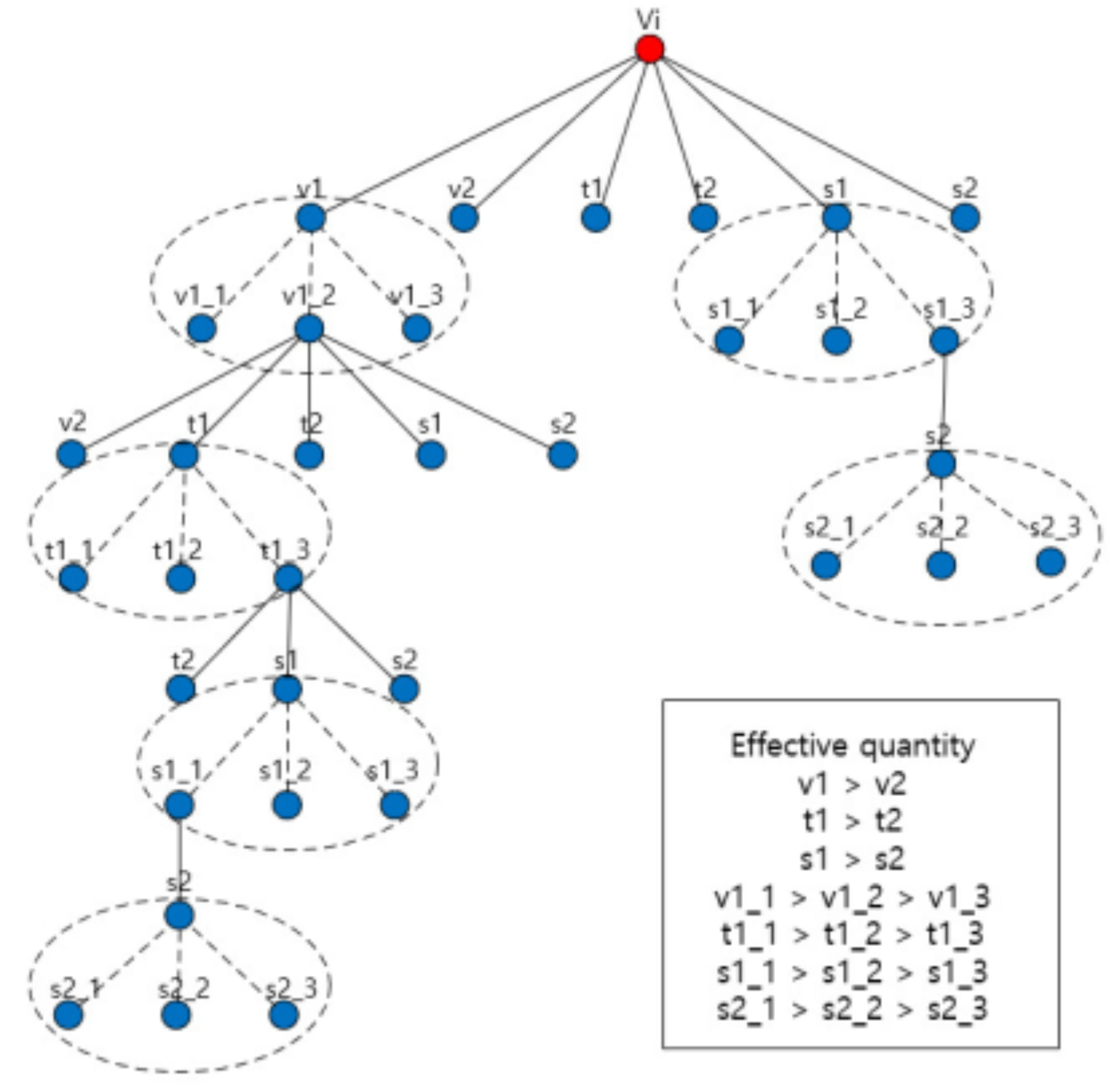
  • Step 1: Regarding a bus with abnormal bus voltage, a v1 node that has the largest effect quantity (sensitivity value control quantity) is selected by the system. Then, the system expands the v1 node as a three quantized effect quantity. Using the three quantized effect quantity, the system calculates the liner prediction and weighted evaluation function of all bus voltages. The evaluation function quantities of expanded nodes are 11, 9, and 10, as seen Figure 4. The system selects the v1_2 node with the smallest evaluation function value and progresses to select a compensation device in step 2.
  • Step 2: The system performs a liner prediction by using the effect quantity of v2. As a result, the system selects transformer tap t1 because abnormal bus voltage occurred in the normal bus. Then, through a process similar to that of v1, the system selects the t1_3 node with the smallest evaluation function quantity. Finally, if the abnormal bus voltage is dissolved, the system selects a compensation device in step 3. Conversely, if the abnormal bus voltage is solved, the system finishes the search process.

2.5. Overall Inference Process

As mentioned above, if abnormal voltages occur in a power system, then the expert system generates a search space using a sensitivity matrix. First, the most effective control equipment for the worst bus is selected. Then, the situation using the power flow is evaluated to confirm the effect. If the voltage regulation is confirmed, then it is checked whether there is an abnormal voltage in the other buses. If abnormal voltages are not detected, then the control result file is outputted. Figure 3 shows the conceptual flowchart of the overall inference process of the expert system.

3. Case Study

3.1. Structure of Korea’s Power System

As shown in Figure 6, approximately 40% of the total load in Korea is concentrated in metropolitan areas, and most of the generators are located far from the load-demand areas. Therefore, a large amount of power is transmitted from non-metropolitan to metropolitan areas. Moreover, a large amount of reactive power loss occurs, which may lead to voltage instability due to the lack of reactive power support in metropolitan areas. Therefore, the need for voltage control is increasingly growing. Most power plants in Korea are located in the southwest and southeast regions, whereas most loads are concentrated in the northern metropolitan areas. Figure 4 shows the structure of the transmission networks in Korea’s power system.

3.2. Case Study

In Korea, the standard bus voltage is 0.95–1.05 (p.u.) for 765 and 345 kV high-voltage transmission systems, which is similar to that in most countries. These limits can be changed by inputting data for general-purpose applications. If it is out of this range, then the voltage should be adjusted, as shown in Table 1. The generator quantization value is set to 5 in this case study, so the generator voltage can be changed by 0.1 (p.u.). As mentioned before, because generators have a faster response than other devices, the proposed system first selects generators.
This case study was performed for the entire Korean power system using practical PSS/E data provided by Korea Electric Power Corporation.
The next priority is to use shunt equipment. The transformer tap is used as the last rank, as transformers are usually internally regulated using the OLTC.
The case study performed N-1 contingency on the 765 kV transmission line, as shown in Figure 4. The transmission line where the fault occurred is the Shin Gapyeong–Shin Taebaek transmission line. Figure 5 shows three voltage profiles: pre-fault steady state, after fault without voltage control, and after fault with voltage control. In this figure, the x-axis represents the bus number. It is necessary to display each of the three states as a bar graph, but they are marked by dotted and solid lines instead of bars to increase the visibility of the bus voltage distribution.
As shown in Figure 6, abnormal under-voltages occurred at several buses after the fault in metropolitan areas. Then, all under-voltages were resolved by the control system. Table 2 shows the bus voltages after fault without control and after control.
Table 3 shows the control output of the proposed expert system. In this table, for example, V_21822 × 1 represents the generator identification tag. In this case, the under-voltage problem was solved by adjusting the voltage of nine generators.
Figure 6 shows the entire bus voltages in Korea’s power system.

3.3. Error Analysis

As the proposed system utilizes linear sensitivity data, we performed the comparative error analysis using the PSS/E program, which is a typical nonlinear simulation program in this field. As a result, the % errors are within 1%, as shown in Table 4. All other case studies showed a similar performance.

4. Conclusions

In this paper, a general-purpose intelligent voltage control system for bulk power systems was proposed. The proposed system consists of a numerical analysis module and a main expert system. The derivation of the sensitivity matrix and state-space generation, along with the searching strategy, was discussed first. Additionally, an effective performance index was proposed. Furthermore, as the sensitivity is the linearized value, a comparative study was performed to identify the prediction errors using the PSS/E simulation program. Based on our results, we have confirmed that the sensitivity errors are within 1% through various case studies.
As a result, the proposed system showed a promising performance for practical applications, and the pure processing time, except for the communication delay and SCADA scanning time delay, which depend on the year of manufacture and communication environment of the country, was found to be within one second for most cases using a personal computer system. The error due to linearization was confirmed to be within 1%. Moreover, the proposed structure strongly implies further extensive application to reactive power planning of bulk power systems.

Author Contributions

Conceptualization, H.L. and W.Y.; methodology, H.L.; validation, H.K. and J.K.; formal analysis, H.L.; investigation, H.L.; writing—original draft preparation, H.L.; writing—review and editing, J.O.; project administration, H.L.; funding acquisition, H.L. All authors have read and agreed to the published version of the manuscript.

Funding

This work was supported by the National Research Foundation of Korea (NRF) grant funded by the Korean government (MSIT) (No. 2020R1F1A1076667) and the Korea Institute of Energy Technology Evaluation and Planning (KETEP) and the Ministry of Trade, Industry & Energy (MOTIE) of the Republic of Korea (No. 20174010201620). The present research was also conducted under the Research Grant of Kwangwoon University in 2019.

Institutional Review Board Statement

Not applicable.

Informed Consent Statement

Not applicable.

Data Availability Statement

Not applicable.

Conflicts of Interest

The authors declare no conflict of interest.

References

  1. Jin, L.; Kumar, R.; Elia, N. Model predictive control-based real-time power system protection schemes. IEEE Trans. Power Syst. 2009, 25, 988–998. [Google Scholar] [CrossRef]
  2. Negenborn, R.; Beccuti, A.; Demiray, T.; Leirens, S.; Damm, G.; De Schutter, B.; Morari, M. Supervisory hybrid model predictive control for voltage stability of power networks. In Proceedings of the 2007 American Control Conference, New York, NY, USA, 9–13 July 2007; pp. 5444–5449. [Google Scholar] [CrossRef] [Green Version]
  3. Paul, J.P.; Leost, J.Y.; Tesseron, J.M. Survey of the secondary voltage control in France: Present realization and investigations. IEEE Trans. Power Syst. 1987, 2, 505–511. [Google Scholar] [CrossRef]
  4. Lefebvre, H.; Fragnier, D.; Boussion, J.; Mallet, P.; Bulot, M. Secondary coordinated voltage control system: Feedback of EDF. In Proceedings of the 2000 Power Engineering Society Summer Meeting, Seattle, WA, USA, 16–20 July 2002. [Google Scholar] [CrossRef]
  5. Corsi, S.; Pozzi, M.; Sabelli, C.; Serrani, A. The coordinated automatic voltage control of the Italian transmission grid—Part I: Reasons of the choice and overview of the consolidated hierarchical system. IEEE Trans. Power Syst. 2004, 19, 1723–1732. [Google Scholar] [CrossRef]
  6. Frias, P.; Gomez, T.; Soler, D. Voltage control and reactive power support in the Spanish transmission network. In Proceedings of the MELECON 2006—2006 IEEE Mediterranean Electrotechnical Conference, Malaga, Spain, 16–19 May 2006. [Google Scholar] [CrossRef]
  7. Cheng, S.; Malik, O.; Hope, G. An expert system for voltage and reactive power control of a power system. IEEE Trans. Power Syst. 1988, 3, 1449–1455. [Google Scholar] [CrossRef]
  8. Sancha, J.L.; Fernandez, J.L.; Martinez, F.; Salle, C. Spanish practices in reactive power management and voltage control. In Proceedings of the IEEE Colloquium on International Practices in Reactive Power Control IET, London, UK, 7 April 1993. [Google Scholar]
  9. Gómez, E.; Ramos, M.J.L.; Macias, R.J.L.; Salinas, C.Y. Sensitivity-based reactive power control for voltage profile improvement. IEEE Trans. Power Syst. 1993, 8, 937–945. [Google Scholar] [CrossRef]
  10. Ramos, J.L.M.; Exposito, A.; Cerezo, J.; Ruiz, E.; Salinas, F. A hybrid tool to assist the operator in reactive power/voltage control and optimization. IEEE Trans. Power Syst. 1995, 10, 760–768. [Google Scholar] [CrossRef]
  11. Belhadj, C.; Mohamedi, R.; Lefebvre, S.; Do, X.-D. An integrated power system global controller using expert system. In Proceedings of the 1996 Canadian Conference on Electrical and Computer Engineering, Calgary, AB, Canada, 26–29 May 1996; pp. 446–449. [Google Scholar]
  12. Le, T.L.; Negnevitsky, M.; Piekutowski, M. Network equivalents and expert system application for voltage and VAR control in large-scale power systems. IEEE Trans. Power Syst. 1997, 12, 1440–1445. [Google Scholar] [CrossRef]
  13. Seo, S.-S.; Choi, Y.-H.; Kang, S.-G.; Lee, B.-J.; Shin, J.-H.; Kim, T.-K. Hybrid control system for managing voltage and reactive power in the JEJU power system. J. Electr. Eng. Technol. 2009, 4, 429–437. [Google Scholar] [CrossRef]
  14. Choi, Y.-H.; Cho, Y.-S. Multiple-point voltage control to minimize interaction effects in power systems. Energies 2019, 12, 274. [Google Scholar] [CrossRef] [Green Version]
  15. Lee, H.J.; Yu, W.K.; Lim, C.H.; Lee, E.J.; Kim, G.D.; Kim, T.K.; Shin, J.H.; Nam, S.C.; Kang, Y.C. A study on the optimal search method of the hybrid intelligent voltage/reactive power control system. In Proceedings of the 2009 Transmission & Distribution Conference & Exposition: Asia and Pacific, Seoul, Korea, 26–30 October; 2009; pp. 1–4. [Google Scholar] [CrossRef]
  16. Lee, H.; Yu, W.; Wang, I.; Kang, H.; Shin, J. A study on the intelligent voltage control system. Trans. Korean Inst. Electr. Eng. 2012, 61, 944–949. [Google Scholar] [CrossRef] [Green Version]
  17. Yu, W.; Lee, H.; Kim, C.; Park, J.; Lee, K. A study on the Korea mainland power system application of intelligent voltage control system. In Proceedings of the International Smart Grid Conference, Gwangju, Korea, 12–14 October 2015. [Google Scholar]
  18. Lee, H.; Yu, W.; Oh, J. On the sensitivity matrix for reactive power control devices. Trans. Korean Inst. Electr. Eng. 2021, 70. submitted. [Google Scholar]
Figure 1. Structure of the proposed intelligent voltage control system.
Applsci 11 09233 g001
Figure 2. State-space model of voltage control.
Applsci 11 09233 g002
Figure 3. Flowchart of the inference process of the expert system.
Applsci 11 09233 g003
Figure 4. Structure of Korea’s power system.
Applsci 11 09233 g004
Figure 5. Three voltage profiles: pre-fault steady state, after fault state, and after fault with voltage control state.
Applsci 11 09233 g005
Figure 6. Voltage profile of all buses in the Korean power system.
Applsci 11 09233 g006
Table 1. Operation conditions for voltage control.
Upper Limit (p.u.)Lower Limit (p.u.)
Regulation voltage1.050.95
Generator terminal voltage range1.050.95
Generator voltage quantization5
Control equipment priorityGenerator voltage > Shunt capacitor/reactor > Tap
Table 2. Bus voltages of the pre-fault steady state, after fault state, and after fault with control.
Bus NumberSteady StateAfter FaultAfter Control
10200.98990.93560.9616
15250.99420.94910.9781
15450.98500.94040.9697
15650.98650.94260.9724
15750.98280.94060.9704
15850.98360.94090.9711
15900.97910.93420.9641
15950.98290.94380.9730
16300.99360.94850.9775
17201.00060.94840.9771
17400.99850.94610.9750
17460.99760.94510.9741
17700.99760.94350.9734
17860.99770.94360.9735
17900.99750.94340.9732
19850.99830.94580.9747
Table 3. Control output of the expert system.
Event NumberEquipment NumberControl Action (p.u.)
1V_21822X11.05
2V_21925X11.05
3V_25441X11.05
4V_25152X11.05
5V_25151X11.05
6V_25154X11.05
7V_25153X11.05
8V_23252X11.05
9V_25152X10.95
Table 4. Results of the linear prediction error.
Bus NumberPSS/ELinear Prediction %   E r r o r
10200.96160.96360.2080
15250.97810.98460.6688
15450.96970.97690.7497
15650.97240.98040.8308
15750.97040.97830.8232
15850.97110.97980.8987
15900.96410.97210.8322
15950.97300.98000.7295
16300.97750.98400.6706
17200.97710.98260.5696
17400.97500.98050.5658
17460.97410.97960.5682
17700.97340.97990.6746
17860.97350.98000.6725
17900.97320.97980.6854
19850.97470.98020.5734
Publisher’s Note: MDPI stays neutral with regard to jurisdictional claims in published maps and institutional affiliations.

