Development of an Analytical Model to Determine the Heat Fluxes to a Structural Element Due to a Travelling Fire
Abstract
:1. Introduction
2. Development of a New Analytical Model Based on the Virtual Solid Flame Concept
2.1. Basic Assumptions
- The plan view of the compartment has a rectangular shape;
- The floor and the ceiling of the compartment are flat and horizontal;
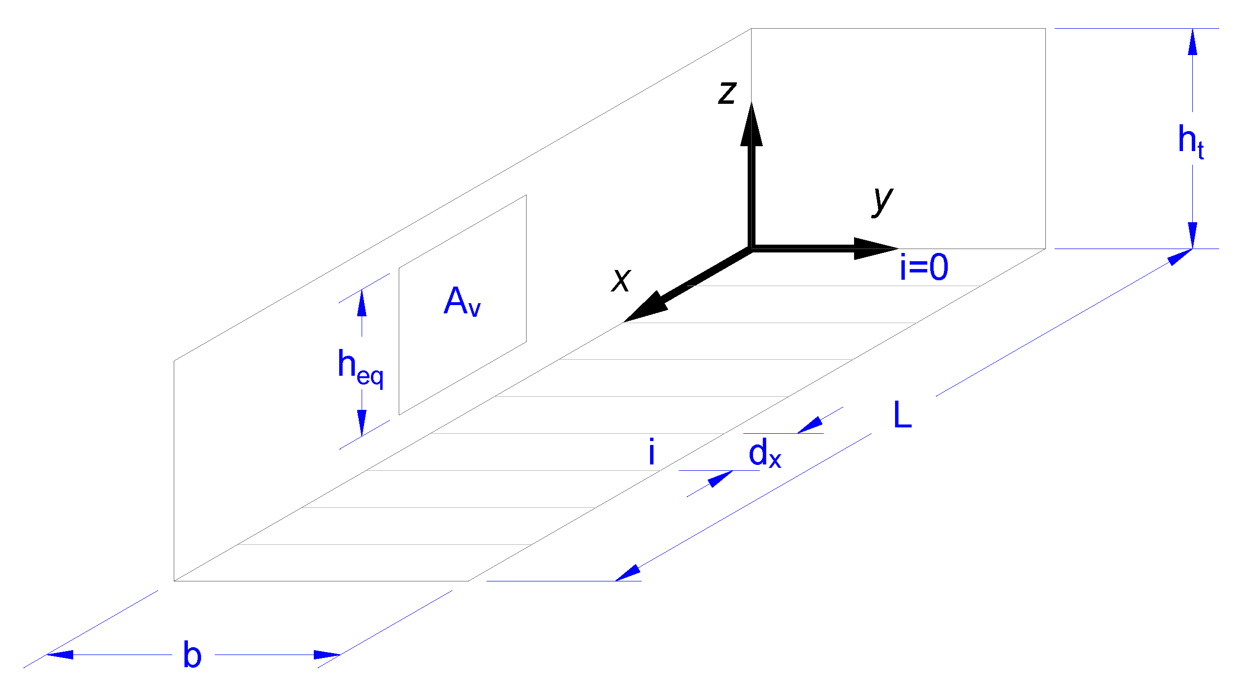
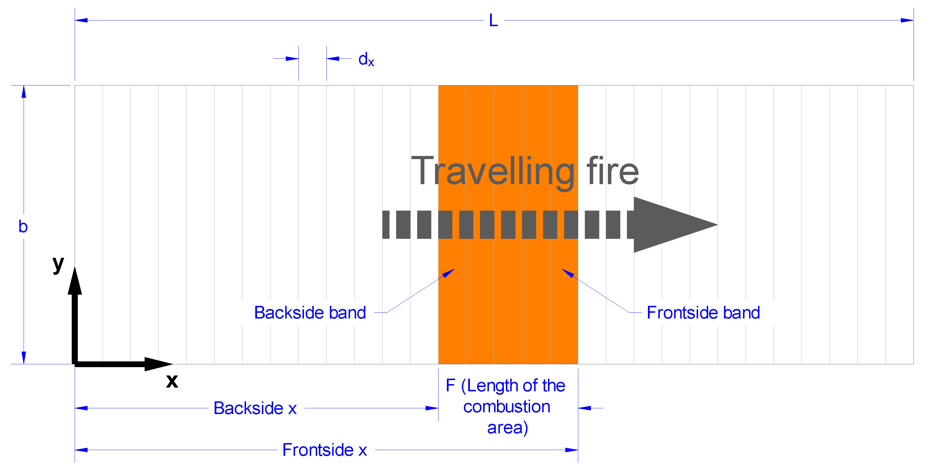
- The plan view is divided into bands of equal width parallel to the defined plan dimension b (see Figure 1);
- The fire load is uniformly distributed in the compartment, covering the whole floor area;
- The fire starts in the band close to one of the façades and spreads from band to band;
- The fire is represented as a rectangular volume the basis of which is given by the burning bands;
- The spread rate is given as an input and remains constant during the duration of the fire;
- The rate of heat release in all burning bands is reduced if the fire is ventilation controlled;
- The openings defined in the method are considered as fully open.
2.2. Evaluation of the Fire Geometry and Its Position in the Compartment
- dx = width of each band;
- ndx = quantity of bands;
- The index i is used to denote the band number. Band (1) extends from x = 0 to x = dx, band (i) extends from x = (i − 1).dx to x = i.dx, etc.;
- At time t = 0, fire starts in band (1) only and will thus spread towards increasing values of x, i.e., to band (2), and then band (3), etc.
- The following inputs have to be given to describe the problem:
- Width b, length L, and floor to ceiling distance ht of the compartment [m];
- Width of the bands dx [m], the total number of bands ndx is therefore evaluated by rounding up the ratio L/dx, and dx is then re-evaluated as dx = L/ndx;
- The design value of the fire load density qf,d [MJ/m2];
- The rate of heat release density RHRf [kW/m2];
- The height of the fire load basis hbase (to allow for elevated combustible, the floor height being situated at 0 m height) [m];
- The fire spread rate v [mm/s];
- The combustion factor m (fixed to 0.8 in EN1991-1-2 [13]) [-];
- The effective heat of combustion of the fire load H [MJ/kg];
- The total area of vertical openings Av (as the openings are considered as fully open, this area should correspond to the area of broken or open windows and doors) [m2];
- The equivalent height of the openings heq [m];
- The time-step dt [s].
2.2.1. Position of the Fire
2.2.2. Power and Fire Load Density
2.2.3. Flame Length
2.3. Evaluation of the Flame Temperature and of the Heat Fluxes in the Compartment
2.3.1. Flame Temperature
2.3.2. Heat Fluxes
- Fr,f refers to the radiative heat flux emitted by the fire surface and received by the structural member;
- Fr,b refers to the radiative heat flux emitted by the surrounding background and received by the structural member;
- Fr,s refers to the radiative heat flux emitted by the structural member;
- Fc refers to the convective heat flux received by the structural member from its surrounding environment;
- Ftot refers to the total net heat flux at the surface of the structural member at a certain height.
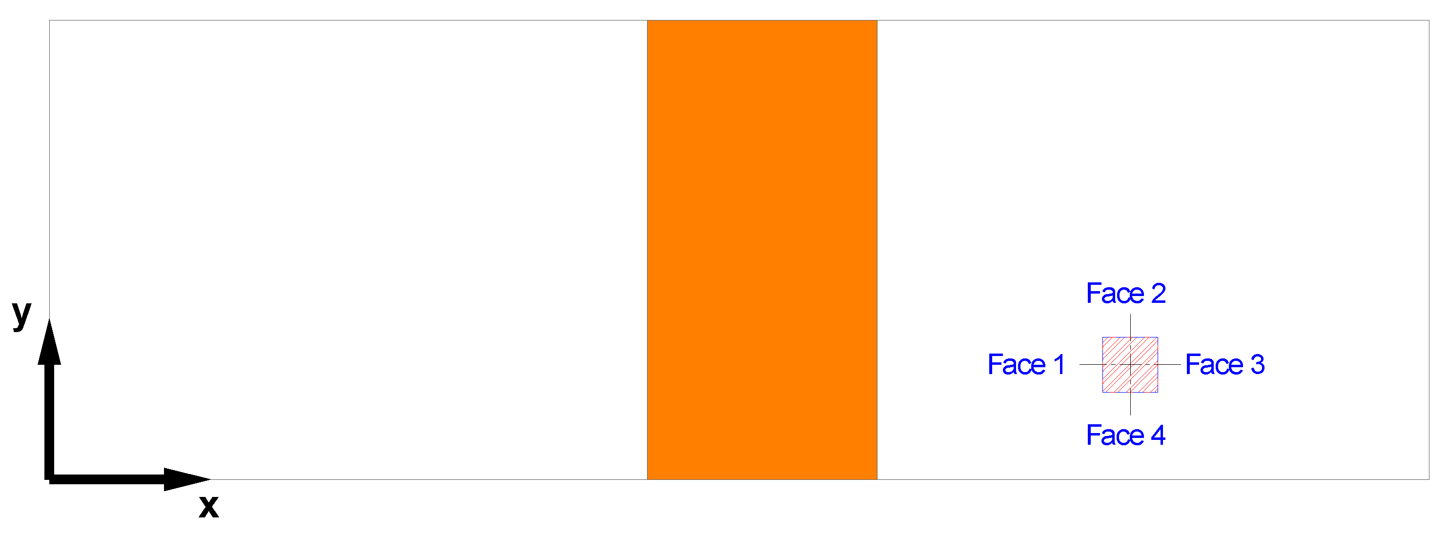
- dA1 refers to an infinitesimal area on the face l—located at the height of interest on the structural member—which receives the radiative heat flux;
- dA2 refers to an infinitesimal area on the surface of the solid flame which emits the radiative heat flux;
- TA2 is the local temperature of the flame at height zs [°C] (as detailed in previous sub-section);
- σ = 5.67 × 10⁻⁸ is the Stefan–Boltzmann constant [Wm−2K−4];
- εm (generally = 0.7) is the surface emissivity of the steel member [-];
- εf (generally assumed to be = 1) is the surface emissivity of the flame [-].
- y′ is a dimensionless parameter given by
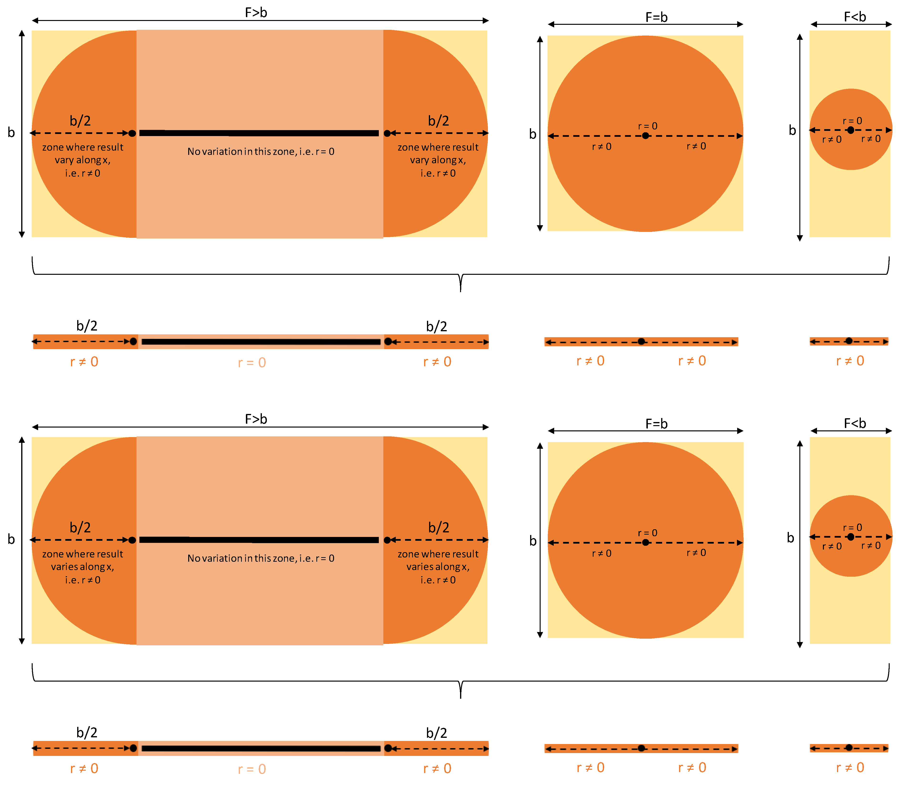
- r is the x-component of the horizontal distance (in m) between the equivalent vertical axis of the fire and the structural member axis, given by the Equation (20) (see Figure 2)
- ht−hbase is the distance, in m, between the fire source basis and the ceiling
- z′ is the vertical position of the virtual heat source, in m, given by
- Lh is the horizontal flame length, in m, given by
2.4. Evaluation of the Steel Temperature of a Structural Member Placed in the Compartment
- Am the surface area of the member per unit length [m2/m];
- V the volume of the member per unit length [m3/m];
- Am/V the section factor for unprotected steel members [m−1];
- (Am/V)b the box value of the section factor (box refers here to the rectangular envelope around the steel member) [m−1];
- ca the specific heat of steel [Jkg−1K−1] as given in EN1993-1-2 § 3.4.1.2 [22];
- Ftot the design value of the net heat flux per unit area [W/m2];
- Δt the time interval [s];
- ρa = 7850 kg/m3 the unit mass of steel.
3. Comparison of Steel Temperatures from the Model with Experimental Results
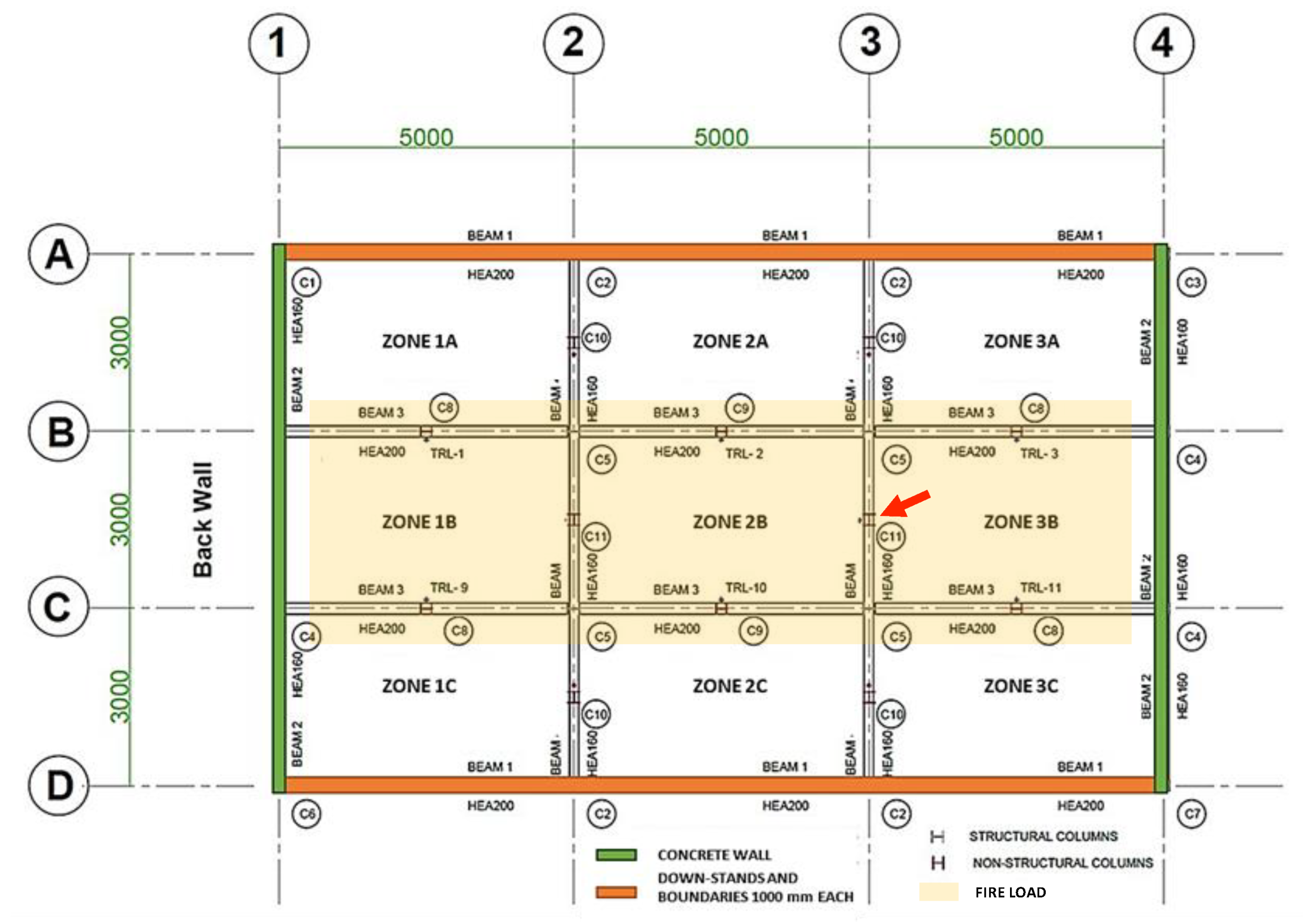
3.1. Experimental Travelling Fire Test in a Steel Building
3.2. Steel Temperatures in Central Columns
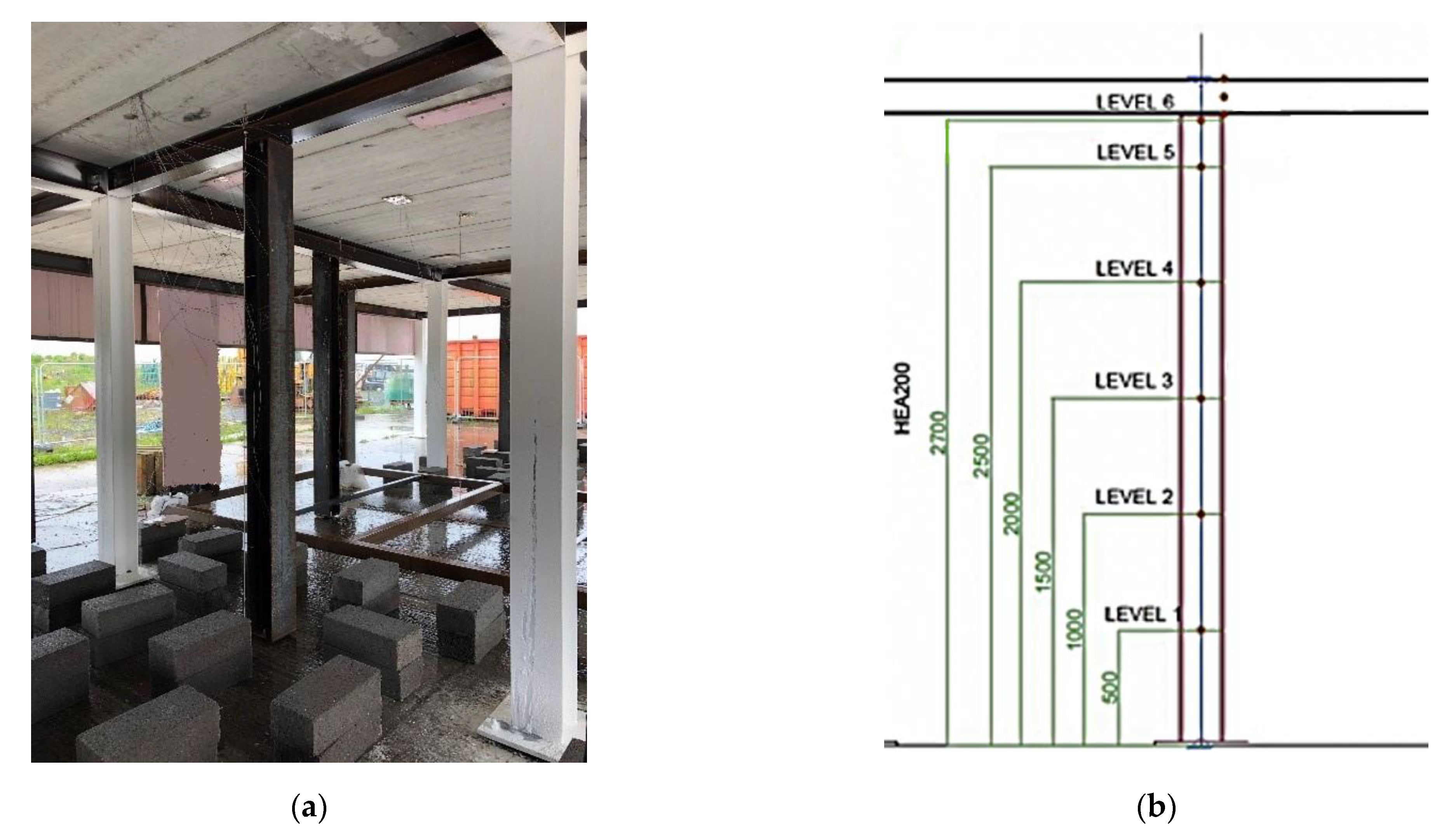
3.2.1. Experimental Measurements
3.2.2. Comparison of the Results
- The design fire load density qf,d = 511 MJ/m2;
- The height of the fire load basis hbase = 0.325 m;
- The net heat of combustion of the fire load H was estimated from a bomb calorimeter test (performed by the University of Edinburgh) as 16.8 MJ/kg;
- The total area of vertical openings Av = 30 m2;
- The equivalent height of the openings heq = 1 m.
- Other input parameters were taken from EN 1991-1-2:
- The combustion factor m = 0.8 (leading to an effective heat of combustion = 13.44 MJ/kg);
- The coefficient of convection heat transfer on the steel surface αc = 35 W/m2K;
- The flame emissivity εf = 1;
- The steel emissivity εm = 0.7;
- The time-steps dt = Δt = 5 sec.
- The rate of heat release density RHRf has been set to 400 kW/m2, an evaluation made from the mass loss test measurement;
- Several fire spread rates v were considered and the present comparison was achieved with 3.2 mm/s which is representative of the fire spread rate observed in the first half of the compartment;
- The width of each band was set as dx = 25 cm (nearly identical results are obtained with a band width of 50 cm);
- The thickness of the flame layers dz = 10 cm (no sensitivity analysis was carried out for this parameter).
4. Discussion and Application Field of the Model
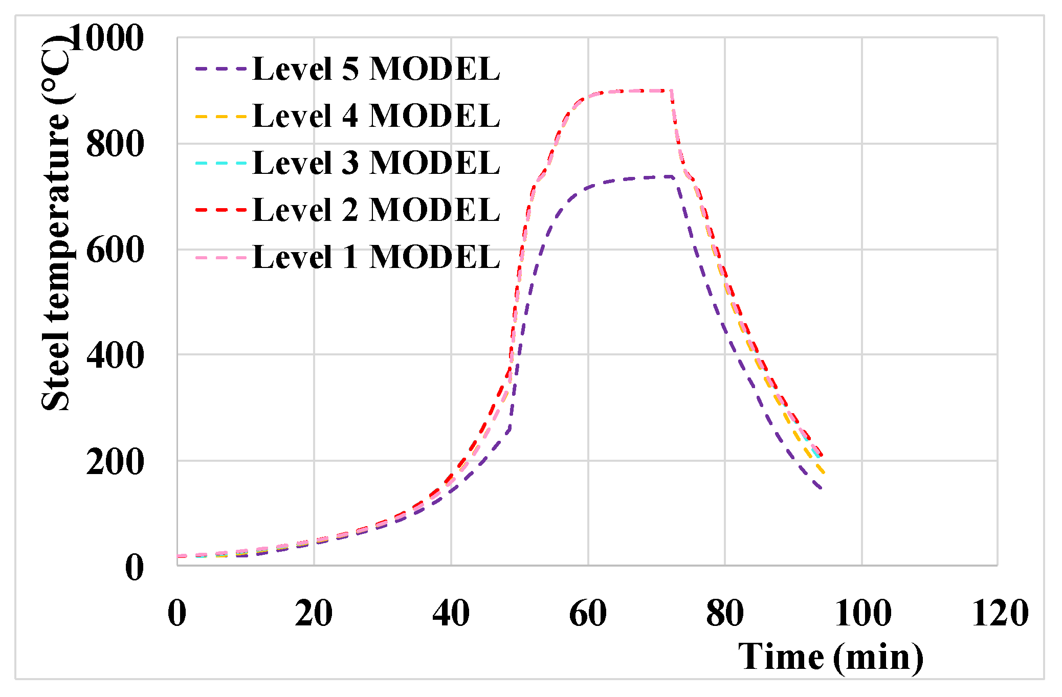
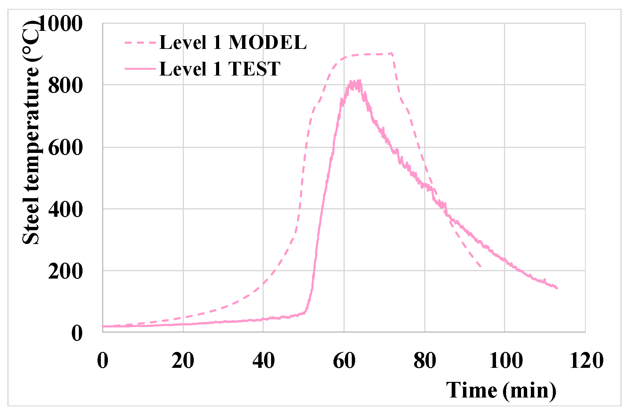
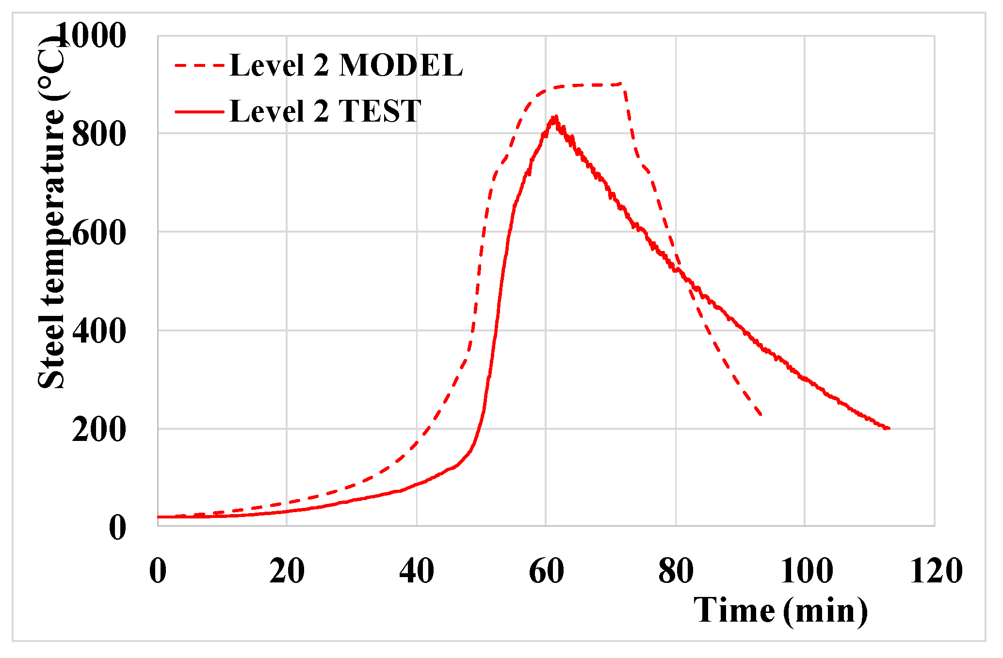
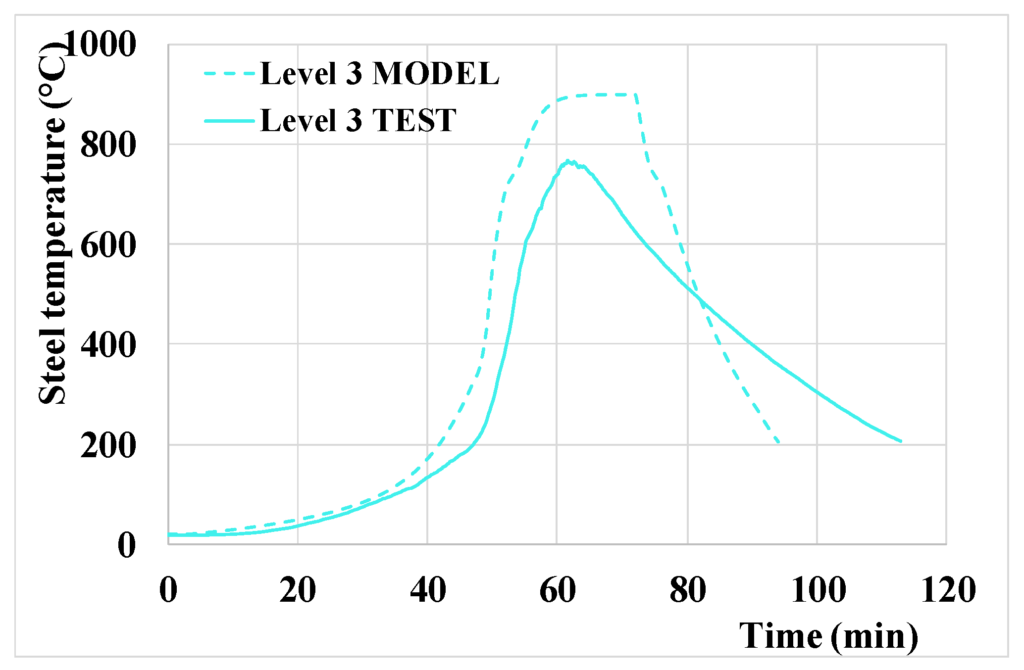
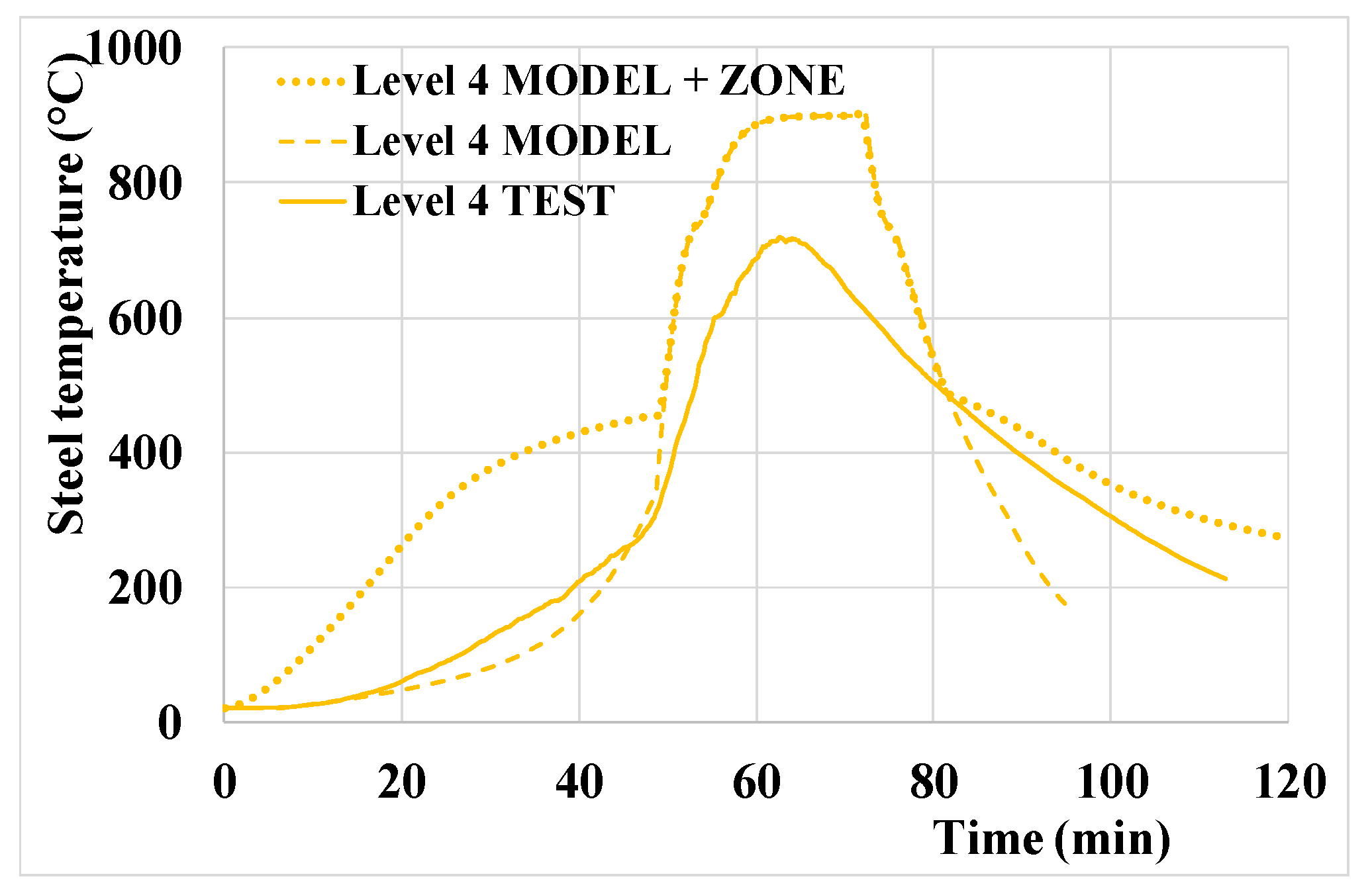
- The global profile versus time is well captured;
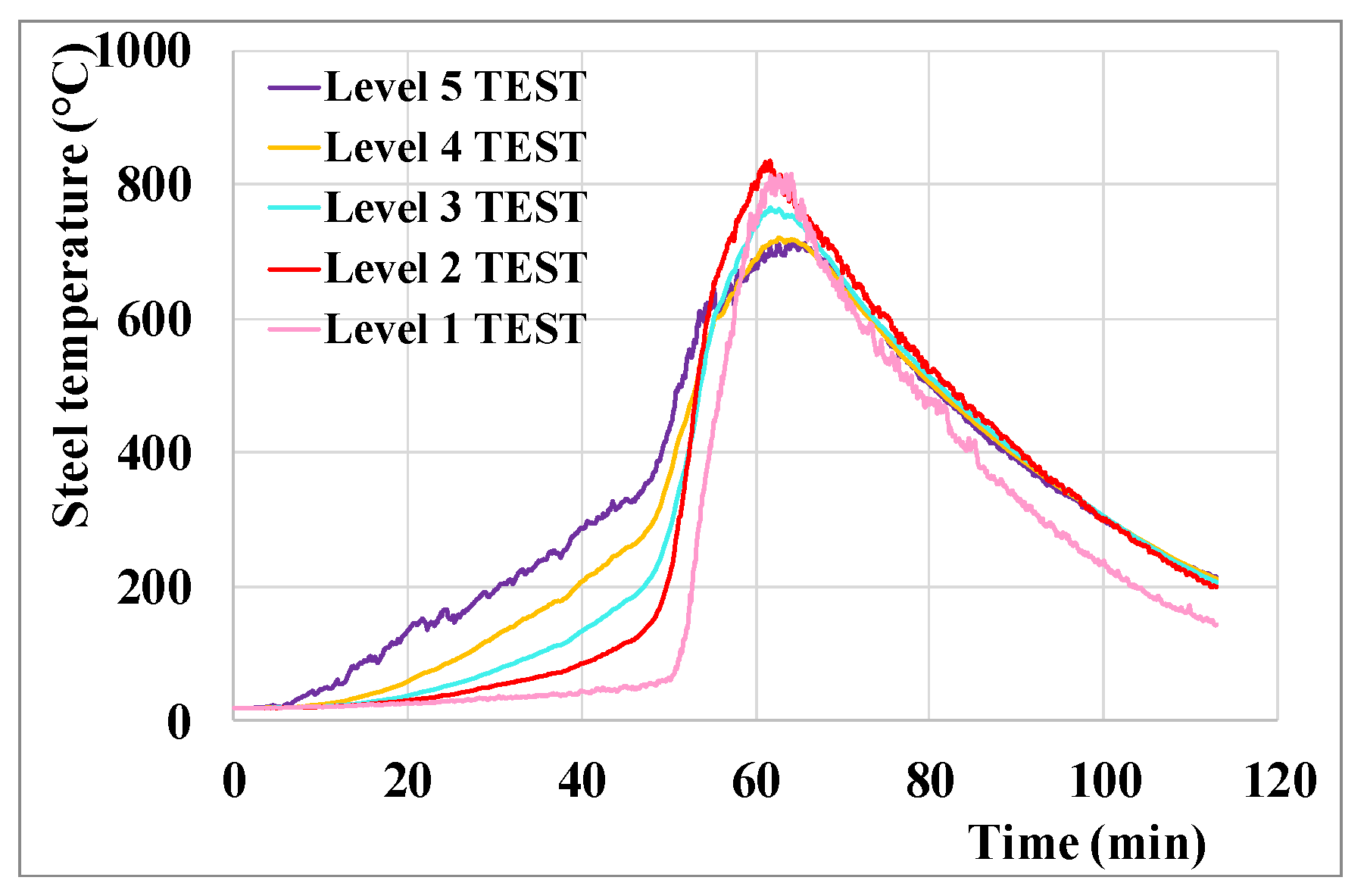
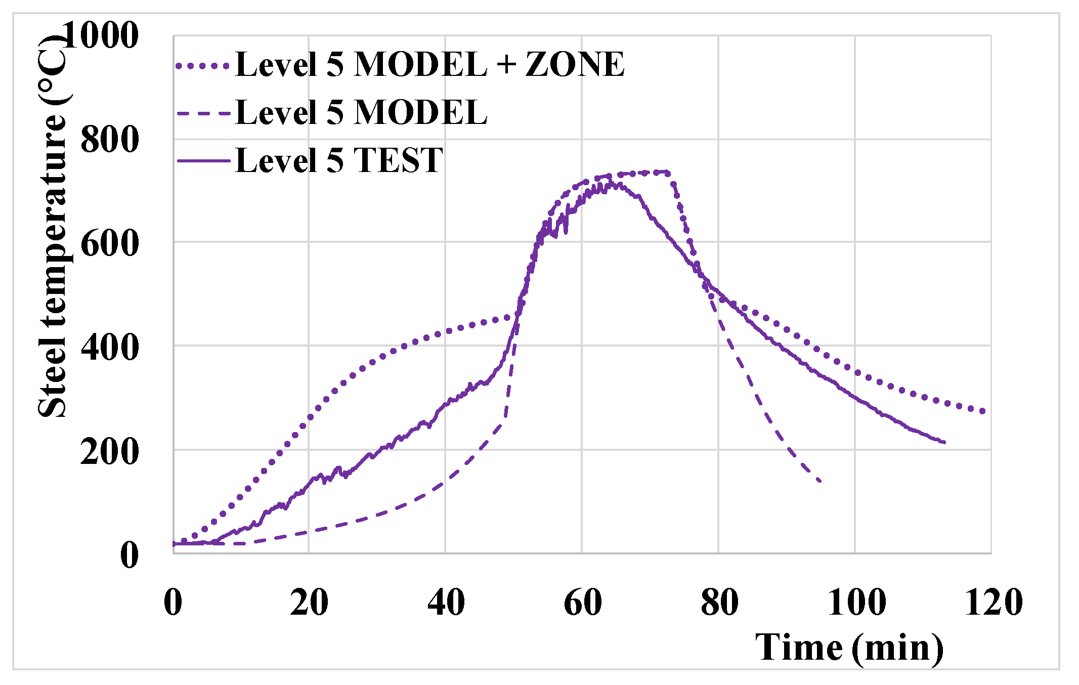
- The obtained steel temperatures are safe-sided for all levels. The peak temperatures are quite close to the ones measured during the test, except for mid-levels (3 and 4) where a non-negligible difference is found: for levels 1 and 2 the difference is around 90 °C (900 °C for the model versus 810 °C for the test). For levels 3 and 4 the difference is around (respectively) 150 and 190 °C (900 °C for the model versus, respectively, 750 and 710 °C for the test). For level 5, the peak temperature is similar, around 710 °C;
- The time during which the steel temperatures are high (i. e. above 500 °C—threshold arbitrarily chosen in a domain where the yield strength of steel has started to decrease) is slightly longer for the model than for test at levels 1, 2 and 3 (around 27 min for the test and 30 min for the model). However, for levels 4 and 5 a very good match is observed with 30 min for both the model and the test;
- However, for steel temperatures above 700 °C (temperature for which the yield strength of steel has significantly decreased) the difference is more important. With the model, steel temperatures are above 700 °C during 25 min for levels 1, 2, 3 and 4 and 15 min for level 5 while for the test this duration is approximately 10 min for levels 1 and 3, 12 min for level 2 and 5 min for levels 4 and 5;
- The developed model considers only the effect of the spreading localised fire, and needs to be coupled to a zone model for the upper levels to consider the hot gases which develop under the ceiling. For the highest level (level 5 which is located 40 cm below the ceiling), the application of the model only leads to unsafe results for the heating branch and to a good representation of the peak temperatures. The combination with a zone model allows to improve the representation of the fire; the peak temperatures are unchanged, but the heating branch is better captured with safe-sided results. For the level 4, which is located 90 cm below the ceiling, the application of the model only leads to slightly unsafe results for the heating branch and to significantly safe-sided results for the peak temperatures. The combination with a zone model leads to significantly safe-sided results for both the heating branch and the peak temperatures (which are unchanged);
- The descending branch is underestimated once steel temperatures goes below 400 °C. Such issue was also noticed through CFD numerical modelling (Charlier et al., 2021); this can be explained by the model’s inability to properly capture heat release from glowing embers, as well as the heat accumulated within the compartment boundaries.
5. Conclusions
Author Contributions
Funding
Institutional Review Board Statement
Informed Consent Statement
Data Availability Statement
Acknowledgments
Conflicts of Interest
References
- Horová, K. Modelling of Fire Spread in Structural Fire Engineering. Ph.D. Thesis, Czech Technical University in Prague, Prague, Czechia, 2015. [Google Scholar]
- Degler, J.; Eliasson, A.; Anderson, J.; Lange, D.; Rush, D. A-priori modelling of the Tisova fire test as input to the experimental work. In Proceedings of the 1st International Conference on Structural Safety under Fire & Blast, Glasgow, UK, 2–4 September 2015. [Google Scholar]
- Charlier, M.; Gamba, A.; Dai, X.; Welch, S.; Vassart, O.; Franssen, J.-M. CFD analyses used to evaluate the influence of compartment geometry on the possibility of development of a travelling fire. In Proceedings of the 10th International Conference on Structures in Fire, Ulster University, Belfast, UK, 6–8 June 2018; pp. 341–348. [Google Scholar]
- Charlier, M.; Glorieux, A.; Dai, X.; Alam, N.; Welch, S.; Anderson, J.; Vassart, O.; Nadjai, A. Travelling fire experiments in steel-framed structure: Numerical investigations with CFD and FEM. J. Struct. Fire Eng. 2021, 12, 309–327. [Google Scholar] [CrossRef]
- Dai, X.; Welch, S.; Rush, D.; Charlier, M.; Anderson, J. Characterising natural fires in large compartments—Revisiting an early travelling fire test (BST/FRS1993) with CFD. In Proceedings of the 15th International Interflam Conference, London, UK, 1–3 July 2019. [Google Scholar]
- Stern-Gottfried, J.; Rein, G. Travelling fires for structural design-Part II: Design methodology. Fire Saf. J. 2012, 54, 96–112. [Google Scholar] [CrossRef] [Green Version]
- Rackauskaite, E.; Hamel, C.; Law, A.; Rein, G. Improved Formulation of Travelling Fires and Application to Concrete and Steel Structures. Struct. 2015, 3, 250–260. [Google Scholar] [CrossRef] [Green Version]
- Vassart, O.; Hanus, F.; Brasseur, M.; Obiala, R.; Franssen, J.-M.; Scifo, A.; Zhao, B.; Thauvoye, C.; Nadjai, A.; Sanghoon, H. LOCAFI: Temperature Assessment of a Vertical Steel Member Subjected to Localised Fire—Final Report, Research Fund for Coal and Steel; European Commission: Brussels, Belgium, 2016. [Google Scholar]
- Tondini, N.; Thauvoye, C.; Hanus, F.; Vassart, O. Development of an analytical model to predict the radiative heat flux to a vertical element due to a localised fire. Fire Saf. J. 2019, 105, 227–243. [Google Scholar] [CrossRef]
- Dai, X.; Welch, S.; Vassart, O.; Cábová, K.; Jiang, L.; Maclean, J.; Clifton, G.C.; Usmani, A. An extended travelling fire method framework for performance-based structural design. Fire Mater. 2020, 44, 437–457. [Google Scholar] [CrossRef]
- Janssens, M.L. An Introduction to Mathematical Fire Modeling, 2nd ed.; CRC Press: Lancaster, PA, USA, 2000. [Google Scholar]
- Kawagoe, K. Fire Behaviour in Rooms; Report of the Building Research Institute: Ibaraki-ken, Japan, 1958. [Google Scholar]
- CEN (European Committee for Standardization). EN1991-1-2: Eurocode 1: Actions on Structures—Part 1–2: General Actions—Actions on Structures Exposed to Fire; CEN: Brussels, Belgium, 2002. [Google Scholar]
- Zukoski, E.; Kubota, T.; Cetegen, B. Entrainment in fire plumes. Fire Saf. J. 1981, 3, 107–121. [Google Scholar] [CrossRef]
- Merci, B.; Beji, T. Fluid Mechanics Aspects of Fire and Smoke Dynamics in Enclosures; CRC Press: Boca Raton, FL, USA; Balkena: Amsterdam, The Netherlands, 2016. [Google Scholar]
- Heskestad, G. Luminous heights of turbulent diffusion flames. Fire Saf. J. 1983, 5, 103–108. [Google Scholar] [CrossRef]
- Heskestad, G. Engineering relations for fire plumes. Fire Saf. J. 1984, 7, 25–32. [Google Scholar] [CrossRef]
- SFPE Handbook of Fire Protection Engineering, 3rd ed.; NFPA: Quincy, MA, USA, 2002.
- Randaxhe, J.; Popa, N.; Tondini, N. Probabilistic fire demand model for steel pipe-racks exposed to localised fires. Eng. Struct. 2021, 226, 111310. [Google Scholar] [CrossRef]
- McCaffrey, B. The SFPE Handbook of Fire Protection Engineering, 2nd ed.; Society of Fire Protection Engineers and National Fire Protection Association: Quincy, MA, USA, 1995. [Google Scholar]
- Morton, B.R. Modeling of fire plumes. In Proceedings of the 10th International Symposium on Combustion; The Combustion Institute: Pittsburgh, PA, USA, 1965. [Google Scholar]
- CEN (European Committee for Standardization). EN1993-1-2: Eurocode 3: Design of Steel Structures—Part 1–2: General Rules—Structural Fire Design; CEN: Brussels, Belgium, 2005. [Google Scholar]
- Hasemi, Y.; Tokunaga, T. Flame Geometry Effects on the Buoyant Plumes from Turbulent Diffusion Flames. Fire Sci. Technol. 1984, 4, 15–26. [Google Scholar] [CrossRef] [Green Version]
- Pchelintsev, A.; Hasemi, Y.; Wakarnatsu, T.; Yokobayashi, Y.; Wakamatsu, T. Experimental and Numerical Study On The Behaviour of A Steel Beam Under Ceiling Exposed to A Localized Fire. Fire Saf. Sci. 1997, 5, 1153–1164. [Google Scholar] [CrossRef] [Green Version]
- Hasemi, Y.; Yokobayashi, Y.; Wakamatsu, T.; Ptchelintsev, A. Fire Safety of Building Components Exposed to a Localized Fire—Scope and Experiments on Ceiling/Beam System Exposed to a Localized Fire; Interscience Communications: Gosport, Hampshire, UK, 1995. [Google Scholar]
- Wakamatsu, T.; Hasemi, Y.; Yokobayashi, Y.; Ptchelintsev, A. Experimental Study on the Heating Mechanism of a Steel Beam under Ceiling exposed to a localized Fire. In Proceedings of the 7th Interflam Conference, Cambridge, UK, 26–28 March 1996; pp. 509–518. [Google Scholar]
- CEN (European Committee for Standardization). prEN 1991-1-2:2021 E: Eurocode 1: Actions on Structures—Part 1-2: General Actions—Actions on Structures Exposed to Fire; CEN: Brussels, Belgium, 2021. [Google Scholar]
- Alam, N.; Nadjai, A.; Charlier, M.; Vassart, O.; Welch, S.; Sjöström, J.; Dai, X. Large-Scale-Travelling-Fire-Tests with Open-Ventilation-Conditions and Their Effect on the Surrounding Steel-Structure—The-Second-Fire-Test. J. Constr. Steel Res. Under Review.
- Gamba, A.; Charlier, M.; Franssen, J.-M. Propagation tests with uniformly distributed cellulosic fire load. Fire Saf. J. 2020, 117, 103213. [Google Scholar] [CrossRef]
- Cadorin, J.-F.; Franssen, J.-M. A tool to design steel elements submitted to compartment fires—OZone V2. Part 1: Pre- and post-flashover compartment fire model. Fire Saf. J. 2003, 38, 395–427. [Google Scholar] [CrossRef]
- Charlier, M.; Franssen, J.-M.; Temple, A.; Welch, S.; Nadjai, A. Characterization of Travelling Fires in Large Compartments (TRAFIR); European Commission: Brussels, Belgium, 2021; Technical steel research, Draft Final Report (under review). [Google Scholar]
- Hidalgo, J.P.; Cowlard, A.; Abecassis-Empis, C.; Maluk, C.; Majdalani, A.; Kahrmann, S.; Hilditch, R.; Krajcovic, M.; Torero, J. An experimental study of full-scale open floor plan enclosure fires. Fire Saf. J. 2017, 89, 22–40. [Google Scholar] [CrossRef]
- Gupta, V.; Osorio, A.F.; Torero, J.L.; Hidalgo, J.P. Mechanisms of flame spread and burnout in large enclosure fires. Proc. Combust. Inst. 2021, 38, 4525–4533. [Google Scholar] [CrossRef]



| Scenario 1—The Flame does not Impact the Ceiling of the Compartment | ||||||
|---|---|---|---|---|---|---|
| Heat Flux Component | Zone 1 | Zone 2 | Zone 3 | Zone 4 | Zone 5 | Zone 6 |
| Fr,f | ✔ | ✔ | ✔ | ✔ | ||
| Fr,b,ambient | ✔ | ✔ | ✔ | ✔ | ||
| Fr,b,Heskestad | ✔ | ✔ | ||||
| Fr,b,Hasemi | ||||||
| Fr,s | ✔ | ✔ | ✔ | ✔ | ✔ | ✔ |
| Fc | ✔ | ✔ | ✔ | ✔ | ✔ | ✔ |
| Scenario 2—The Flame Impacts the Ceiling of the Compartment | ||||||
|---|---|---|---|---|---|---|
| Heat Flux Component | Zone 1 | Zone 2 | Zone 3 | Zone 4 | Zone 5 | Zone 6 |
| Fr,f | ✔ | ✔ | ||||
| Fr,b,ambient | ✔ | ✔ | ||||
| Fr,b,Heskestad | ✔ | ✔ * | ||||
| Fr,b,Hasemi | ✔ | ✔ * | ✔ | |||
| Fr,s | ✔ | ✔ | ✔ | ✔ | ✔ | ✔ |
| Fc | ✔ | ✔ | ✔ | ✔ | ✔ | ✔ |
Publisher’s Note: MDPI stays neutral with regard to jurisdictional claims in published maps and institutional affiliations. |
© 2021 by the authors. Licensee MDPI, Basel, Switzerland. This article is an open access article distributed under the terms and conditions of the Creative Commons Attribution (CC BY) license (https://creativecommons.org/licenses/by/4.0/).
Share and Cite
Charlier, M.; Franssen, J.-M.; Dumont, F.; Nadjai, A.; Vassart, O. Development of an Analytical Model to Determine the Heat Fluxes to a Structural Element Due to a Travelling Fire. Appl. Sci. 2021, 11, 9263. https://doi.org/10.3390/app11199263
Charlier M, Franssen J-M, Dumont F, Nadjai A, Vassart O. Development of an Analytical Model to Determine the Heat Fluxes to a Structural Element Due to a Travelling Fire. Applied Sciences. 2021; 11(19):9263. https://doi.org/10.3390/app11199263
Chicago/Turabian StyleCharlier, Marion, Jean-Marc Franssen, Fabien Dumont, Ali Nadjai, and Olivier Vassart. 2021. "Development of an Analytical Model to Determine the Heat Fluxes to a Structural Element Due to a Travelling Fire" Applied Sciences 11, no. 19: 9263. https://doi.org/10.3390/app11199263
APA StyleCharlier, M., Franssen, J.-M., Dumont, F., Nadjai, A., & Vassart, O. (2021). Development of an Analytical Model to Determine the Heat Fluxes to a Structural Element Due to a Travelling Fire. Applied Sciences, 11(19), 9263. https://doi.org/10.3390/app11199263


