In this section we present the experimental devices from our setup and discuss the methodology. We also present the software implementation architecture.
2.1. Experimental Devices and Methodology for Audio Key Extraction
In the experiments we used several smartphones with different versions of Android, starting from older devices like the Nexus 7 to newer mid-range devices such as the Motorola E6 Plus. This allowed us to determine whether differences between Android APIs and device characteristics can create problems during the acoustic domain pairing. Also, as representative for our main use case, i.e., the in-vehicle scenario, we used an off-the-shelf PX5 Android infotainment unit. A summary of the used devices and some of their specifications are available in
Table 2. On the left side of
Figure 2 we depict the smartphones used in our experiments and in the right side of the figure we depict the devices placed on the vehicle dashboard.
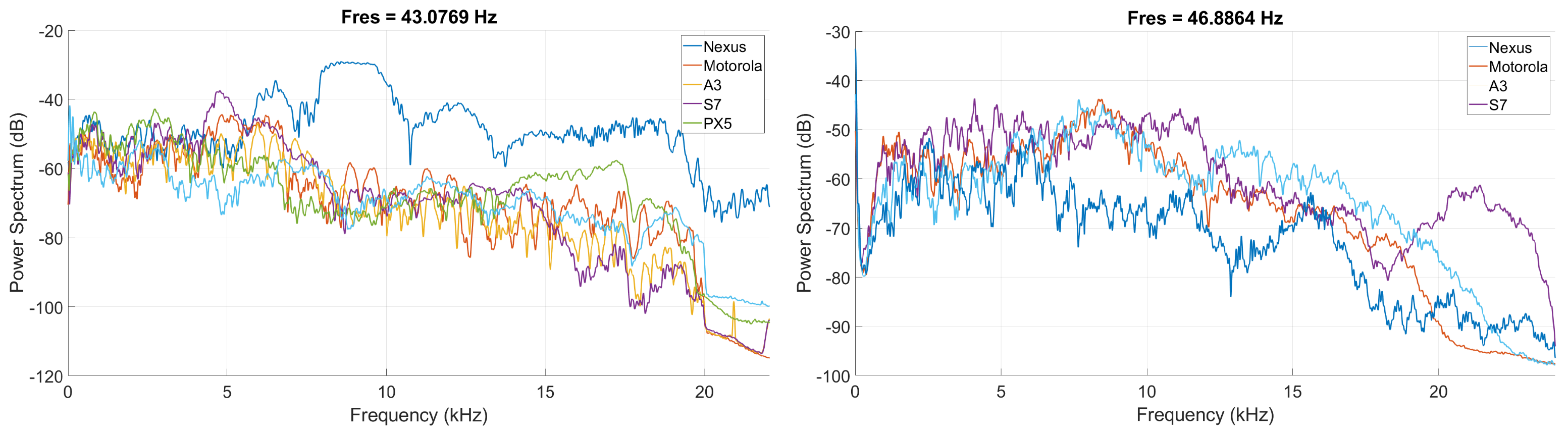
To depict the audio acquisition capabilities of the devices, on the left side of
Figure 3 we show the power spectrum from the recordings by each device during a linear sweep signal between 20 Hz and 22 kHz that is played by a high-end HiFi system. In this figure, it can be seen that the frequency response of the microphone of the Nexus smartphone is more distinct than for the rest of the devices. On the right side of
Figure 3, we depict the power spectrum of a linear sweep signal between 20 Hz and 22 kHz when played by the devices from our experiments and recorded by a calibrated UMIK-1 microphone. In this figure the frequency response of the speaker of the Nexus and Samsung A3 smartphone is more distinct than the Samsung S7 and Motorola E6 speaker frequency response. For these measurements the distance between the speaker and the microphone was 100 cm.
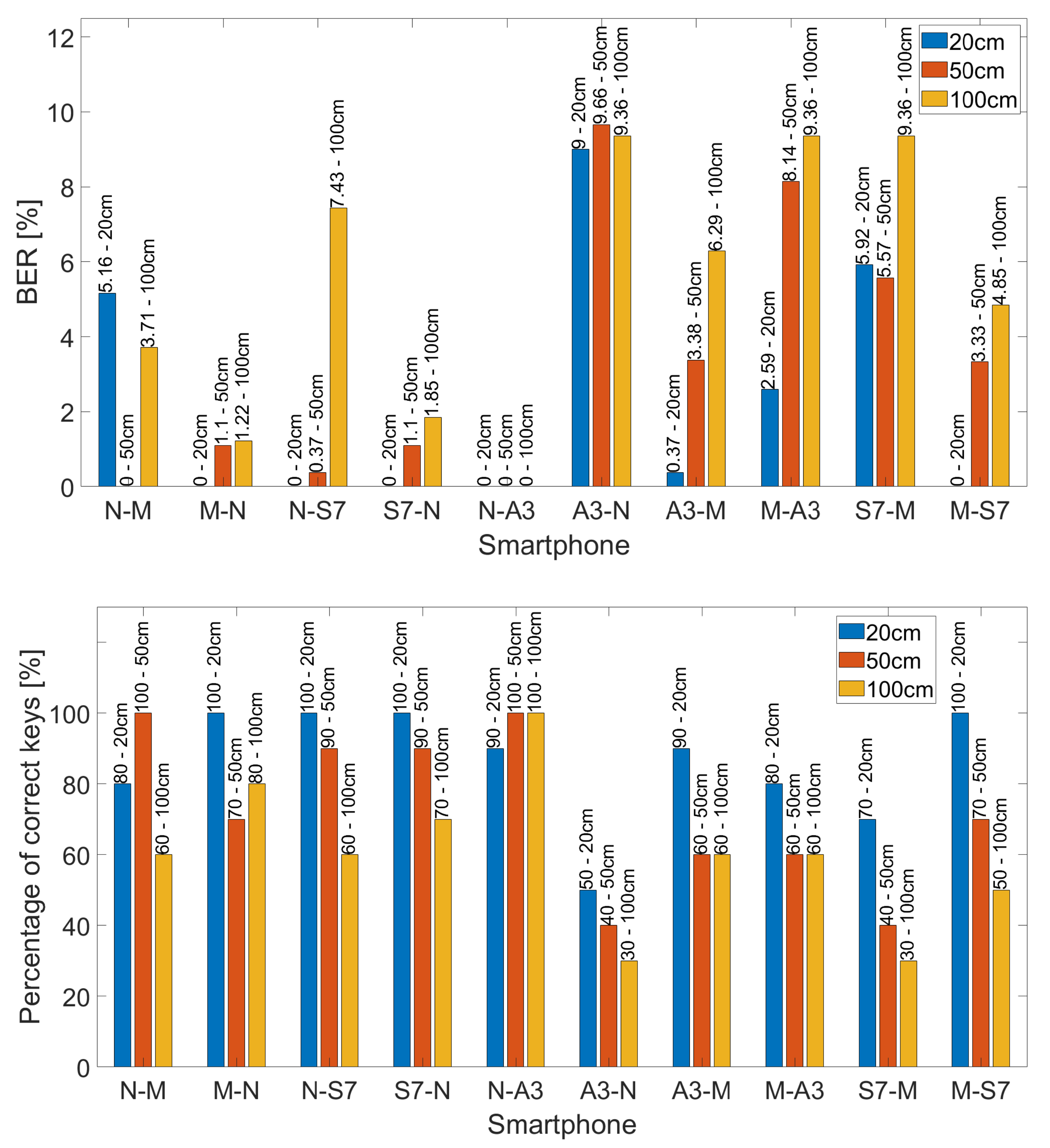
The distinct frequency responses from the speakers and microphones of our devices explain some of the disparities from the experiments that we present later. For example, for the experiments performed indoors, at 50 cm between devices, when the Nexus was used as emitter and the Motorola E6 as receiver, 100% of the keys were correctly received. However, when the emitter and receiver roles are shifted, i.e., Motorola E6 is the emitter and Nexus the receiver, only 70% of the keys are correct.
2.2. Software Implementation
Since our experiments are exclusively concerned with Android devices, the programming language used for the development was Java and for the cryptographic functions we relied on the SpongyCastle library (
https://github.com/rtyley/spongycastle, accessed on 10 August 2021). This is basically the BouncyCastle library (
https://www.bouncycastle.org, accessed on 10 August 2021) with specific changes required to work on Android. For processing the audio signal in the frequency domain, we used the fast Fourier transform implemented using radix 2 Cooley-Tukey [
30]. For the QR code generation and scanning operation we used a free library, the ZXing Android Embedded library (
https://github.com/journeyapps/zxing-android-embedded, accessed on 10 August 2021).
As expected, the development of the APK was done using Android Studio and the result consists of two applications, an emitter and a receiver application, developed using a modular architecture. A detailed view of the modular architecture is presented in
Figure 4 which shows each major layer that handles the information. Each class has its own responsibilities, e.g., recording, emitting, symbol conversion, elliptic curve computations, etc., and custom parameters, e.g., duration of a single tone, expected number of symbols, frequency range, etc. At the base of the information flow we place the Android classes that handle the recording and emitting of information, i.e., AudioTrack and AudioRecord. Over this layer we add the FFT class and then the SpongyCastle handler which routes the information to the MainActivity class which is basically the user interface.
The communication between classes is depicted in the class diagram from
Figure 5. The MainActivity class schedules all the work based on the user input. It also constructs all the needed objects (the elliptic curve handler class, the emitter, recorder and the task for extracting noise) for the application startup, passing them the basic information, e.g., sound duration, volume, number of bits in the transmitted symbols, etc. Once the object initialization is over, user input is expected for selecting the curve type and whether the seed from the environment is to be used or not. Also, debugging information can be logged in external files. Once these options are selected, they will be passed to the responsible objects. The ECHandler object will need to obtain only the curve type, while the Emitter and Recorder will need to be informed if the seed is predefined or extracted. The MainActivity class will coordinate the transmission of sounds, using the Emitter class, and the reception, using the Recorder class, then extracts the information, using the ECHandler class.
Regarding the use-flow, firstly we initiate the seed generation (this is used inside the car for extracting the seed based on the environment noise; otherwise the seed can have a predefined value). After the seed is generated, the key share on the elliptic curve is computed and the operation of emitting, or recording, starts. The seed generation (which is handled by the synchronizationTaskToExtractSeed class), emit and record actions are asynchronous operations, done on different threads. Thus, the main class required an interface through which it could be signaled when the action is over. This is the role of the iOperationReady interface. Before the key is emitted or after the key is received, both the Emitter and Recorder classes use the SymbolFrequencyConvertor class to translate the values to keys and vice versa. Moreover, the Recorder class uses the FFTHandler to compute the recorded sound (even if it is during the seed or the key extraction, the operation is the same). For brevity, some class functionalities, methods or members have been left apart from the figure, e.g., file handling, conversion from 8 to 6 bits and vice versa or the mapping between frequencies and values, but some of these are nonetheless presented in what follows.
The left side of
Figure 6 shows how the signals are encoded in each frame. There are 4 frequencies, and for synchronization purposes, the fifth is a predefined StartOfFrame frequency. Also, to mark the start of transmission, we will use a special frequency. The shared key is reconstructed from 64 symbols. Each symbol is carried by a tone with a frequency in the 16.85–20 kHz range at 50 Hz resolution.
One of our primary objectives was to use the highest frequency that we could so that the discomfort for the users would be minimal. For this we mapped one frequency to a 6 bit value and we set the distance between frequencies at 50 Hz. Consequently, in order to be able to send all the data, we needed a total bandwidth of 3200 Hz as it can be seen on the right of
Figure 6. This means that we could emit a message in a range starting from 16.7 kHz (inaudible for most people) up to 20 kHz. This upper frequency of 20 kHz was used because for sampling audio signals Android recommends a sampling of 44.1 kHz or 48 kHz (
https://developer.android.com/ndk/guides/audio/sampling-audio, accessed on 10 August 2021) and according to the Nyquist-Shannon sampling theorem we could not use frequencies higher than 22.05 kHz to avoid sampling issues. Also, during the experiments, the results for frequencies above 20 kHz were not very good due to the limited power of the signal, so we chose 20 kHz as the maximum frequency in our application.
In
Figure 7 we show the 160 bit key when emitted by a device with carrier frequencies between 16.7 kHz and 20 kHz, the representation is in the time domain (left) and in the frequency domain with use of the Fast Fourier Transform (FFT) on the audio signal (right).
To extract the correct frequencies in real-time by the recording device and to avoid device synchronization problems we split each window corresponding to a tone in another 5 windows. The same procedure is useful in removing the influences of the silence periods appearing at the transitions between tones. We compute the Fast Fourier Transform for each new window and then we apply a majority voting to extract the correct frequency.


