Article

Design and Implementation of Inverse Kinematics and Motion Monitoring System for 6DoF Platform

Aeronautical System Research Division Simulation System Section, National Chung-Shan Institute of Science and Technology, Taichung 407, Taiwan
Appl. Sci. 2021, 11(19), 9330; https://doi.org/10.3390/app11199330
Submission received: 27 August 2021 / Revised: 29 September 2021 / Accepted: 4 October 2021 / Published: 8 October 2021
(This article belongs to the Special Issue Modelling and Control of Mechatronic and Robotic Systems, Volume II)

Abstract

:
Six-axis motion platforms have a low contraction height and a high degree of freedom. First of all, the designed six-axis crank arm platform, including the motor, reducer, crank arm, link, platform support arm, and upper and lower platforms, can be designed for different bearing requirements. Secondly, it uses a coordinate transform and kinematics theory to derive each motor rotor angle. A set of platform data acquisition (DAQ) monitoring modules was established, and the LabVIEW programming language was used to write measurement software. The monitoring items include displacement, speed, and acceleration, which can be displayed on the screen and recorded by an industrial computer in real time and dynamically. Then, an RS-485 or RS-232 communication transmission interface was used to provide the control system with the related movement information. Finally, an industrial computer combined with a motion control card was used as a control kernel to realize the control algorithms, internet module function, I/O write and read signals, firmware integration, and human–machine interface message. The experimental results validate the appropriateness of the proposed method.

1. Introduction

Simulators continue to progress toward high performance, high fidelity, and complex, realistic scenes [1]. A motion platform with six degrees of freedom (DoF) simulates the dynamic motion of several vehicles to be perceived by passengers. In addition to visual effects, sound effects, and force, adding motion to professional training simulators can make the simulations more realistic as well as improving the effectiveness of training and exempting trainees from having to readapt to the motion of real vehicles. Regarding entertainment systems, adding motion can increase excitement, enhance interaction, and increase the value of the systems. Motion platforms with six DoF are commonly driven by one of the following devices: (1) A linear actuator, which is composed of motors, belts, and lead screws. This structure includes six electric cylinders, three pneumatic cylinders, upper and lower platforms, and a platform controller. (2) A 6DoF crank arm platform, which is created by combining a crank arm mechanism—composed of a servo motor, a gear box, and a crank arm—with a reducer, a rocker arm, a platform support arm, upper and lower platforms, and a control system. Though they possess the advantages of simple control, high DoF, high efficiency, and high loading capacity (ton) [2], linear actuators have high production costs, and the height of the platform to be positioned in the center is overly high. With approximately half the development cost of linear actuators, 3DoF and 4DoF crank arm platforms have comparable high-fidelity motion, which reduces manufacturing costs, and can be applied in professional training simulators (e.g., of ships and vehicles) and entertainment simulators, which may serve as a point device at amusement parks [3,4].
In 1965, Stewart from the United Kingdom proposed a 6DoF, six-axis motion platform structure [5], which was first used as a flight simulator. The potential advantages and application prospects of parallel platforms received considerable attention and inspired numerous studies. In 1980, Fichter and Mcdowell proposed a parallel mechanism derived from Stewart’s platform and discussed the inverse kinematics of said mechanism [6], which represented the earliest discussion of inverse kinematics. In 1985, Mohamed and Duffy published a study on the relationship between the end effector speed of a six-axis motion platform and the drive input speed [7]. In 1992, Kumer clarified the relationship between the speed and acceleration of a six-axis platform and the drive. In 1993, Liu proposed a comprehensive analysis of forward kinematics and inverse kinematics of a six-axis motion platform [8]. Ji et al. analyzed the inverse kinematics of a 3-RRPS 6DoF Stewart platform [9]. By that time, most kinematics problems related to the general type of 6DoF Stewart platform had been resolved. Studies after 2010 have generally addressed means of controlling parallel architectures, such as artificial neural network control [10], and predictive control [11,12,13]. Studies after 2010 have also explored numerical solutions. For example, the spatial position and the center of the upper platform can be obtained by applying forward kinematics [14]. In addition, [15] proposed a real-time algorithm for solving the six motors’ angular update command problem caused by multithreading. The algorithm is advantageous in that it increases the computing speed and reduces the running time, which enables the motors’ angular update commands of the six-axis platform to provide more timely updates to the six servo drives. The current study applied the dynamic proprioception of real-life situations to achieve a motor sense that is identical or close to that created by real vehicles. Theoretically, the motion cueing effect most closely resembles reality when the motion state of the platform is exactly that of a real vehicle [16,17]. The simulation of motion especially targeted the speed and acceleration perceptible by the human sensory system to achieve a realistic motor sense.
The majority of simulators have been designed based on the 6DoF structure of the Stewart platform [5,6,7,8,9,10,11,12,13,14,15,16,17], which uses linear actuators to achieve a 6DoF overall movement. However, the need to use six linear actuators is expensive. Therefore, this work proposes a six-axis crank arm mechanism for motion systems. There is no formal literature about the design and implementation of an actual crank arm mechanism platform. As in [18], this work’s design was based on DIY methods to create a simple model. Limiting the range of movement through the error correction method achieves an effect similar to an integrator. In order to improve the movement stroke of the platform, this study investigated the crank arm motion platform with a monitoring system, in order to propose an inverse kinematics design for virtual cylinders. In addition, a motion monitoring system is proposed for affordable measurement of the platform. For affordability, low-cost sensors are utilized. The software offers functions such as sampling settings, impulse response display, real-time display of measured values, and log file reading and sending. To the best of our knowledge, the ideas we mention have not been presented in previously published papers [1,2,3,4,5,6,7,8,9,10,11,12,13,14,15,16,17,18]. As a result, this paper presents some new ideas on the implementation of motion control systems, including an adjustable speed control system and a middle-distance stroke control system. Related measuring instruments, such as a touch panel, an industrial computer, professional wiring harnesses, sensors, jigs, and auxiliary appliances, are placed in a self-designed waterproof storage box to facilitate portability and operation at different venues. Validated through experiments, the proposed algorithm can control different attitudes, human–machine interface operations, network packet reading, and command receiving of the platform and can achieve 6DoF control and monitoring.

2. Inverse Kinematics Design

For six-axis motion platforms with a parallel structure, when the upper platform changes directions, the crank arm mechanism can bear the evenly divided load. That is, the highly rigid structure has a high load-bearing capacity. For six-axis motion platforms with a serial design, a structure resembling a cantilever beam is formed when the connecting rod is fully extended, and each joint connected in series accumulates errors (which reduces accuracy), possesses a low bearing capacity, and easily wobbles. Accordingly, a parallel structure has greater rigidity and stability and can achieve high-precision positioning in a complex working environment. Kinematics is divided into forward and inverse kinematics. Forward kinematics refers to the rotation angles of the servo motors of a six-axis platform, and numerical methods are used to determine the position, speed, and acceleration corresponding to the platform [19]. Inverse kinematics involves the use of platform position, speed, and acceleration to calculate the rotation angle of servo motors. This is the method adopted in the current study [20]. Figure 1 presents the physical model of the six-axis crank arm motion platform, which comprises six crank arm mechanisms, an upper platform (moving platform), a lower platform (fixed platform), and six support arms. The coordinates of the upper platform, lower platform, and rotation axis of the drive shaft are (xpi, ypi, zpi), (xbi, ybi, zbi), and (xb_Mi, yb_Mi, zb_Mi), respectively, where i = 1, 2–6. Traditional inverse kinematics methods and the proposed inverse kinematics method are explained in the section below.

2.1. Traditional Inverse Kinematics

Traditional inverse kinematics changes the endpoint coordinate of the crank arm through the rotation angle of the arm [18], which requires adding together the components of the crank mapped to the platform, components of the connecting rod mapped to the platform, and the coordinates of the rotation axis of the drive shaft and then subtracting the sum from the expected upper platform coordinate to calculate its distance from the rod. Because the length of the support arm is fixed, the endpoint coordinate of the crank arm was adjusted by rotating the crank arm until the distance between the lower and upper platform coordinates aligned with the actual length of the support arm (Figure 1).
As Figure 2 illustrates, when the upper platform coordinate (xp1, yp1, zp1) of the first axis and inverse kinematics were used to calculate the expected rotating position vector (xp1_1, yp1_1, zp1_1), the coordinate corresponding to the lower platform (xb1_1, yb1_1, zb1_1) was moved from (xb1, yb1, zb1) according to the rotation angle of the crank arm. The virtual support arm ( L 1 ) was calculated using (xp1_1, yp1_1, zp1_1) and (xb1, yb1, zb1). If L 1 did not equal the actual support arm ( L ), the two had different lengths. The M1 motor rotation command is obtained according to the change in the error value as
θ 1 k + 1 = θ 1 k + γ L 1 k L
where k is the number of sampling points, θ 1 is the angle of the M1 motor, and γ is the weighting factor of the iteration. Then, the angle of the M1 motor had to be adjusted until L 1 and L were of the same length. Therefore, the upper platform coordinate (xp1, yp1, zp1) was slowly moved from the virtual support arm ( L 1 ) to L by controlling the M1 motor. The length of L was calculated using Equation (1).
L = ( x p 1 _ 1 x b 1 ) 2 + ( y p 1 _ 1 y b 1 ) 2 + ( z p 1 _ 1 z b 1 ) 2
The software ran Equation (2) until L = L , which indicated that the coordinate of the lower platform (xb1_1, yb1_1, zb1_1) was correct.

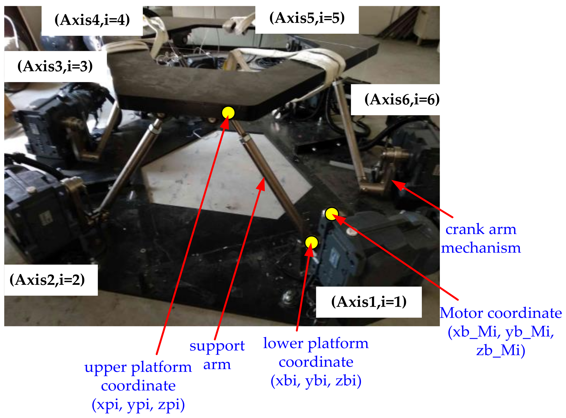
2.2. Proposed Inverse Kinematics

Because traditional inverse kinematics methods fail in the position control implementation, the upper platform can only be moved approximately to adjust the length of the virtual support arm. To improve the movements of the endpoint coordinates of the motion platform crank arm, an actuating method similar to that of a linear actuator was adopted to obtain the relevant coordinates. The position of the linear actuator was set as the lower fixed point coordinate, and the upper platform coordinate could be changed by adjusting the elongation of six linear actuators. In practice, the elongation required by each electric cylinder can be calculated by subtracting the distance between the upper and lower platform coordinates with elongation from that without elongation. Therefore, this study proposes changing the motion platform of the rotary crank arm to the output end of the crank arm motor as the lower fixed point of the linear actuator, thereby determining di, which is the distance between the upper platform coordinate and the motor coordinate (xb_Mi, yb_Mi, zb_Mi). The vector of di is expressed as follows [21]:
d i = q i b i = T + R p i b i
where T is the position vector of the upper platform coordinate relative to the lower platform, R denotes the homogeneous transformation matrix, pi = [xpi ypi zpi] represents the position vector of the upper platform, bi = [xb_Mi yb_Mi zb_Mi] is the position vector of the motor rotation axis, and di denotes the equivalent rod length.
Thus, by taking into account the relationship between the lengths of the crank, connecting rod, and support arm, the positions of the motor end and upper platform were bi and pi, respectively, s was the sum of the connecting link length (p) and support arm length (l), and the contact coordinate (Ai) between s and the crank length (a) was projected to the xy plane. In Figure 3, ϕ i denotes the included angle between the x direction and the crank length. The known conditions, namely, s, a, Bi = [xb_Mi yb_Mi zb_Mi], pi = [xpi ypi zpi], and ϕ i , were used to calculate the angle required for each axis to rotate ( θ i ), thereby controlling the different virtual cylinder lengths (di), controlling the elongation of the virtual cylinder, and determining the platform attitude required by the 6DoF platform.
Because the six sets of crank arm mechanisms were arranged opposite to each other, they were divided into odd and even numbers. The first, third, and fifth axes were controlled at 0–180 degrees, while the second, fourth, and sixth axes were controlled at 180–360 degrees. The odd axes of Ai are expressed as
x a i = a cos θ i cos ϕ i + x b _ M i
y a i = a cos θ i cos ϕ i + y b _ M i
z a i = a sin θ i + z b _ M i
where i = 1, 3, and 5. The even axes of Ai are expressed as
x a i = a cos 180 θ i cos 180 + ϕ i + x b _ M i
y a i = a cos 180 θ i cos 180 + ϕ i + y b _ M i
z a i = a sin 180 θ i + z b _ M i
where i = 2, 4, and 6. As shown in Figure 3, Pythagorean theorem is applied to find s, di, and a, which are expressed as follows:
s 2 = x p i x a i 2 + y p i y a i 2 + z p i z a i 2
d i 2 = x p i x b _ M i 2 + y p i y b _ M i 2 + z p i z b _ M i 2
a 2 = x a i x b _ M i 2 + y a i y b _ M i 2 + z a i z b _ M i 2
Equations (11) and (12) are substituted into Equation (10) to derive
s 2 = d i 2 + a 2 + 2 x b _ M i 2 + y b _ M i 2 + z b _ M i 2 2 x p i x b _ M i + y p i y b _ M i + z p i z b _ M i + 2 x a i x p i x b _ M i + 2 y a i y p i y b _ M i + 2 z a i z p i z b _ M i
Equations (4)−(9) are substituted into (13) to derive
d i 2 + a 2 s 2 + 2 a sin θ i z p i z b _ M i 2 a cos θ i cos ϕ i x p i x b _ M i + sin ϕ i y p i y b _ M i = 0
To facilitate the calculation, the equation is rewritten as follows:
H = E sin θ i + K cos θ i
where
H = d i 2 + a 2 s 2
E = 2 a z p i z b _ M i
K = 2 a cos θ i cos ϕ i x p i x b _ M i + sin ϕ i y p i y b _ M i
Equation (15) belongs to the trigonometric identity, and θ i can be written as
θ i = sin 1 H / E 2 + K 2 tan 1 K / E
The aforementioned equation demonstrates that the actual rotation angles (19) of the six motors can be directly derived using the known conditions—s, a, bi = [xb_Mi yb_Mi zb_Mi], pi = [xpi ypi zpi], ϕ i , and the distance (di) from the upper platform coordinate to the motor coordinate.

3. PID Controller

In the synchronous d-q frame, the voltage equations can be expressed as
v d = r s i d + L d d d t i d ω r e L q i q
and
v q = r s i q + L q d d t i q + ω r e L d i d + ω r e λ m
where v d is the d axis voltage, v q is the q axis voltage, r s is the stator resistance, i d is the d axis current, i q is the q axis current, L d is the d axis inductance, L q is the q axis inductance, d / d t is the differential operator, ω r e is the electrical motor speed, and λ m is the flux linkage of the permanent magnet mounted on the shaft rotor. Through realizing i d = 0 by applying field-oriented control, Equations (20) and (21) can be rewritten as
v d = ω r e L q i q
and
v q = r s i q + L q d d t i q + ω r e λ m         = u q + ω r e λ m
The electro-magnetic torque is
T e = 3 2 P 2 λ m i q = K T i q
where T e is the electro-magnetic torque of the motor, P is the number of poles of the motor, and K T is the torque constant. The mechanical speed and position of the motor are expressed as
d d t ω r m = 1 J t T e T L B t ω r m
and
d d t θ r m = ω r m
where ω r m is the mechanical speed, θ r m is the mechanical position, J t is the total inertia of the motor and gearbox, T L is the load torque, and B t is the total viscous coefficient of the motor and gearbox. The electrical position and speed, which can be expressed as θ r e and ω r e , are shown as follows:
θ r e = P 2 θ r m
and
ω r e = P 2 ω r m
The PID control law is
u = K P e t + K I e t d t + K D d d t e t
where e t , K P , K I , and K D are the control error, proportional, and integral coefficients, respectively. In Figure 4, G θ , G ω , and G C of the servo driver are the PID controllers, namely, the position loop, speed loop, and current loop controllers, respectively. The control system was designed and applied to each of the six actuators independently.

4. Monitoring System Design

The six-axis platform monitoring module was developed exclusively for six-axis platform testing. The industrial computer monitoring program was designed under the LabVIEW environment and the interactive property is good. The function of the system reached the expected design requirements, and the cost is low. Combined with the modular design concept, it is integrated in the waterproof box shown in Figure 5. The waterproof box contains a high-speed DAQ, an industrial computer, a touch screen, sensors, professional wiring harnesses, and jigs. The special jig allowed for convenient and rapid installation. Measurement software was written to measure and record various parameters of the six-axis motion platform at high speed.

4.1. Gyroscope and Angular Velocity Meter Jig

Three angular velocity sensors were fixed on the cube to measure angular velocity in the x, y, and z directions. The attitude gyroscope and the cube were fixed on a magnetic bottom plate, the magnetic attraction was approximately 47 kg. The adherence distance was adjusted using three screws to avoid the strong impact of direct magnetic adherence from damaging the sensors. Two powerful magnets at the bottom of the jig were adhered to the six-axis platform to be tested. To avoid the impact of powerful magnetic adherence, three knobs were designed. Before adherence, the knobs were turned clockwise to the end such that the three screw threads formed three points of support. After aligning with the x direction of the platform, the jig was adhered to the platform, and the three knobs were turned counterclockwise for the bottom plate to fit closely to the platform, the jig was thus firmly adhered to the platform. The jig could be easily dissembled by turning the three knobs clockwise to the end, as shown in Figure 6.

4.2. Laser Displacement and Angular Meters

Three three-section brackets (Figure 7a) were used to adjust the height of the x, y, and z axes of the measurement platform, while three measurement reference plates (Figure 7b) were magnetically adhered to the x, y, and z axes of the six-axis platform. The positions of the brackets or reference plates were adjusted for a red laser dot fired out of the laser displacement meter to hit near the center of the reference plate. Because the six-axis platform had a hexagonal structure design when viewed from above, the x axis was adjusted for the measurement reference plate to magnetically adhere to the x direction, and the x direction displacement was immediately read when the laser hit the measurement reference plate. The y axis was not perpendicular to any plane. Therefore, the reference plate was installed on the side of the six-axis platform, and y direction displacement was obtained through angle correction. The correction method is shown in Figure 7c.

4.3. Measurement Software

Figure 8a presents the measurement software setting form, which allows for archive path and measurement speed settings. The five sensor-related settings are as follows: angular velocity sensor and laser displacement meter receiving signals from the voltage input channels (the software enables or disables the function as well as adjusting the channel name, scale, offset, and unit), three-axis accelerometer receiving signals from the IEPE channel (the software enables or disables the function as well as adjusting the channel name, sensor sensitivity, and unit), and attitude gyroscope receiving signals from the RS232 serial port (the software sets the communication port). Figure 8 presents the real-time curve and trend curve for the sensor signals received by the high-speed DAQ. The left side of Figure 8b is the channel display. The operator can manually select the number of measurement channels for continuous and simultaneous measurement, display, and archiving.

5. Implementation

The implementation block diagram of the platform is displayed in Figure 9. The mechanical structure of the platform was designed to carry a simulator cab of 1500 kg or heavier (Figure 10a). The platform mechanism was divided into upper and lower platforms. The six support arms of the platform achieved the 6DoF stroke required by the simulator cab through crank arm rotation. Fisheye bearing joints were used to connect the upper end of the support arm to the upper platform, while the lower end of the support arm was coupled with the crank arm to drive the upper platform. The prototype of the crank mechanism is shown in Figure 10b. The dimensions are link length = 105 mm, support arm length = 835 mm, and crank length = 250 mm. The parameters of the motor are shown in Table 1. The gearbox ratio is 32.41. The servo motor was connected with a gearbox to magnify the torque output. A motion control card PMDK, produced by ICP Das Co., Ltd, was used with a 5-V PCI bus. The PMDK had six pulse input and output channels, six analog input and output channels, and various digital input and output channels. The PMDK was equipped with a two-wire FRnet IO module, which can be used for remote input and output control.
The monitoring module is shown in Figure 11a,b. The operator opened the waterproof storage box, screwed one end of the wiring harness to the input and output connector and the other end to sensor a, and secured the measurement reference plates and three-section brackets in place (Figure 11a). Figure 11b displays the positions of the angular velocity meter and the gyroscope.
The main program conducts the initial setup, thread enabling, and mode login of the platform. Figure 12a contains a flowchart of the implementation. Under the normal mode, the login mode can be selected using the human–machine interface. When the operator discovers an abnormal alarm or when maintenance personnel need to inspect the electric cylinders, they may select the maintenance mode via the interface. Data can be read and written via Internet transmission, and a thread of network modules is produced (Figure 12b). Operators can issue 6DoF commands to the platform and transmit the 6DoF commands to the platform computer by using Internet cable transmission.

6. Experimental Validation

Figure 13 contains photographs of the four strokes under the control of 6DoF. This section validates the accuracy and feasibility of the proposed method by using experimental results. Traditional inverse kinematics and the proposed inverse kinematics were written into the software—only the inverse kinematics software was modified, the hardware was not—to compare the motion of the six-axis crank arm platform when the two algorithms were applied. Then, 6DoF commands were issued to the platform through the human–machine interface, and the movable range of each DoF was recorded.
Figure 14a–c are records of the relevant measurement results. The controllable angles of the two algorithms were compared, as indicated in Figure 14a. Because the traditional method used the trial-and-error method to control the lower platform coordinate, when the calculated rod length approximated the actual rod length, the movement was completed. The traditional method allowed the actuator to be operated only within the linear region, that is, a position of 60 to 180 degrees. The proposed method opted to directly map the crank arm platform to the Stewart platform, enabling the actuator operating region to reach 50 to 230 degrees. A comparison of the algorithms is presented in Figure 14b, where the subscripts “old” and “new” denote the traditional and proposed methods, respectively. As in the figure, the movable range of the proposed method was larger than that of the traditional method—a front–back distance 60 mm longer, a left–right distance 80 mm longer, and a vertical distance 160 mm longer, which effectively improved the stroke of the platform operation space. The algorithms’ controllable angles of rotation—known as roll, pitch, and yaw—were compared, as in Figure 14c. The angles of rotation of the proposed algorithm were wider than those of the traditional algorithm—8 degrees wider in roll, 4 degrees wider in pitch, and 4 degrees wider in heave. An enlarged operating angle implies an increased overall platform space. Figure 12a,b are the 2 DoF ± 300 mm displacement response diagrams, where the motion control command begins at 8 s with a period of 4 s. To observe the relationship between surge and sway—a 90-degree difference—more clearly, they were plotted on the horizontal and vertical axes, respectively, forming a perfect circle (Figure 15b). Figure 16a–c present the displacement, velocity, and acceleration curves of surge conducting 150 mm of forward and reverse rotation, and the velocity was obtained using differential software. Platform operation involved complex mechanical parts as well as the simulator cab. Accordingly, a few spikes were observed in the differential velocity due to discontinuous displacement. Figure 17a,b are the response diagrams of the three translational DoF (surge, sway, and heave) at ±300 mm displacement with an angular difference of 120 degrees between any two. Regarding heave, the laser light of the displacement meter hit the rear of the upper platform. Due to the unfavorable mechanism smoothness, ripples were observed in the extracted signals. A 3D circle was formed when the three translational DoF were spatially plotted. Figure 18a–d are the response diagrams of the three other DoF at ±26 degrees with an angular difference of 120 degrees between any two. In Figure 18b, RS232 is used to read the angular velocity of the gyroscope, which has an amplitude of ±12 degrees/s. The roll, pitch, and yaw were spatially plotted, forming a 3D circle. Figure 19 shows the x, y, and z axis accelerations of the test platform, and the impulse responses were captured by the accelerometer. The platform performed x axis acceleration and deceleration alternately at 5–15 s, and the acceleration was approximately 0.5 g, whereas the platform performed y and z axis acceleration and deceleration alternately at 22–23 s and 43–55 s, respectively, and the acceleration was also approximately 0.5 g.

7. Conclusions

This study discussed the inverse kinematics of a six-axis motion platform, and the development of a monitoring system. The main contribution of this study is the design of a 6DoF crank arm mechanism to replace the expensive 6DoF linear actuator Stewart platform, 3DoF crank arm platform, and 4DoF crank arm platform, and the result of obtaining a comparable movement experience to the Stewart system. The algorithm was applied to the motion control of a 6DoF platform to control the elongation of the virtual cylinder and to determine the platform attitude required by the 6DoF platform. Unlike the conventional method, which relies on approximation to obtain the required angle, this study proposed a more accurate, real-time, and highly dependent processing method. In addition, this study used LabVIEW to create a set of testing equipment that integrates different sensors and jigs to read the angle, angular velocity, displacement, and linear acceleration of the platform in motion. Subsequently, the differential equation and sampling rate were used to calculate the angular acceleration and linear velocity. The testing equipment data were transmitted to the platform computer via RS-485 or RS-232 digital communication, allowing the platform to control the state of motion at all times. Finally, the experimental results prove the proposed algorithm capable of improving the operation of the platform stroke and thus applicable to simulators with higher specification requirements. Moreover, the implementation of the platform was based on the PID controller. Because of its simple structure, strong robustness, and good stability, the PID controller is still widely used in various fields of industrial control. However, the modern control theory of the platform is not the main topic of this study that will be considered to evaluate the design in future work.

Funding

This research received no external funding.

Conflicts of Interest

The author has no conflict of interest to declare.

References

  1. Urlahannan, A.; Jennings, P.; Oliveira, L.; Birrell, S. Designing an adaptive interface: Using eye tracking to classify how information usage changes over time in partially automated vehicles. IEEE Trans. Access 2020, 8, 16865–16875. [Google Scholar] [CrossRef]
  2. He, Z.; Lian, B.; Li, Q.; Zhang, Y.; Song, Y.; Yang, Y.; Sun, T. An error identification and compensation method of a 6-DoF parallel kinematic machine. IEEE Trans. Access 2020, 8, 119038–119047. [Google Scholar] [CrossRef]
  3. Nabi, H.N.; Ullah, S.; Munir, A. Kinematics analysis of three-degree-of freedom parallel manipulator with crank arm actuator. In Proceedings of the 2014 11th International Bhurban Conference on Applied Sciences & Technology (IBCAST), Islamabad, Pakistan, 14–18 January 2014; pp. 182–188. [Google Scholar]
  4. Pan, C.T.; Sun, P.Y.; Li, H.J.; Hsieh, C.H.; Hoe, Z.Y.; Shiue, Y.L. Development of multi-axis crank linkage motion system for synchronized flight simulation with VR immersion. Appl. Sci. 2021, 11, 3596. [Google Scholar] [CrossRef]
  5. Stewart, D. A platform with six degrees of freedom. Proc. Inst. Mech. Eng. 1965, 180, 371–386. [Google Scholar] [CrossRef]
  6. Fichtert, E.F. A Stewart platform-based manipulator: General theory and practical construction. Int. J. Robot. Res. 1986, 5, 157–182. [Google Scholar] [CrossRef]
  7. Mohammed, M.G.; Duffy, J. A direct determination of the instantaneous kinematics of fully parallel manipulators. ASME J. Mech. Transm. Autom. Des. 1986, 107, 226–229. [Google Scholar] [CrossRef]
  8. Liu, K.; Fitzgerald, J.M.; Lewis, F.L. Kinematic analysis of a Stewart platform manipulator. IEEE Trans. Ind. Electron. 1993, 40, 282–293. [Google Scholar] [CrossRef]
  9. Ji, C.Y.; Chenand, T.C.; Lee, Y.L. Investigation of kinematic analysis and applications for a 3-RRPS parallel manipulator. J. Chin. Soc. Mech. Eng. 2007, 28, 623–632. [Google Scholar]
  10. Mohammed, A.M.; Li, S. Dynamic neural networks for kinematic redundancy resolution of parallel Stewart platforms. IEEE Trans. Cybern. 2016, 46, 1538–1550. [Google Scholar] [CrossRef] [PubMed]
  11. Lara-Molina, F.A.; Rosario, J.M.; Dumur, D. Architecture of predictive control for a Stewart platform manipulator. In Proceedings of the 2010 8th World Congress on Intelligent Control and Automation, Jinan, China, 7–9 July 2010; pp. 6584–6589. [Google Scholar]
  12. Bruschetta, M.; Maran, F.; Beghi, A. A Nonlinear, MPC-based motion cueing algorithm for a high-performance, nine-DoF dynamic simulator platform. IEEE Trans. Control Syst. Technol. 2017, 25, 686–694. [Google Scholar] [CrossRef]
  13. Asadi, H.; Mohammadi, A.; Mohamed, S.; Qazani, M.R.C.; Lim, C.P.; Khosravi, A.; Nahavandi, S. A model predictive control-based motion cueing algorithm using an optimized nonlinear scaling for driving simulators. In Proceedings of the 2019 IEEE International Conference on Systems, Man and Cybernetics (SMC), Bari, Italy, 6–9 October 2019; pp. 1245–1250. [Google Scholar]
  14. Tang, Z.; Hu, M.; Pei, Z.; Liu, L.; Zhang, J. A new numerical method for Stewart platform forward kinematics. In Proceedings of the 2016 35th Chinese Control Conference (CCC), Chengdu, China, 27–29 July 2016; pp. 6311–6316. [Google Scholar]
  15. Lou, J.H.; Tseng, S.P. Developing a real-time serial servo motion control system for electric Stewart platform. In Proceedings of the 2014 International Conference on Advanced Robotics and Intelligent Systems (ARIS), Taipei, Taiwan, 6–8 June 2014; pp. 66–71. [Google Scholar]
  16. Qazani, M.R.C.; Asadi, H.; Khoo, S.; Nahavandi, S. A linear time-varying model predictive control-based motion cueing algorithm for hexapod simulation-based motion platform. IEEE Trans. Syst. Man Cybern. Syst. 2019, 51, 6096–6110. [Google Scholar] [CrossRef]
  17. Asadi, H.; Lim, C.P.; Mohamed, S.; Nahavandi, D.; Nahavandi, S. Increasing motion fidelity in driving simulators using a fuzzy-based washout filter. IEEE Trans. Intell. Veh. 2019, 4, 298–308. [Google Scholar] [CrossRef]
  18. Available online: https://docplayer.net/34514506-How-to-build-an-arduino-powered-6dof-motion-platform.html (accessed on 26 August 2021).
  19. Urlahannan, A.; Jennings, P.; Oliveira, L.; Birrell, S. A efficient numerical method for forward kinematics of parallel robots. IEEE Trans. Access 2019, 7, 128758–128766. [Google Scholar]
  20. Jia, G.; Pan, G.; Gao, Q.; Zhang, Y. Research on position inverse solution of electric-driven Stewart platform based on Simulink. J. Eng. 2019, 2019, 379–383. [Google Scholar] [CrossRef]
  21. Sciavicco, L.; Siciliano, B. Modelling and Control of Robot Manipulators; Springer: London, UK, 2000. [Google Scholar]
Figure 1. Photograph of the motion platform.
Applsci 11 09330 g001
Figure 2. The schematic diagram of axis1 control.
Applsci 11 09330 g002
Figure 3. The relationship of axis i (i = 1–6) and upper platform coordinate.
Applsci 11 09330 g003
Figure 4. Block diagram of the position control system.
Applsci 11 09330 g004
Figure 5. Photograph of the monitoring system.
Applsci 11 09330 g005
Figure 6. Gyroscope and angular velocity meters.
Applsci 11 09330 g006
Figure 7. Laser displacement meter: (a) three-section bracket, (b) measurement reference plate, and (c) schematic diagram of x axis and y axis measurement.
Applsci 11 09330 g007
Figure 8. Operation interface: (a) software setting and (b) channels display.
Applsci 11 09330 g008
Figure 9. The block diagram of the 6DoF platform.
Applsci 11 09330 g009
Figure 10. 3D design drawing of the 6DoF platform: (a) 6DoF platform, and (b) crank arm mechanism.
Applsci 11 09330 g010
Figure 11. Photograph of the implementation system: (a) monitoring module and (b) upper platform.
Applsci 11 09330 g011
Figure 12. Flowchart of the implementation: (a) main program and (b) network module.
Applsci 11 09330 g012
Figure 13. The control of 6DoF: (a) heave, (b) pitch, (c) roll, and (d) surge.
Applsci 11 09330 g013
Figure 14. Comparison of the proposed method and the conventional method: (a) control range, (b) surge, sway, and heave, and (c) roll, pitch, and yaw.
Applsci 11 09330 g014
Figure 15. Measured displacement responses: (a) responses and (b) trajectories.
Applsci 11 09330 g015
Figure 16. Measured triangular wave displacement responses: (a) displacement, (b) velocity, and (c) acceleration.
Applsci 11 09330 g016
Figure 17. Measured responses at different time-varying commands: (a) 2D view and (b) 3D view.
Applsci 11 09330 g017
Figure 18. Measured sine wave degree responses: (a) angle, (b) angular velocity, (c) angular acceleration, and (d) 3D view.
Applsci 11 09330 g018
Figure 19. Measured acceleration responses: (a) x axis, (b) y axis, and (c) z axis.
Applsci 11 09330 g019
Table 1. The parameters of the motor.
Pole Number8 Pole
Power dissipation5.0 kW
Rated voltage220 V
Rated load current25.9 A
Rotor inertia0.00488 Kg-m2
Rated speed2000 r/min
Maximum speed3000 r/min
Rated torque23.9 N.m
Maximum torque71.6 N.m
Publisher’s Note: MDPI stays neutral with regard to jurisdictional claims in published maps and institutional affiliations.

