Article

Using a Cable-Driven Parallel Robot with Applications in 3D Concrete Printing

by
Tuong Phuoc Tho
and
Nguyen Truong Thinh
*
Department of Mechatronics, HCMC University of Technology and Education, Ho Chi Minh 700000, Vietnam
*
Author to whom correspondence should be addressed.
Appl. Sci. 2021, 11(2), 563; https://doi.org/10.3390/app11020563
Submission received: 14 December 2020 / Revised: 30 December 2020 / Accepted: 5 January 2021 / Published: 8 January 2021
(This article belongs to the Section Mechanical Engineering)

Abstract

:
In construction, a large-scale 3D printing method for construction is used to build houses quickly, based on Computerized Aid Design. Currently, the construction industry is beginning to apply quite a lot of 3D printing technologies to create buildings that require a quick construction time and complex structures that classical methods cannot implement. In this paper, a Cable-Driven Parallel Robot (CDPR) is described for the 3D printing of concrete for building a house. The CDPR structures are designed to be suitable for 3D printing in a large workspace. A linear programming algorithm was used to quickly calculate the inverse kinematic problem with the force equilibrium condition for the moving platform; this method is suitable for the flexible configuration of a CDPR corresponding to the various spaces. Cable sagging was also analyzed by the Trust-Region-Dogleg algorithm to increase the accuracy of the inverse kinematic problem for controlling the robot to perform basic trajectory interpolation movements. The paper also covers the design and analysis of a concrete extruder for the 3D printing method. The analytical results are experimented with based on a prototype of the CDPR to evaluate the work ability and suitability of this design. The results show that this design is suitable for 3D printing in construction, with high precision and a stable trajectory printing. The robot configuration can be easily adjusted and calculated to suit the construction space, while maintaining rigidity as well as an adequate operating space. The actuators are compact, easy to disassemble and move, and capable of accommodating a wide variety of dimensions.

1. Introduction

Currently, the technology of rapid prototyping, 3D printing, machining with CNC machines, factory automation with robots, and monitoring and control over the internet is being widely applied to reduce production and labor costs, as well as to increase productivity and consistency [1,2,3,4,5]. Meanwhile, the traditional construction field has been slow to integrate modern technologies into its processes. In developed countries, the traditional concrete mixing and casting method of building parts at the construction site has been replaced by being prefabricated in a factory and then transferred to the construction site for assembly. This allows for a specialization construction process and shortens the construction times, increasing the quality and stability of the building. However, this option is not suitable for single houses with different designs; the size of the prefabricated parts is also limited due to transport problems. Additive manufacturing (AM)—an appropriate name to describe the technologies that build objects by adding layer-upon-layer of material, such as plastic, metal, concrete, combined with the assistance of computers for the calculation, design, and simulation of the structure—optimizes the shape design and distributes the material appropriately so that the structure meets the technical requirements with the lowest amount of material. When applying 3D printing technology in construction, we can save the costs of the concrete form work and mold installation time, thus shortening the project implementation time. Many fast prototype printers (3D printers) can work continuously, thereby project costs can be significantly reduced. By adopting 3D printing techniques in the construction industry, it is possible to reduce labor and construction time, improve quality, and reduce the environmental impact and health of workers. The construction 3D printing technology for building a layer-by-layer construction [1] is known as additive manufacturing (AM). Lim et al. [2] investigated the additive manufacturing processes in construction and reviewed large-scale additive manufacturing processes that have been applied in the construction and architecture sectors for concrete printing, based on the principle of automatic material extrusion. In that paper, the wet properties of the material were considered, as it had a great influence on the product’s success. The paper also proposed several new criteria for the classification of specific parameters of this process. Three processes were considered for different applications and materials, including the D-Shape process—uses a powder deposition process, which was selectively hardened using a binder; Concrete Printing—based on the extrusion of cement mortar; and Contour Crafting—build large-scale objects with a smooth surface finish by the layered printing method based on the printing process with a trowel. The authors have analyzed the Concrete Printing procedure in detail, showing many advantages, such as being responsive to a design with complex profiles, achieving a high accuracy, and saving a lot of labor costs. It is difficult to do with conventional construction processes.
Different materials can be used for 3D printing, with equipment sizes range from small to large, corresponding to many types of products such as statues, houses, vehicles, and boats. Some structures have been studied and used for large 3D printing, such as cartesian structures, serial robots, and cable parallel robots, as shown in several studies. Zhang et al. [3] proposed a 3D printing system that employs two mobile robots with industrial robots printing concurrently a large, one-piece structure; the system consists of two 6-axis industrial robots with a reach of 0.9 m and repeatability accuracy of 0.02 mm, placed on two holonomic mobile robots; two printing nozzles also was designed and attached to the robots, connected with a pump. The mobile robot is equipped with wheel encoders, an inertial measurement unit (IMU), and 2D laser scanner sensors for localization and odometry. The robots are controlled, positioned, and the motion trajectory set to work for each specific print object. Izard et al. [4] showed the combination of the Cogiro cable-driven parallel robot (CDPR) (Cogiro is a suspended CDPR owned by Tecnalia and CNRS-LIRMM—Tecnalia France, 950 rue Saint-Priest, 34070 Montpellier, France) with the material extruder of the Pylos project (IAAC 2013) [5]; this system opens the opportunity to make a large 3D printing machine with a workspace of 13.69 × 9.49 × 3.3 m. Pylos is the product of a study at IAAC on 3D printing nozzles and materials for large-scale construction; the system is designed for extruding the construction materials. The material studied in this topic is from naturally sourced building materials and biodegradable, intended for printing in buildings. This material is the combination of a soil-based blend with a natural additive specially formulated to suit the extrusion of materials for construction, with improved tensile strength and viscosity. The material extruder is designed to consist of a material canister with a volume of 15 L; the extruded force is generated by a pneumatic cylinder. The print layer size is adjustable, with a layer thickness of 1–7 mm, width of 6–30 mm, and corresponding printing speed of 0.05–1 m/s. Its original point of design resides in the way the cables are connected to the frame, which makes it a very stable design, as studied by Gouttefarde et al. [6]; this system is controlled by a G-Code post-processor module. In the study, the authors’ cable-suspended parallel robot geometries relied on their quasi-static behavior, based on a particular wrench-feasibility analysis; the authors used a performance index, which is the maximum acceptable distance between the geometry center of the mobile platform and the center mass of the set consisting of the platform and payload. This performance index is used in determining the geometry of cable robots for heavy load handling applications, so that the ratio between the workspace and the size of the robot is large.
Research into cable-driven parallel robots is an area of great interest in the field of robotics. Cable-driven parallel robots typically have greater load capacity, larger operating space, and, in particular, simpler portability and construction compared to traditional parallel robots like Hexapods, Delta robots, and serial robots [4,7]. A CDPR (Figure 1) includes a moving platform (end-effector), cables, winches, and a base frame, with the cables being actuators used to connect the moving platform and base frame to which the winches are attached. The end-effector is moved by changing the length of the cables; this structure has a lot of advantages, especially when the moving platform is required to move at high acceleration because the weight of actuator is small. We also can put any load attaching moving platform CDPR to perform the different tasks during service and industrial activities. Furthermore, CDPRs have a flexible structure that can be easily reconfigured according to the workspace. CDPR frames can be factory frames, surrounding structures, or removable steel frames; this feature is particularly suitable for the construction of buildings due to construction sites and spaces being different. The weights of the winches are usually small compared to the large cable lengths, as well as convenient to move and install. However, certain problems, such as the complex dynamics and operating space, sagging of the cable over a large working distance, and the equilibrium status of the moving flatform under external impact forces and positive cable tension conditions, are challenges to overcome when modeling and designing the cable robot controller, to ensure that the MP(moving platform) moves precisely according to the desired trajectory and with the required firmness.
Some application projects of cable robots had extremely large operating spaces of up to hundreds of meters. The SkyCam system developed by August Design in 1980 [8] was widely used for live broadcasts. The camera in a SkyCam was suspended by four cables; its speed can be up to 44.8 km/h, and high-speed photography was possible with SkyCam on a large scale. This structure controls the robot to move the camera by tracking any target in the stadium with a high velocity; the installation time has also been shortened as the points on the stadium dome can be used as cable ties. In 1999, a feed support system in a 500-m aperture spherical radio telescope (FAST) was developed by Duan et al. in China [9]; this system consisted of six cables placed on six columns and connected to a feed cabin as the moving platform, where the position of the feed cabin was controlled by the six cables. The authors analyzed the static and dynamic problem of the cable suspension model with random wind load. In a nonlinear static model, the value and orientation of the tensions can be obtained by the equilibrium equation to specify the position of the moving points. In a dynamic analysis, the finite element was used to solve the dynamic equation.
In this paper, we propose an automatic concrete 3D printing system based on the CDPR configuration. Part 1 is a synthesis of related studies on large 3D printing, with studies on the materials and additives for automatic concrete extrusion structures. The analyzed synthesized method is used to propose research issues, such as the design and calculation of a 3D concrete printing system with a cable robot, problems in calculating and designing the cable robot configuration, and investigating the workspace of the CDPR based on the pseudo-static equilibrium problem when the robot moves at a low speed, thereby calculating the tension forces according to the printed trajectories and calculating the matching variable values, which are the length of the cable with the impact tension forces and cable deflection, forming the cable robot control signal according to the given trajectory. The main contribution of this study is to propose a flexible 3D concrete printing system on the basis of CDPR with two efficient algorithms used to calculate the workspace, check the trajectory in the workspace for each specific configuration of the CDPR, and calculate the cable tension that satisfies the conditions of a quasi-static equilibrium condition, forces limit, load variation, and cable sagging, thereby calculating the control differences as to the length of the cables according to each given path.
The mechanical structure of the CDPR is designed and analyzed in Section 2, and the quasi-static workspace is determined with a linear programming algorithm, taking to account the change of payload when printing. Section 3 shows the process of optimizing the tensions of the cables with the dual simplex algorithm. The results of this process and the kinematic problem are used to solve the cable sagging problem, to specify the value of the length of the cables, with the offset sagging values, in Section 4. Section 5 presents the mechanical design of the 3D concrete printing system based on CDPR; the structures of the cable winch and concrete extruder are designed and calculated to be suitable for the specification of this system. Section 6 shows the experimental result of this system. Parameter calculations are used to control the system to perform the printing trajectory.

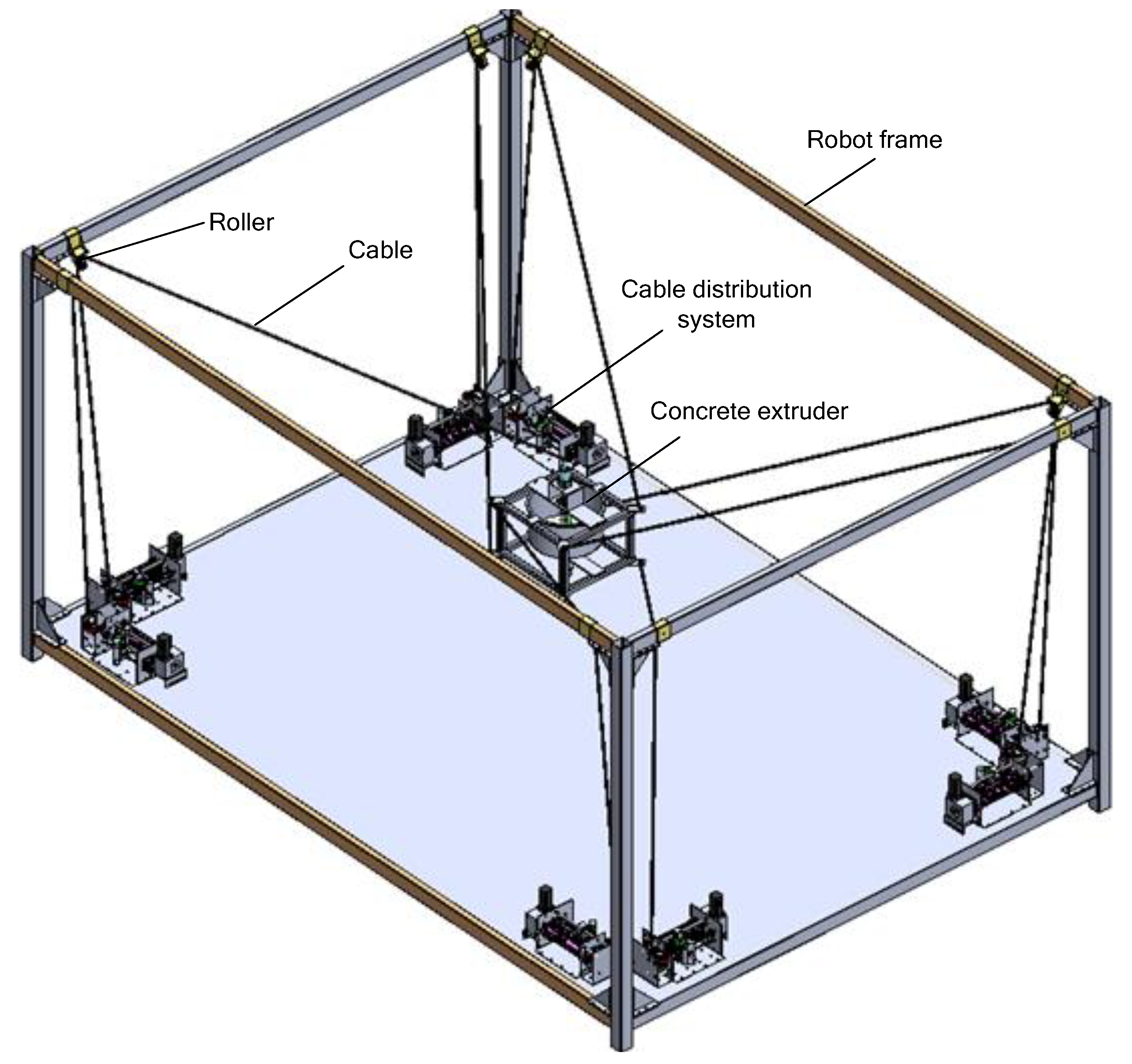
2. Mechanical Structure

2.1. Architecture of the Model

The structure of a CDPR was researched to find the different configurations for multi-purpose applications [7]; an optimal design of a CDPR usually relate to one which has the largest workspace, the fewest singularities, large force output, high stiffness throughout its workspace, high accuracy, etc. Designing the robot configuration so that it ensures the largest working space, with the constraints of size, flexibility, and load, is the main goal in cable robot designs. The optimized design performance index is a term that describes methods of comparing the optimal design properties of a design configuration compared to other investigated configurations or other robots. A commonly used performance index is the global condition index (GCI) [10], which is a measure of the kinematic dexterity of the robot over the whole workspace.
The robot classification is based on the topology of structure into serial and parallel robots. A sequence of joints and links is called serial robots or manipulators and, when there are more than one kinematic chains connecting to the end-effector of platform, it is called a parallel robot or closed kinematic chains. The CDPR is a special type of parallel robot with m being the number of cables and n being the degree of freedom of the CDPR moving platform. We have m < n + 1 being an under-constrained robot; m = n + 1 is a fully-constrained robot; and m > n + 1 is a redundantly constrained robot [7,11]. The inverse kinematics of the CDPR are much easier to analyze than the forward kinematics as well as the singularities affecting the robot in a similar way. The structure of a CDPR can be briefly described as follows: m cables are connected the m corners of a moving platform in three-dimensional Cartesian space; when changing the length of cables, the moving platform coordinates also change. We always consider the structure of the CDPR to inhibit the degree of rotation, because the weight of the moving platform plays a role, such as an external force that affects the tension and moves in the vertical axis.
The workspace of a robot is an important attribute; it affects how the robot is designed to be suitable for its actual use. The workspace of some types of robots, e.g., a cylindrical robot and gantry robot, can be described with simple geometric primitives such as a cylinder or rectangle. For serial robots, to define the workspace, we can give the basic parameters, such as the length, height, width, radius, kinematic chain, and the limits of the joints. The workspace description gets more complicated when considering translation and orientation or taking into account the dexterity of the robot. For ease of understanding, the workspace model should be simple; however, the topology of the rotation group is not isomorphic to the Cartesian space. Unfortunately, the motion is more complex for parallel robots and especially for cable robots where translation and orientation are strongly coupled. However, since most application engineers have a simple representation of the workspace in mind, one may have to finally reduce the used workspace of a robot to a subset that can be represented by a geometric primitive, such as a box, a cylinder, or a sphere.
Cable-driven parallel robots are able to generate high velocities and accelerations due to the very small inertia of their moving parts and cables. Furthermore, a large workspace and high payloads are possible due to efficient force transmission through the cables. A dynamic model extends the kinematic considerations by explicitly taking into account the influence of time on the behavior of the mechanical and also electrical subsystems of the cable robot. The fundamental geometric relations between the fixed base, the mobile platform, and the cables are the foundation of kinematic and static modeling. These nonlinear equations formulate the velocity and acceleration transmission of the robot, and which are employed to characterize the behavior of the robot. In the forward dynamic model, we have the input forces and torques to map the output motion of the cable robot, where the motion can be described as a position, velocity, or acceleration of joints, points, or bodies. The inverse dynamics characterizes the reverse mapping, where the motion is given and the forces and torques that generate this motion are sought. A cable robot is a mechatronic system consisting of a mechanical part and an electrical part. The mechanical part includes the mobile platform that is connected by m cables guided by pulleys to the winches. The electrical part consists of m servomotors, position controllers, and a central controller to compute the value of the variable control signals from the calculation results of the kinematic and dynamic problems.
To derive the equations of motion for the mechanical components of a cable robot, one can use recursive Newton–Euler equations or Lagrange equations of the second kind. Both mechanical principles are equivalent and result in equivalent equations. The proposed dynamic model is formulated in the operational space (Cartesian space) and it employs inverse kinematics and forward dynamics, which are easy to solve and fast to compute. Based on this approach, the equations can be set up in closed-form, such that computation is basically possible in real-time. However, when actually computing the equations of motion, the methods differ in how simple they are to use, taking into account the different kinds of cable models and subsystems.

2.2. Kinematics Problems

The kinematics problems of CDPRs describes the relation of the variable joints (length of the cables) and the pose of the moving platform. Figure 2 illustrates the kinematic structure of the eight cables parallel robot, where Ai and Bi (i = 1,…,n) are the two attaching points of the ith cable to the moving platform and the base, respectively; ai represents the position vector of Ai in the base or B-frame; and bi represents the position vector of Bi in the moving platform or E-frame. In this Figure, variable vectors li denote the length of the cable; ri corresponds to the position vectors; and Ri corresponds to the rotation matrix that denotes the orientation of the mobile platform. The combination of the orientation matrix R and the position vector r correspond to the E-frame of the moving platform on the base frame. The inverse kinematics of the cable robot can be written as
a i r R b i = l i
Rotation matrix R from the E frame to B frame can be obtained as follows:
R = R z ( γ ) R y ( β ) R x ( α ) = [ c γ c β c γ s β s α s γ c α c γ s β c α + s γ s α s γ c β s γ s β s α + c γ c α s γ s β c α c γ s α s β c β s α c β c α ]
In Equation (2), “s” denotes the sine, while “c” denotes the cosine of its indexed argument. Moreover, α, β, and γ stand for the angles of rotation of the x, y, and z axes. Multiplying the two sides of Equation (1) with their transpose leads to the following:
l i T l i = ( a i r R b i ) T ( a i r R b i )
So, the inverse kinematic for each cable of the CDPR is
| l i | 2 = | a i | 2 + | r | 2 + | R b i | 2 2 a i ( r + R b i )

3. Analysis of the Workspace of the CDPR

The workspace of parallel cable-driven mechanisms depends on various factors, such as the dimension of the base frame and moving platform, payload, cable configuration, and cable characteristics; on the other hand, the condition of the cable tension forces is non-negative, causing many difficulties and challenges for defining the workspace. This problem has been the subject of several studies and, recently, efficient methods that allow determining the workspace of parallel cable-driven mechanisms have been proposed [10]. Sheng et al. [11] proposed an efficient way of determining analytically the Wrench Closure Workspace (WCW) of spatially redundant cable-driven parallel mechanisms (CDPMs); the method was based on the boundary surface equations obtained from the null space of the structure matrix of a CDPM. Gouttefarde et al. [12] proposed a method to determine the cross of the WCW 6-degree-of-freedom (6-DOF) CDPR, corresponding to a specific orientation of the moving platform. This method was called the constant-orientation WCW (COWCW). Consequently, in case of 6-DOF mechanisms, only a partial workspace is obtained because three of the six posed variables must be fixed to compute the workspace. Another limitation of these methods lies in the difficulty taking into account the requirement of a minimum and a maximum tension in each cable (bounds on the allowed tensions), especially for 6-DOF mechanisms driven by more than six cables. Moreover, as a tool to design parallel cable-driven mechanisms, geometric methods seem to be limited to trial-and-error approaches.
The kinematic problem of CDPRS is not enough to control the position or force of the moving platform of the CDPRs. The cables cannot provide pushing forces but can only provide pulling forces. For CDPMs, the cable tension greatly affects the determination workspace. Figure 3 shows that, to balance any external wrench (Fp, Mp) applied on a moving platform, the cables must create tension forces, achieving equilibrium of the platform. The forces and torques acting on the CDPRs can be obtained from the following equilibrium equations:
i = 1 m τ i + F p = 0
i = 1 m ( b i × τ i ) + M p = 0
where Fp and Mp are the vectors of the external forces and torques acting on the mobile platform, respectively; τi is the force vector that each cable acts upon on the end-effector; and bi vectors are the positions of the distal attachment point Bi on the mobile platform relative to the origin of Op, given in local coordinates of the frame OP. From the cable direction show in Figure 3, with the unit vectors ui, the direction of the forces τi can be obtained as below.
τ i = τ i u i
Equation (7) represents the relationship between the kinematics, statics, and dynamics of the CDPRs; from (5) and (6) we can have
[ u 1 u m b i × u 1 b m × u m ] [ τ 1 τ m ] + [ F p M p ] = 0
by defining
A = [ u 1 u m b i × u 1 b m × u m ]
w p = [ F p M p ]
where τ = [ τ1 τ2 … τm]; Equation (8) can be rewritten as
A τ + w p = 0
where:
  • τ: vector of the cable tensions (m x1);
  • AT: Jacobian matrix of the CDPRs (n x m);
  • wp: vectors of the external wrenches applied on the center of mass of the mobile platform (n x 1).
The wrench closure workspace (WCW) of the CDPM defines a set of poses of the moving platform wherein the cables can balance any external wrench with positive tensions. Or, the WCW is the set of mobile platform poses that are wrench feasible; this means that with any wrench f in WCW, there exists a vector of cable tensions τ > 0 such that + f = 0.
From Equation (11), for each pose of the MB, it is necessary to calculate the combination of tension forces so as to balance it with the external forces, which can be obtained by inverting the AT matrix.
τ = ( A T ) 1 w p
Because AT is not square, a pseudo inverse-matrix can be used to solve this problem. There are some methods to determine the existence of an inequality system, with a solution or not, like pseudo inverse-matrix, linear programming, interval analysis, etc.
The cable configuration of the concrete printing cable robot with 6 DOF in this study is shown in Figure 4. The base frame, {B}, is located at the center of the lower surface of the robot frame. The MP is a rectangular frame connected to a robot frame by anchor points Ai and attach points Bi; li (or Lei according to the notation of this research) is the Euclidean norm cable lengths. In all cases i = 1, …, 8. This structure has no WCW because there is no set of cable tensions τ to satisfy the equilibrium Equation (11). The static workspaces of the cable robot are show in Figure 5, as determined by the linear programming algorithm; with this configuration, ignore the external forces, as the wrench force has only gravity force caused by the weight of the moving platform with the end-effector, so the workspace of the robot is proportional to the payload (weight of the moving platform and concrete). In the same configuration, when changing the payload placed on MB, the workspace also changes: the larger the payload, the wider the workspace. Based on this feature, a suitable trajectory can be designed, depending on the load.
This result shows that this configuration is suitable for printing purpose when the payload is large enough but do not exceed the upper limit of the tension. In the next sections, the MB and concrete extruded is designed with a total weight from 50 kg (without cement mortal) to 70 kg (full cement mortal).

4. Dual Simplex Algorithm for the Optimization of Cable Tension, Taking into Account Cable Sagging

When considering the effect of cable deflection (i.e., the weight of the cable) in the modeling, cable tension is related to finding the cable length, unlike the traditional straight line IPK problem. Therefore, the kinetic and pseudo-random problems are combined and must be solved simultaneously, which is obvious from Equations (8)–(10). This is a system of implicit nonlinear equations, so there is no analytical solution; thus, it is imperative to use numerical methods. References [13,14] show that, for cases of minimal or under constraints, the catenary Equations (8)–(10) are solved with equilibrium Equation (11). Gia Luan et al. [15] introduced a novel procedure to produce a quasi-static model and inverse kinematic model for CDPM with the presence of sagging by using both an analytic approach and empirical approach; this method is suitable for the low speed and low acceleration of the movement of the moving platform.

4.1. Optimization Cable Tension

In this study, a CDPR with 8 cables—6 DOF—was applied for the concrete printing. The velocity is very small, so we need to solve only the static equations. The static equilibrium equation of the MP can be used to obtain the cable forces Ti. With a feasible position, we can obtain infinite solutions, or there are existing and infinite valid combinations for τ; the physical interpretation of this case is that at a given position there are multiple valid ways of tensing the cables to maintain a static equilibrium because the number of cables is more the number of degrees of freedom. To obtain one desired solution out of these feasible solutions, mathematical techniques are used. To find a unique solution, this problem is solved as a constrained minimization problem. So, the statics problem is treated as a linear programming problem with the aim to minimize the cable tension. The problem is formulated as shown below.
Minimize objective function:
F = c T τ
Subject to constraints:
A τ = w p
0 ≤ τmin ≤ τ ≤ τmax
where c = [c1; c2;…; cn] ∈ Rn called n—dimension cost vector; τ = [τ1; τ2; …; τn] is the tension vector of the cables called n—dimension variable vector; A = (aij) ∈ Rm×n is a matrix of the constraint coefficients of the wrench matrix; −wp = bRm is an m-dimensional external force vector; and Tmin and Tmax are the minimum and maximum allowable cable tensions. This problem is a linear programming problem with eight variables, with the static equilibrium equations used as the constraints and bounds on the cable tensions based on the necessary conditions (T > 0). Bounds not only help in obtaining non-negative solutions (negative solutions for cable tensions means the cable is pushing, which is an unacceptable solution), but also restrict the solution to be within practical limitations, such as extremely high cable tensions, which might break the cable or overload the actuators (winches).
In this section, the dual simplex algorithm is used to find a set of solutions τ such that Function (13) has the smallest value to satisfy the constraints (14) and boundary conditions (15). In linear programming, we define the total cost F = cTτ: Rn→R as the objective value of the problem P(the primal problem) and the vector τ*, which minimizes the objective function F = cTτ*, while satisfying the equality condition Aτ* = −wp and 0 ≤ τminττmax is called the optimal solution of the problem P. Corresponding to the primal problem P, there exists a dual problem D, constructed according to the following method:
Minimize objective function: bTu subject to: ATuc with all u,
where u = (u1; u2; …; um) ∈ Rm is called the dual variables vector. Notice that if the dual problem of D is created, then the original primal problem P is also created. The relationship between problems P and D is established by the following three theorems [16,17].
Theorem 1.
Weak duality: If τ is a feasible solution of P, and u is a feasible solution of D, then bTucTτ.
Theorem 2.
Strong duality: If problem P has an optimal solution, then problem D also has an optimal solution. Moreover, the respective optimal solution values are equal to one another.
In Theorem 1, if there exists a pair of u and τ, making bTu = cT τ, then τ and u are solutions of P and D, respectively. Besides, a complementary slackness condition can be used to check the optimal property of τ and u. The complementary slackness condition is presented in Theorem 3.
Theorem 3.
Let τ and u be feasible solutions to P and D, respectively. Then, τ and u are the optimal solutions for each problem if and only if uT(b) = 0 and (cATu)Tτ = 0.
Theorem 3 can be used to establish the optimal property of a solution τ (τ 0); if problem B is in the standard form, this solution satisfies the first complementary slackness condition. Assume that τi > 0 form the second condition we obtain; we then obtain a system of equations, including the equations AijTu = ci corresponding to τi > 0. If the solution u satisfies the first constraint of the dual problem and the total cost is the same cost of the primal problem, then τ is an optimal solution to the original linear programming.
Three Karush–Kuhn–Tucker (KKT) conditions for a linear programming (LP) problem show on the following theorem:
Theorem 4.
KKT optimality conditions for LP: Given a linear programming problem P, the vector τ is an optimal solution to P if and only if there exist vectors u and r such that:
  • A τ = b; τ0 (primal feasibility);
  • ATu + r = c; r0 (dual feasibility);
  • rT τ = 0 (complementary slackness).
In this study, matrix A is of full rank m (m = 6 < n = 8). Let matrix B be the basic matrix created by six independent linear columns of AT and matrix N is a non-basic matrix containing the remaining two columns of A. The solution vector τ is separated into two parts, τB = B−1b = (τ1, τ2, …, τ6)T and τN = (τ7, τ8)T = 0, called the “basic” and “non-basic” solutions, respectively. The cost vector cT = [cB cN] is also partitioned into a basic cB and a non-basic cN matrix related to the solutions τB and τN. Assuming that u is the dual solution of the base matrix B, we have ATuc and uT = cTBB−1. Hence, the equality constraints of P are satisfied, since
A τ = B B 1 b + N . 0 = b
and the additional slackness is also satisfied, since
(cATu)T τ = cT τuTA τ = cTB−1bcTB−1b = 0
In this case, if xB0, then x is the optimal solution for P and all conditions of Theorem 4 are satisfied. If there is only a negative element in τ B, it will be eliminated by changing the basic B, thereby reducing the primal infeasibility. This procedure is repeated until all elements in xB are non-negative. This is the advantage of the dual simplex algorithm.
In this study, the mobile platform interpolates a printing trajectory with small velocity and acceleration, and the nonlinear effects due to rapid turning of the load are omitted to speed up the calculation. The external force Wp = −b can be simplified as
w p = [ F p M p ] = [ f x f y f z m x m y m z ] = [ 0 0 m g 0 0 0 ]
where m is the total mass of the concrete and the moving platform, and g is gravity acceleration. In the printing process, the mass of the concrete will decrease depending on the speed of the extruder.
m = ρ c f l o w e x t
where ρc, flowex, t are, respectively, the specific weight of the concrete, the flowrate of the extruder, and the interpolation time. With the Jacobian matrix A defined in (8), the dual simplex algorithm is used to find the set of tension τ that satisfies the optimal conditions with cable structure constrains. The result of this part, used as the input of the cable length computation process, takes into account cable sagging due to the CDPR applied for the concrete printing having 8 cables—6 DOF.

4.2. Cable Length Computation with Cable Sagging

The cable sagging model will assume that the cable is only deflected by its own weight, neglecting the wind and uneven weight distribution. Consider a cable suspended between two points B and M, as in Figure 4, where B is the base cable attachment point, M is the end-effector attachment point, LS is the straight-line (Euclidean norm) distance between A and B, L is the catenary (actual) length between B and M, g is the acceleration due to gravity, τ is the cable tension with the X and Z components τx and τz at the end effector side, τBx and τBz are the X and Z components of the cable tension at the base cable attachment point B, and (xm, zm) are the coordinates of the cable at the end-effect attachment point.
For the cable in Figure 6, the static catenary displacement equations for the inextensible case after simplification are as follows [13,15,18].
x m = | τ x | ρ L g [ sinh 1 ( τ z τ x ) sinh 1 ( τ z ρ L g L τ x ) ]
z m = 1 ρ L g [ τ x 2 + τ z 2 τ x 2 + ( τ z ρ L g L ) 2 ]
τ = τ x 2 + τ z 2
where ρL is the linear density of the cable material, and g is gravity acceleration.
When finding the active cable lengths for a given pose, considering the effects of cable sag (i.e., the mass of the cables), cable tension is involved in finding the cable length. Hence, the kinematics and statics (or quasi-statics when ignoring the dynamic problem of slow-motion control for printing concrete) problems are coupled and have to be solved simultaneously. The results of the kinematics and statics problems considers the cable lengths and cable tensions used as the input of the cable sag model (16–18). This system (16–18) is a nonlinear implicit equation and there are no analytical methods that can be applied to solve it. The numerical methods can be used to find suitable solutions.
The Trust-Region-Dogleg algorithm [19] is used to solve the cable sag model (18–20). Equation-solving definition: Given a set of n nonlinear functions Fi(x), where n is the number of elements in vector x, the goal of this algorithm is to find a vector x that makes all Fi(x) = 0. In this case, the cable sag model (18–20) is rewritten as
F i = { | τ x | ρ L g [ sinh 1 ( τ z τ x ) sinh 1 ( τ z ρ L g L τ x ) ] x m 1 ρ L g [ τ x 2 + τ z 2 τ x 2 + ( τ z ρ L g L ) 2 ] z m τ x 2 + τ z 2 τ
where n = 3 ,   x = [ τ x τ z L ] .
This algorithm will give a set of solutions for each input condition (τ, Xm, Zm). Figure 7 show the structure of the robot in this study, with a circle trajectory of r = 0.8 (m); the circle is on the plan XY with z = 1000 mm, and is divided into multiple knot points. An algorithm performs whether these points are in the workspace of the robot or not (satisfying the equilibrium Equation (11)). If the trajectory is possible, this coordinate data will be inserted into the algorithm to find the corresponding cable tension, with slow motion designed for concrete printing. The dual simplex algorithm is used to find the set of tension combinations such that the target function sum of the tension force is minimum, provided that the tension force must be within the upper and lower limit; the lower limit of the tension is selected based on the equilibrium conditions, ensuring the rigidity and stability of the moving platform. The upper limit of the tensioners is selected based on the motor capacity. The Trust-Region-Dogleg algorithm was used to calculate the cable length, taking into account cable sagging and the variability in weight of the moving platform of the concrete extruder during the printings. Figure 8 shows the length of 8 cables for circle interpolation, with an r = 0.8 m trajectory. The computational trajectory is continuous, showing that all the knot points are in the WFW. The cable lengths change from 2600 mm to 4300 mm.
Figure 9 shows the straight form and offset lengths for the sagging and tension of the 8 cables in the circle interpolation trajectory planning. The offset length of each cable is inversely proportional to the tension and length of the cable. Because the cable is inelastic, the offset length is always positive, the longer the cable and the larger the cable weight, the greater the cable deflection. For cable tension, when the tension is bigger, the cable has more tension, so the smaller the deflection of the cable. The results of this calculation show that this calculation method gives suitable results, which can be applied to calculate the control effect for the actuators–winch. The tension of all cables is maintained equal to or greater than the lower bound τmin (50 N) and less than the upper bound τmax, set at 500 N. During this trajectory, the offset lengths range from 0 mm to a maximum of 2 mm. When the cable tension is greater than 300 N, the offset length reaches zero (mm).

5. Mechanical Design

5.1. 3D Printable Material

Earth-based materials, such as concrete and adobe, are logical choices since they are cheaper than some 3D printable material like plastics or foams, especially for the 3D printing of large objects, such as a house of large statues [20]. These materials are extrudable, since they can be used as the main material in construction 3D printing. However, concrete has a phenomenon of material deposition when standing still for a period; this limits the ability to store material on the tank, so it is necessary to add additives, or design a structure that can simultaneously extrude and mix the materials. Slim et al. discusses large-scale additive manufacturing processes that have been applied in the construction and architecture arena and focuses on “Concrete Printing”; an automated extrusion based on the process criteria introduced and the key challenges that face construction-scale additive manufacturing are presented. The three processes are all similar in that they build additives; however, the processes have been developed for different applications and materials, which results in each having distinct advantages.

5.2. Concrete Extruder

Figure 10 is the concrete extruder (CEx) designed for extruding a cement mortar mixture. The extrusion material is a mixture of cement, sand, plaster, and Sikament R7N—an additive to reduce the condensing time and match the printing speed of the system. This CEx is constructed from a screw extruder connected to the motor’s reducer through the system. The screw extruder is guided by two bearing placed on the MB and extrusion head. An 80 W DC gear motor is used to drive the screw extruder with a maximum speed of 35 RPM and maximum continuous torque of 10 Nm; these specifications are applied after a 1:100 gearbox.
The extrusion flowrate of the system is up to 0.2 kg/s, corresponding to the speed of the MP. The flowrate of the extruder can be controlled by changing the speed of the screw extruder. A PID controller was designed to control the extrusion screw speed stably. With this design, the volume of the concrete tank is limited due to the payload capacity of the cable robot. In order to coincide the robot configuration, the total weight of the MP (mobile platform), CEx, and concrete should not exceed 80 kg. In this design, the maximum weight of the MP and CEx is 60 kg (without concrete) and 70 kg (full concrete). The dimension of the nozzle can be changed by replacing the extrusion head.

5.3. Designed Winch

The design of the cable robot consists of 8 cable distribution systems (CDSs) connected to the moving platform through some guiding rollers. The cable drums principle—Figure 11—is similar to the winding part in the lifting mechanism, transforming the rotational motion into the translational motion of the transmission cable to lift and lower the moving platform. With this structure, the MP will affect the gravity forces on the cable; the tension is always positive to hold the MP in a stable position.
Figure 12 is the design of the CDS of the cable robot in this study. It has a 100 mm in diameter steel drum set with a spiral groove. In addition, we also designed a cable guide set for the cable guide with the aim of avoiding cable tangling, helping the cable to wrap right in the spiral groove on the steel drum set. The cable guide includes two chrome steel bars (guiding shafts) to help guide and increase the rigidity of the drum set, one lead screw (cable distribution screw) to guide the cable into the designed groove, one connecting piece between the two bar slides and lead screw bar, and a load cell bar to measure the tension caused by the load on the working head to avoid overloading, which may lead to cable breakage or negative tension. The guide is driven via a belt mechanism located at the end of the drum. The guiding roller 1 ensures the cable tension acts on the load cell in one direction; guiding roller 2 can change the direction according to the cable’s position as the MP moves.
Figure 13 shows the design of the CDPR together with the concrete extruder filled with concrete. The weight of the CEx is 50 kg and when filled with concrete is 70 kg. The flowrate of the CEx is controlled by the controller of the CDPR. With a maximum design load of 80 kg, the CDPR can completely move the CEx in its workspace, with the dimension of the frame (L × W × H) being 3.5 × 5 × 2.8 m. This configuration can ensure the MP movement in the print space without colliding with the printed object, as well as still achieving solid rigidity at slow speeds.

6. Structure of the Controller

The general structure of the robot controller is shown in Figure 14; it consists of three layers, the first layer being the main controller designed to compute the value of the joints forming the trajectory of the moving platform through the synthesis of kinematic problems, force equilibrium, and cable sagging. The second layer is the sub-controllers or position controllers, which are responsible for outputting the control signals to the servo motor drivers through the signals received from the main controller and feedback signals from the tension cable sensors. The third layer consists of the position controllers, which control the position and speed of the servomotors through the signals received from the sub-controllers and the feedback signal from the encoders, respectively.
The position controller (Figure 15) receives control signals from the main controller by the interpolation algorithm, including the position and tension at the node points, then exporting the signal to the motor’s controllers. The PID algorithm was used to control the joint values (length of the cables), with the feedback signals obtained from the loadcells and encoders.

7. Experiments and Discussions

During construction, the accuracy as well as repeatability of the CDPR are very important. The processes of 3D concrete printing in construction uses the CDPR to create a building by extruding the materials layer-by-layer. In this experiment, the specifications of the CDPR are show in Table 1, controlled to print a square edge of 800 mm in the XY plane with z = 550 mm—Figure 16. The respective cable lengths were calculated (taking into account cable sagging) as shown in Figure 17; the cable lengths along the trajectory are from 3.000 mm to 4.500 mm. Figure 18 shows the relations between the length of the cable, the tension, and the cable sag. The offset lengths for cable sagging are less than 1.5 mm, depending on the tension of the cable from 50 N to 200 N and the cable length. The change in the payload during the printing process was taking into account in the optimal tension algorithm. These data are the input of the cable robot controller. Figure 19 is the cable robot and winch in the experiment; all of the winches are placed at the bottom of the four corners of the robot frame. The cables are guided by rollers place on the top of the robot frame, and each winch is driven by an AC servo motor of 400 W with the reducer 1/30. The system was controlled to perform the desired trajectory with two layers; the printing velocity was 0.04 m/s and the speed of the extruder 0.1 kg/s. Figure 20 shows the printing process; the printed concrete lines are stable, the movement of the MP is smooth, and accuracy of the print line is 10 mm.
Figure 21 shows the finished concrete printing product; the printed concrete sections have a stable and unbroken size, showing that the calculated results between the moving trajectory and the flow rate of the concrete extruder are consistent. Due to the controller configuration described in Section 5. The error of the 3D-printed segment trajectory can be obtained by the measurement of the finished product dimensions and comparison with the design dimensions. Figure 22 shows the experimental processes to obtain the position error of the CDPR. The desired trajectories are the center of the white lines; a pen is placed on the center of the moving platform to draw the design trajectories. When the CDPR has finished the drawing task, the errors at the nodes point were collected by direct measurement to analyze and evaluate the accuracy of the CDPR. The experiment result show that the algorithms used to solve the inverse kinematic of the CDPR are suitable. The position error is also appropriate for 3D printing in construction and can be improved by reducing the lag of the sub controllers.

8. Conclusions

This paper introduced a concrete 3D printing system based on a CDPR; the system includes 6 DOF with an 8-cable-driven parallel robot that can be easily reconfigured to build the specific object. The paper also gave two effective algorithms to calculate and analyze the cable tension and cable length, taking into account cable sagging, for a specified trajectory. The dual simplex algorithm was used to analyze the cable tension combination by optimizing the minimum cable tension. Moreover, the Trust-Region-Dogleg algorithm was used to implement the cable sagging based on the results of the inverse kinetics problem and the optimal calculation of the cable tension. A prototype of the CDPR with a moving platform integrated in a concrete extruder was developed and tested by assessing the analytical results. The experimental results show the feasibility of the design plan, especially the advantages of the system’s mobility: the system can be moved and assembled quickly in different workspaces; the parameter calibration is also changed easily. Flexibility is the major advantage of this system; variable frames, which is also light, can be quickly removed and assembled, and can be used to install the cable robot components. In future work, the printing velocity can be increased; the printing materials also need to be researched to improve their mechanical properties and solidification speed, in order to suit different printing speeds. An optimized CDPR configuration algorithm will be built to determine the optimization structure for specific objects such as the minimum robot dimension for a prescript workspace.

Author Contributions

Conceptualization, N.T.T.; methodology, N.T.T.; software, T.P.T.; validation, T.P.T. and N.T.T.; formal analysis, T.P.T.; investigation, T.P.T.; resources, N.T.T.; data curation, T.P.T.; writing—original draft preparation, T.P.T.; writing—review and editing, N.T.T.; visualization, T.P.T.; supervision, N.T.T.; project administration, N.T.T.; funding acquisition, N.T.T. All authors have read and agreed to the published version of the manuscript.

Funding

This research received funding form Ministry of Education and Training of Vietnam.

Institutional Review Board Statement

Not applicable.

Informed Consent Statement

Not applicable.

Data Availability Statement

Data available in a publicly accessible repository.

Acknowledgments

This work belongs to a 2021 project funded by Ministry of Education and Training and hosted by Ho Chi Minh City University of Technology and Education, Vietnam.

Conflicts of Interest

The authors declare no conflict of interest.

References

  1. American Society for Testing and Materials. ASTM F2792-10 Standard Terminology for Additive Manufacturing Technologies. Available online: https://www.astm.org/DATABASE.CART/HISTORICAL/F2792-10.htm (accessed on 7 January 2021).
  2. Lim, S.; Buswell, R.A.; Le, T.T.; Austin, S.A.; Gibb, A.G.; Thorpe, T. Developments in construction-scale additive manufacturing processes. Autom. Constr. 2012, 21, 262–268. [Google Scholar] [CrossRef] [Green Version]
  3. Zhang, X.; Li, M.; Lim, J.H.; Weng, Y.; Tay, Y.W.D.; Pham, H.; Pham, Q.-C. Large-scale 3D printing by a team of mobile robots. Autom. Constr. 2018, 95, 98–106. [Google Scholar] [CrossRef]
  4. Izard, J.B.; Dubor, A.; Hervé, P.E.; Cabay, E.; Culla, D.; Rodriguez, M.; Barrado, M. Large-scale 3D printing with cable-driven parallel robots. Constr. Robot. 2017, 1, 69–76. [Google Scholar] [CrossRef]
  5. Giannakopoulos, S. Pylos, IAAC. 2015. Available online: https://iaac.net/project/pylos/ (accessed on 7 January 2021).
  6. Gouttefarde, M.; Collard, J.-F.; Riehl, N.; Baradat, C. Geometry Selection of a Redundantly Actuated Cable-Suspended Parallel Robot. IEEE Trans. Robot. 2015, 31, 501–510. [Google Scholar] [CrossRef] [Green Version]
  7. Qian, S.; Zi, B.; Shang, W.-W.; Xu, Q.-S. A Review on Cable-driven Parallel Robots. Chin. J. Mech. Eng. 2018, 31, 66. [Google Scholar] [CrossRef]
  8. Tanaka, M.; Seguchi, Y.; Shimada, S. Kineto-statics of skycam-type wire transport system. In Proceedings of the USA-Japan Symposium on Flexible Automation: Crossing Bridges—Advances in Flexible Automation and Robotics; American Society of Mechanical Engineers: Minneapolis, MN, USA, 1988; pp. 689–694. [Google Scholar]
  9. Duan, B.Y. A new design project of the line feed structure for large spherical radio telescope and its nonlinear dynamic analysis. Mechatronics 1999, 9, 53–64. [Google Scholar] [CrossRef]
  10. Pusey, J.; Fattah, A.; Agrawal, S.K.; Messina, E. Design and workspace analysis of a 6–6 cable-suspended parallel robot. Mech. Mach. Theory 2004, 39, 761–778. [Google Scholar] [CrossRef]
  11. Sheng, Z.; Park, J.-H.; Stegall, P.; Agrawal, S.K. Analytic Determination of Wrench Closure Workspace of Spatial Cable Driven Parallel Mechanisms. In Proceedings of the ASME 2015 International Design Engineering Technical Conferences and Computers and Information in Engineering Conference, Boston, MA, USA, 2–5 August 2015; Volume 5C. [Google Scholar] [CrossRef]
  12. Gouttefarde, M.; Merlet, J.-P.; Daney, D. Determination of the wrench-closure workspace of 6-DOF parallel cable-driven mechanisms. In Advances in Robot Kinematics; Springer: Dordrecht, The Netherlands, 2006. [Google Scholar]
  13. Kozak, K.; Zhou, Q.; Wang, J. Static analysis of cable-driven manipulators with non-negligible cable mass. IEEE Trans. Robot. 2006, 22, 425–433. [Google Scholar] [CrossRef]
  14. Riehl, N.; Gouttefarde, M.; Krut, S.; Baradat, C.; Pierrot, F. Effects of Non-Negligible Cable Mass on the Static Behavior of Large Workspace Cable-Driven Parallel Mechanisms. In Proceedings of the 2009 IEEE International Conference on Robotics and Automation, Kobe, Japan, 12–17 May 2009; pp. 2193–2198. [Google Scholar] [CrossRef]
  15. Luan, P.G.; Thinh, N.T. Empirical Quasi-Static and Inverse Kinematics of Cable-Driven Parallel Manipulators Including Presence of Sagging. Appl. Sci. 2020, 10, 5318. [Google Scholar] [CrossRef]
  16. Bertsimas, D.; Tsitsiklis, J. Introduction to Linear Optimization, 1st ed.; Athena Scientific: Belmont, MA, USA, 1997. [Google Scholar]
  17. Murty, K.G. Linear Programming, 1st ed.; Wiley: New York, NY, USA, 1983. [Google Scholar]
  18. Irvine, H. Cable Structures; MIT Press: Cambridge, MA, USA, 1981. [Google Scholar]
  19. Yingliang, Z.; Chengxian, X. A new trust region dogleg method for unconstrained optimization. Appl. Math. 2000, 15, 83–92. [Google Scholar] [CrossRef]
  20. Barnett, E.; Gosselin, C. Large-Scale 3D Printing with a Cable-Suspended Robot. Addit. Manuf. 2015, 7, 27–44. [Google Scholar] [CrossRef]
Figure 1. Structure of the cable-driven parallel robot (CDPR).
Applsci 11 00563 g001
Figure 2. Kinematics of the moving platform of a cable robot.
Applsci 11 00563 g002
Figure 3. Wrench diagram of the moving platform.
Applsci 11 00563 g003
Figure 4. General kinematics of the cable robot (6 DOF; 8 cables).
Applsci 11 00563 g004
Figure 5. Wrench static workspace of the cable robot with a payload of 80 kg, 60 kg, 50 kg, and 30 kg.
Applsci 11 00563 g005
Figure 6. The sag of the cable between two points.
Applsci 11 00563 g006
Figure 7. Circle trajectory of r = 800 (mm).
Applsci 11 00563 g007
Figure 8. Length of the 8 cables for circle interpolation (r = 0.8 m trajectory).
Applsci 11 00563 g008
Figure 9. Offset length vs. tension of Cables 1–4 for circle interpolation (r = 0.8 m).
Applsci 11 00563 g009
Figure 10. The concrete extruder.
Applsci 11 00563 g010
Figure 11. Cable winch diagram.
Applsci 11 00563 g011
Figure 12. Design of the winch.
Applsci 11 00563 g012
Figure 13. Cable robot and concrete extruder.
Applsci 11 00563 g013
Figure 14. Structure of the CDPR’s controller.
Applsci 11 00563 g014
Figure 15. Structure of the position controller of the CDPRs.
Applsci 11 00563 g015
Figure 16. Square with side 800 mm trajectory in the XY plane, Z = 550 mm.
Applsci 11 00563 g016
Figure 17. Joint trajectory of the 0.8 m square interpolation.
Applsci 11 00563 g017
Figure 18. Offset length vs. tension and length of the cables for the 0.8 m square trajectory of the concrete.
Applsci 11 00563 g018
Figure 19. Cable robot and Winch.
Applsci 11 00563 g019
Figure 20. Result of experimental process.
Applsci 11 00563 g020
Figure 21. The two layers of square concrete of the experiment.
Applsci 11 00563 g021
Figure 22. Experiment of the position error during linear interpolation.
Applsci 11 00563 g022
Table 1. Specifications of the 3D concrete printing cable robot.
SpecificationValue
Degree of Freedom6
Number of cables8
Size structure5000 × 3500 × 2800 mm
Maximum load80 kg
Minimum load40 kg
Workspace (m = (50 kg, …, 70 kg)3000 × 2000 × 2000 mm
Printing velocity (Vp)0.04 m/s
Speed of extruder (Se)0.1 kg/s
Applied voltage200–300 V, 50–60 Hz
Power of motor 400 W
Publisher’s Note: MDPI stays neutral with regard to jurisdictional claims in published maps and institutional affiliations.

