Article

An Identifier and Locator Decoupled Multicast Approach (ILDM) Based on ICN

1
National Network New Media Engineering Research Center, Institute of Acoustics, Chinese Academy of Sciences No. 21, North Fourth Ring Road, Haidian District, Beijing 100190, China
2
School of Electronic, Electrical and Communication Engineering, University of Chinese Academy of Sciences No. 19(A), Yuquan Road, Shijingshan District, Beijing 100049, China
*
Author to whom correspondence should be addressed.
Appl. Sci. 2021, 11(2), 578; https://doi.org/10.3390/app11020578
Submission received: 21 November 2020 / Revised: 24 December 2020 / Accepted: 6 January 2021 / Published: 8 January 2021
(This article belongs to the Section Electrical, Electronics and Communications Engineering)

Abstract

:
Many bandwidth-intensive applications (such as online live, online games, etc.) are more suitable for using multicast to transmit information. Due to the advantages in scalability, Shared Tree (ST) is more suitable for large-scale deployment than Source-Based Tree (SBT). However, in ST-based multicast, all multicast sources need to send multicast data to a center node called a core, which will lead to core overload and traffic concentration. Besides, most existing multicast protocols use the shortest path between the source or the core and each receiver to construct the multicast tree, which will result in traffic overload on some links. In this paper, we propose an Identifier and Locator Decoupled Multicast approach (ILDM) based on Information-Centric Networking (ICN). ILDM uses globally unique names to identify multicast services. For each multicast service, the mapping between the multicast service name and the addresses of multicast tree nodes is stored in the Name Resolution System (NRS). To avoid core overload and traffic aggregation, we presented a dynamic core management and selection mechanism, which can dynamically select a low-load core for each multicast service. Furthermore, we designed a path state-aware multicast tree node selection mechanism to achieve traffic load balancing by using low-load links more effectively. Experimental results showed that our proposed multicast approach outperformed some other multicast methods in terms of core load, number of join requests, link load, traffic concentration, and routing state.

1. Introduction

With the development of network technology, many bandwidth-intensive applications, such as IPTV, video conferencing, online gaming, and remote education, require the network to deliver information to multiple destinations. In particular, emerging services such as the Internet of Things (IoT) and Vehicle Networking also have a large number of one-to-many and many-to-many transmissions [1,2,3,4]. The CISCO Visual Network Index [5] pointed out that by 2022, the global IP traffic will exceed the total amount over the past 32 years, reaching 396 EB/month, in which video, games, and multimedia applications account for more than 85%. When using the unicast to implement these services, the repeated transmission of IP packets will waste a lot of bandwidth and increase the burden on servers. These services are more suitable to be implemented using the multicast technology, which transfers data from the source to all the destinations of a multicast group through a multicast tree and copies the multicast data only at the branch nodes of the tree. In this way, multicast effectively saves network resources and improve bandwidth utilization compared with unicast.
According to the type of multicast tree established, multicast routing protocols can be categorized as Source-Based Tree (SBT) or Shared Tree (ST) based ones [6]. Since the SBT establishes a shortest path tree for each source in the multicast group, routers need to maintain a multicast flow state for each source. Instead, the ST establishes a single shared multicast tree for all sources in the multicast group, whose root is called a core or Rendezvous Point (RP). Compared with SBT, a significant advantage of ST is that only one multicast flow state is required for each group. Therefore, ST has better scalability and more adoption than SBT. However, in the ST, the core receives multicast flows from all sources, which makes the core usually overloaded and traffic concentrated. The traffic concentration problem is even worsened in both SBT and ST, since both SBT and ST use the shortest paths between source or core and receivers to form the multicast tree [7]. Different multicast trees may reuse some links, causing these links to be overloaded while some other links have no multicast traffic at all. Due to the dynamics and randomness of the joining and leaving of receivers, the IP multicast methods cannot optimize the path for each receiver.
Traditional IP networks establish end-to-end connections by using IP addresses of end nodes. The IP address acts as both the identifier of the information and the locator of the end node. The problem of IP semantic overload has caused serious limitations in supporting mobility, scalability, security, etc. In the IP multicast, the multicast IP address is only used for identifying a group and is not utilized to locate a receiver. Due to the limited space of multicast IP addresses, IP multicast requires a complicated mechanism (such as MASC [8]) to allocate and manage multicast IP addresses, which severely limits the large-scale deployment of IP multicast.
Information-Centric Networking (ICN) [9,10,11] is a clean-slate network architecture that aims to overcome the problems in current IP networks. ICN names the information to separate the identity and location and uses the corresponding name to replace the IP address as the identifier in network transmission. Some ICN solutions deploy clean-slate ICN, such as Content Centric Networking (CCN) [12], Named Data Networking (NDN) [13,14] and Publish Subscribe Internet Technology (PURSUIT) [15], however, the high-cost limits the deployment of the clean-slate ICN solutions. Some other ICN solutions can coexist with existing IP networks to achieve incremental deployments, such as Data-Oriented Network Architecture (DONA) [16], the Network of Information (NetInf) [17], and MobilityFirst [18]. The content discovery mechanisms in ICN can be categorized into two major approaches: routing-by-name and lookup-by-name [19]. In routing-by-name, the request is forwarded to an information provider based on the name alone, and then the provider sends the content to the requesting user along the reverse path of the request [20]. However, routing-by-name requires routers to store a large amount of routing states of information objects [21]. Lookup-by-name uses an infrastructure named the name resolution system (NRS) to map the names to locators (e.g., IP address) and then routes the request to one of the locators.
In this paper, to solve the problems faced in IP multicast, we proposed an Identifier and Locator Decoupled Multicast (ILDM) routing approach based on the ICN architecture using the lookup-by-name mechanism. The proposed ILDM used globally unique names to identify multicast services and used the NRS to store the mapping between the multicast service name and the locators of the corresponding multicast tree nodes. To avoid core overload and reduce traffic concentration, we designed a dynamic core management and selection mechanism. Routers could register with NRS as candidate cores. NRS maintains the state of each candidate core and dynamically assigns a low-load core to each multicast group. Further, we designed a path state-aware multicast tree node selection mechanism, which dynamically selected a multicast tree node with the best path state for each receiver to join the multicast service. Traffic concentration can be alleviated by using low-load links more efficiently. The simulation results show that our multicast approach had the following advantages compared with other multicast approaches: (1) it reduced the load of each core and achieve load balancing; (2) it reduced the number of join requests that each router needs to handle; (3) it reduced link load and avoided traffic concentration; (4) it reduced the number of multicast flow states per router.
The rest of the paper elaborates on the details and performance evaluation of our proposed multicast approach. The remainder of this paper is structured as follows. Section 2 introduces the related researches on IP multicast and ICN multicast. In Section 3, we describe the proposed multicast approach from five aspects: system overview, dynamic core management and selection, member event handling, path state-aware multicast tree node selection mechanism, and comparison of ILDM and PIM-SM. Then, we conduct the experiments for performance evaluation in Section 4. Section 5 concludes this paper and discuss future works.

2. Related Work

2.1. IP Multicast

The popular SBT-based multicast methods include Multicast OSPF (MOSPF) [22], Distance Vector Multicast Routing Protocol (DVMRP) [23], Protocol Independent Multicast-Dense Mode (PIM-DM) [24], and Protocol Independent Multicast-Source Specific Multicast (PIM-SSM) [25]. The ST-based multicast methods mainly include Core-Based Tree (CBT) [26] and Protocol Independent Multicast-Sparse Mode (PIM-SM) [27].
PIM-SM is the most widely used IP multicast method, which constructs a shared tree rooted at the RP and uses the “Pull mode” to transmit multicast data. In PIM-SM, the multicast source sends the multicast packets to the RP, and then the RP forwards them to the receivers along the multicast tree. PIM-SM can also switch the shared tree to the source-based tree. PIM-SM can use the bootstrap mechanism to select a set of candidate RPs. Each router uses a hash function to map a multicast group address to a candidate RP. The hash function can uniformly and uniquely select a candidate RP for each multicast group to balance the load. But the limited number of RPs still face overload problems in scenarios where there are massive multicast groups such as the IoT, and the management between multiple RPs is very complicated.
OCBT [28] has modified the basic CBT protocol with multiple cores to solve the looping problem. Since each core cooperates to form a tree, the behavior of this structure is no different from a single-core tree in terms of performance metrics such as delay, routing state, and fault tolerance. Multiple-Core Tree (MCT) [29] uses multiple active independent cores to construct multiple shared multicast trees to improve fault tolerance and avoid traffic concentration. In MCT, each core is the center of a separate multicast tree, and there is no coordination or dependency between these cores. MCT proposed two mechanisms: sender-to-all and member-to-all. For sender-to-all, each source sends data to all the cores and receivers join to only one of the cores. For member-to-all, each source sends data to just one of the cores and receivers join all of the cores.
Many core/RP selection methods have been proposed to guarantee the QoS of some applications. An Adaptive Tabu Search based algorithm is proposed to find the best location of RP so that the cost and delay of the multicast tree can be minimized simultaneously [30]. To reduce multicast cost and end-to-end delay, VNS-RP is proposed based on VNS heuristic algorithm [6]. D2V-VNS-RPS algorithm is proposed based on VNS heuristic algorithm, which selects the RP router by considering tree cost, delay, and delay variation [31]. A static core selection approach that uses distance vector routing (DVR) as the unicast routing protocol is presented [32]. Two kinds of new RP selection schemes iRPSA and nRPSA are proposed to reduce the end-to-end delay by using RTCP report packet fields [33]. SDN can be used to improve multicast traffic manageability and enhance traffic engineering (TE) performance [34].

2.2. ICN Multicast

ICN transforms the conventional host-centric communication model into the information-centric communication model. ICN adopts location-independent naming, network caching, name-based routing, and other technologies, which can distribute content in the network more effectively and provide support for functions such as mobility and security. Some ICN solutions use NRS to manage the mapping between names and locators. Many NRS technologies have been proposed [35,36,37,38].
Many ICN architectures provide their multicast solutions. By merging requests for the same information object, some ICN solutions can natively support multicast without the need to explicitly calculate or construct a multicast tree, such as CCN/NDN, DONA, and NetInf. PURSUIT can achieve multicast by calculating and encoding the entire multicast tree into a single Bloom filter [15]. Named the Object Multicast Approach (NOMA) [39], it presents scalable push multicast services based on MobilityFirst. NOMA assigns a Globally Unique Identifier (GUID) to each multicast group and uses the global name resolution service (GNRS) to store and maintain the multicast tree by recursively mapping the multicast group GUID to the GUIDs of the multicast tree’s branch nodes. NOMA uses a multicast service manager (usually a gateway) to centrally calculate the multicast tree. Thus, whenever the group membership changes, the multicast service manager needs to recalculate the multicast tree and update the information. MMF [40] is another multicast mechanism based on MobilityFirst, which assigns a unique Multicast GUID (MGUID) to each multicast group. MMF manages multicast groups by using GNRS to maintain the mapping between MGUID and the addresses of receivers. A receiver that wants to join the multicast group needs to send a join message to the multicast source, which informs the GNRS to insert the IP address of the receiver into the mapping. In MMF, the multicast source needs to deal with the joining and leaving requests of each receiver, which brings great pressure on the multicast source. Moreover, both NOMA and MMF are SBT-based multicast methods.

3. System Design

We proposed an Identifier and Locator Decoupled Multicast approach (ILDM) based on ICN to solve the problems faced in IP multicast. To avoid overload and traffic concentration of the core, we proposed a dynamic core management and selection mechanism. To make full use of low-load links and alleviate traffic aggregation, we also designed a path state-aware multicast tree node (MTN) selection mechanism to select the MTN with the best path state for each receiver to join. Firstly, we introduced the details of our multicast system design from four aspects: system overview, dynamic core management and selection, member event handling, and Path State-Aware Multicast Tree Node Selection Mechanism. Then, we also gave a comparison of ILDM and PIM-SM to illustrate how ILDM solved the problems faced in IP multicast.

3.1. System Overview

ICN’s main principle is to separate the identity and location, and the location can use different location information, such as the IP address, private address, etc. The existing ICN solutions can be divided into two categories according to the content discovery mechanism. One type is routing-by-name ICN solutions represented by CCN/NDN. The other is the lookup-by-name ICN solutions represented by MobilityFirst.
As shown in Figure 1, the system of ILDM is composed of multicast sources, multicast receivers, routers, and NRS. The ICN scheme in our system is similar to MobilityFirst, and also uses the lookup-by-name content discovery mechanism. We completely separated the identifier (or name) from the locator and used NRS to dynamically bind the identifier and the locator. We used Entity-ID (EID) as the identifier and Network Address (NA) as the locator. We regarded the elements in the network as entities, including devices, contents, services, etc. We assigned each entity a flat and globally unique EID, which was supported for self-certifying. To be compatible with current IP-based networks, we used IP (IPv4 or IPv6) addresses as NAs. The EID could be mapped to one or multiple NAs by NRS. NRS can use existing NRS solutions, which can be distributed or centralized.
In our approach, multicast was regarded as a type of service, and each multicast service was assigned with a multicast service EID (MSEID), which could uniquely identify the multicast service and be used for the transmission of multicast packets in the network. Compared with the multicast IP address, the globally unique MSEID has a larger namespace, which enables more multicast services. Meanwhile, MSEID also eliminates the need for complicated multicast IP address management and allocation mechanism, such MASC [8]. For each multicast service, the corresponding MTNs that forward the multicast flow can also provide the multicast service to users. The NRS maintains the mapping between the MSEIDs and the NAs of a set of MTNs, thereby providing the ability to select appropriate MTN for each receiver to join the multicast. Multicast receivers can easily join or leave a multicast service based on the MSEID without caring about the locations of the multicast sources.
The ICN router [21] maintains both IP routing information and name forwarding information. Routers can forward ordinary IP packets based on the IP address and forward ICN packets based on the EID. Each router maintains the multicast name forwarding table (MNFT) for forwarding ICN multicast packets. MNFT consists of a set of multicast name forwarding entries (MNFEs), each of which contains an in-interface, MSEID, and out-interface list. When a router receives a multicast packet, it finds the matching MNFE based on the ingress interface of the packet and the MSEID carried in the packet. If there is a matching MNFE, the multicast packet is cloned for each out-interface of the MNFE, and these duplicates are forwarded out from the corresponding out-interface, respectively. If there is no matching MNFE, the multicast packet is just discarded.

3.2. Dynamic Core Management and Selection

3.2.1. Candidate Core Management

In our multicast approach, each router in the network could undertake core functions. We managed candidate cores by using NRS to maintain the mapping between a fixed MSEID (FMSEID) and the candidate cores. A router could become a candidate core by notifying the NRS to insert its information into the mapping of FMSEID. Each candidate core was set to a working state, which could be Enable, Ready, Busy, or Disable. Only one candidate core was in the “Enable” state at the same time.
C D i   =   ( j = 1 i d i j +   j = i + 1 n d i j ) / ( n 1 )
When a router starts, it calculates its center distance (CD), which refers to the average distance from the router to all other routers in the network. In the network with n network nodes, for node i   ( 0 i n 1 ) , the distance from i to other nodes j ( 0 j n 1   & &   j i ) is d i j . The center distance C D i of node i can be expressed as Equation (1). Then, the router sends its information including NA, center distance, and degree to the NRS. The NRS inserts the router into the mapping corresponding to the FMSEID.
NRS arranges all candidate cores in ascending order of center distance, arranges the cores with the same center distance in descending order of degree, and gets the sorted candidate core sequence. Then, NRS uses the index of each candidate core in the sorted sequence as the serial number (SN) of the candidate core. The smaller the SN of the candidate core, the higher the priority to be used. Finally, the working state of the candidate core with SN 0 is set to “Enable”, and the working state of other candidate cores is set to “Ready”.
Due to the need to converge multicast flows, decapsulate packets, and respond to the join and leave requests of receivers, the core faces great load pressure. The load can be the router’s CPU load, memory load, port bandwidth load, etc. We set a load threshold for each candidate core. When its load was less than the load threshold, the core could work normally without affecting other services and traffic. When a core’s load reaches the threshold, it can notify NRS to update its working state to “Busy”, and then NRS sets the state of the candidate core which has the smallest SN among all candidate cores in the “Ready” state to “Enable”. When failures or performance bottlenecks occur, the core can notify the NRS to update its working state to “Disable” so that it is no need to serve new multicast services.

3.2.2. Core Discovery and Selection

The multicast source sends the multicast flow identified by the MSEID. After receiving the multicast packet identified by the MSEID for the first time, the edge router queries the NRS for the NA of the core corresponding to the MSEID. If the NRS contains the NA of the core corresponding to the MSEID, it directly returns the core’s NA. If the NRS does not contain the information related to the MSEID, it selects a core from the candidate cores corresponding to the FMSEID. The NRS preferentially selects the candidate core in the “Enable” state. If there is no core in the “Enable” state among all candidate cores, the NRS selects a candidate core in the “Busy” state according to some strategies to balance the load, such as using a hash function, random selection, etc. Then, the NRS returns the NA of the selected core and adds the mapping between the MSEID and the NA of the selected core.
The edge router receives the NA of the core from the NRS. If the returned core is the edge router itself, the edge router directly sends the multicast packets to a group of receivers based on the MSEID. Otherwise, the edge router forwards the multicast packets sent by the source to the core based on the returned NA. Then, the core forwards the multicast packets to a group of receivers based on the MSEID.
Figure 2a, S1, and S2 show the multicast sources of the multicast service MSEID1. When the edge router R1 receives the multicast packet identified by MSEID1 from S1 for the first time (arrow 1), R1 queries the NRS for the NA of the core corresponding to MSEID1 (arrow 2). Since NRS does not have the information related to MSEID1, the NRS returns NA3, whose state is “Enable” from the candidate cores maintained by it (arrow 3) and adds the mapping between MSEID1 and NA3. After R1 obtains that the NA of the core corresponding to MSEID1 is NA3, it forwards the multicast packets sent from S1 to the core (R3) based on NA3 (arrow 4). Then, when the edge router R2 receives the multicast packet identified by MSEID1 from S2 for the first time (arrow 5), R2 queries NRS to obtain that the NA of the core corresponding to MSEID1 is NA3 (arrows 6, 7). R2 also forwards the multicast packets sent from the S2 to the core (R3) based on NA3 (arrow 8).
As shown in Figure 2b, loads of R1, R2, R3, and R4 all reached the threshold, and they informed NRS to update their states to “Busy” (arrows 1–4). S3 was the multicast source of the multicast service MSEID2. When the edge router R4 received the multicast packet identified by MSEID2 from S3 for the first time (arrow 5), R4 queried the NRS for the NA of the core corresponding to MSEID2 (arrow 6). Since NRS does not have information related to MSEID2 and there is no candidate core with the state of “Enable”, the NRS selects and returns one of the candidate cores in the “busy” state, which is R4 (arrow 7). Then, R4 directly forwards the multicast packets sent by S3 based on MSEID2.

3.2.3. Analysis of Core Load

In this part, we give a theoretical analysis of the core load. In our multicast approach, all routers can register the mapping between the FMSEID and it with the NRS to become the candidate core. We dynamically selected a low-load candidate core for each multicast service to achieve load balancing among all candidate cores. To simplify the complexity of the analysis, we assumed that there are all routers in the network had registered with the NRS as candidate cores. We use the number of multicast flows aggregated by each core as its load and assumed that each candidate core had the same load threshold and that each multicast group had the same number of sources. We define the load threshold of the core as the number of multicast groups it serves. The meaning of the symbols used below is shown in Table 1.
The number of used cores can be expressed as Equation (2).
N C = { 1 , N G   L t h N G / L t h , L t h   <   N G <   L t h × N R N R , N G   L t h × N R  
when N G L t h , the candidate core in the “Enable” state is assigned to each multicast service. The load of each candidate core can be expressed as Equation (3).
L i = { N G × N S , i = 0 0 , 0 < i N R 1
when L t h < N G < N R × L t h , the candidate cores whose load reach the threshold notify the NRS to update its state to “Busy”. The NRS updates the state of the candidate core with the smallest SN among all the Ready-state candidate cores to “Enable”. Therefore, the load of each candidate core expressed as Equation (4) does not exceed the threshold.
L i = { L t h × N S , 0 i   [ N G / L t h ] 1   ( N G % L t h ) × N S , i = [ N G / L t h ] 0 , [ N G / L t h ] < i N R 1
when N G N R × L t h , the load of all candidate cores reaches the threshold and the NRS evenly distributes the new multicast services to each candidate core. The load of each candidate core can be expressed as Equation (5).
L i = { ( [ N G / N R ] + 1 ) × N S , 0 i N G % N R 1 [ N G / N R ] × N S , N G % N R i N R 1
The load of the core with the largest load among all candidate cores can be expressed as Equation (6).
L m a x = { N G × N S , N G   L t h L t h × N S , L t h   <   N G   L t h × N R ( [ N G / N R ] + 1 ) × N S , N G >   L t h × N R

3.3. Member Event Handling

If a multicast receiver is interested in the multicast service identified by the MSEID, it sends the join message which contains the MSEID. After receiving the join message, the edge router queries the NRS for the MTNs’ NAs of the multicast service. The NRS returns all the MTNs’ NAs it maintains to the edge router. The edge router selects an MTN based on the path state-aware multicast tree node selection mechanism from the returned MTNs. Then the edge router sends the join message to the selected MTN hop by hop. Each router that the join message passes through instantiates the MNFE and registers the mapping between the MSEID and its NA with the NRS. The reverse path of the join message becomes a branch of the multicast tree. Then, the multicast flow is forwarded to the receiver along the reverse path of the join message.
When a receiver is no longer interested in the multicast service identified by MSEID, it sends a leave message. After receiving the leave message, the edge router updates the MNFE corresponding to the MSEID. If there is no receiver corresponding to the multicast service, the edge router first deletes the MNFE, then deregisters the mapping between the MSEID and its NA from the NRS, and finally sends a prune message to the upstream node. After receiving the prune message, the upstream node deletes the interface that received the prune message from the out-interface list corresponding to the MSEID. If the out-interface list is empty, it will first delete the MNFE corresponding to the MSEID, then deregister the mapping between the MSEID and its NA from the NRS and continue to forward the prune messages to the upstream node. In this way, the multicast flow is no longer forwarded to the receiver.

3.4. Path State-Aware Multicast Tree Node Selection Mechanism

As mentioned above, when an edge router receives the join message sent by a receiver, it obtains the MTNs of the multicast service through the NRS. To make full use of low-load links and to avoid traffic aggregation, the edge router executes the path state-aware MTN selection algorithm to detect the path state information of each MTN and select the optimal MTN to join. The path state-aware MTN selection algorithm takes the returned MTNs as input and takes the optimal MTN as output. The symbols used in the algorithm are shown in Table 2, and the execution steps of the Algorithm 1 are as follows:
Step 1: Initialization: M T N o p t i =   ,   L m a x o p t i =   ,   L a v r o p t i =   .
Step 2: For each M T N in { M T N } , the edge router sends a path state detection message to the M T N to obtain the maximum link load L m a x and the average link load L a v r of the path between the edge router and the M T N , and then go to step 3.
Step 3: If L m a x <   L m a x o p t i , then set M T N o p t i to the M T N , set L m a x o p t i to L m a x , set L a v r o p t i to L a v r , and go to step 5. Otherwise, go to step 4.
Step 4: If L m a x =   L m a x o p t i and L a v r <   L a v r o p t i , then set M T N o p t i to the M T N and set L a v r o p t i to L a v r . Then, go to step 5.
Step 5: Check if all M T N s in { M T N } have been visited. If satisfied, then go to step 6. Otherwise, return to step 2.
Step 6: Output the optimal multicast tree node M T N o p t i , which has the best path state.
Algorithm 1. Path State-Aware MTN Selection Algorithm
Input: { M T N }
Output: M T N o p t i
1:Initialization: M T N o p t i =   ,   L m a x s e l =   ,   L a v r s e l =  
2:for each M T N in { M T N } do:
3:Send Link Detection Message to the M T N and get the L m a x and L a v r ;
4:if L m a x <   L m a x s e l then:
5: M T N o p t i = M T N ;
6: L m a x s e l   =   L m a x ;
7: L a v r s e l   =   L a v r ;
9:else if L m a x =   L m a x s e l and L a v r <   L a v r s e l then:
10: M T N o p t i = M T N ;
11: L a v r s e l   =   L a v r ;
12:return M T N o p t i
The edge router sends the path state detection message to the MTN to detect the state of the path between the MTN and the edge router. As shown in Figure 3a, the path state detection message contains three fields, which are Hop Count, Max Load, and Total Load. The Hop Count field represents the number of hops that the message passes through. Max Load field refers to the maximum link rate among all links in the path. Total Load refers to the sum of link rates of all links in the path. The link rate of a link is the same as the interface rate of the router connected to the link.
After receiving the path state detection message, the intermediate router first increases the Hop Count by 1. Then the intermediate router compares the downstream rate R of the interface that received the message with the value L m a x   of the Max Load field in the message. If R >   L m a x , set the value of the Max Load field to R. Then, the intermediate router increases the value in the Total Load field by R. Finally, the intermediate router forwards the path state detection message to the MTN.
When the path state detection message arrives at the MTN, the MTN performs the following operations:
Step 1: Get the value C of the Hop Count field, the value L m a x of the Max Load field, and the value L s u m of the Total Load field in the path state detection message, and get the downstream rate R of the interface that received the message.
Step 2: Replies to the edge router with a detection response message, which includes the Max Load field and Average Load field, as shown in Figure 3b. The value of the Max Load field in the detection response message is m a x ( L m a x ,   R ) , and the value of the Average Load field in the path detection message is ( L s u m + R ) / ( C + 1 ) .
Edge routers need to interact with NRS frequently to obtain the MTNs and need to frequently detect the path state of each MTNs. To reduce the pressure on the edge router, the edge router can cache the MTNs and the path state information of them locally for a while.
Different from other multicast methods that use the shortest path between the source or core and each receiver to construct the multicast tree, we selected the MTN with the best path state for each receiver to join. In this way, we could make full use of low-load links and effectively avoid traffic aggregation. As shown in Figure 4, H1 joined the multicast service identified by MSEID1, and NRS maintained the mapping between MSEID1 and (NA1, NA2). When H2 wants to join the multicast service, H2 just sends a join message (arrow 1). After receiving the join message, the edge router R5 queries the NRS to obtain the MTNs’ NAs (NA1, NA2) (arrows 2, 3). R5 sends a path state detection message to NA1 and NA2, respectively (arrows 4–7), and the routers that the message passes through record their interface rates in the message. After receiving the path state detection message, the routers located in NA1 and NA2 return the path state information to R5 (arrows 8–11). R5 selects the NA2 with the best path state to join (arrows 13, 15). The routers R5 and R3, which the join message passes through, register the mapping between MSEID1 and their NAs with the NRS (arrows 12, 14). Then the multicast flow is forwarded to H2 along the path R 1 R 2 R 3 R 5 H 2   ( arrows   16 18 ) , rather than along the shortest path R 1 R 4 R 5 H 2 .

3.5. Comparison of ILDM and PIM-SM

In this section, we give a use-instance to show how ILDM avoids the problems caused by general ST-based multicast methods. We used the most widely used PIM-SM to represent the general ST-based multicast methods. We assumed that there were two multicast services (multicast groups). Multicast service MSEID1 (multicast group1) included Source1, Source2, Receiver1, and Receiver2. Multicast service MSEID2 (multicast group2) included Source3 and Receiver3.
First, we considered the scenario of PIM-SM, as shown in Figure 5a. Router3 was set as the RP and needed to aggregate multicast flows sent from all sources (arrows 2, 4, 14) and handle the join (or leave) messages of Receiver1, Receiver2, and Receiver3 (arrows 6, 10, 16), which brought a great burden to the RP. Since the path was not optimized for each receiver, the established multicast trees may reuse some links, causing these links to be overloaded. In the scenario shown in Figure 5a, link Router3-Router4 was overloaded because it was used by multicast group1 and multicast group2 at the same time (arrows 11, 17).
Then, we consider the scenario of ILDM as shown in Figure 5b. In the initialization phase, Router1, Router2, Router3, Router4, and Router5 registered with the NRS to become candidate cores. NRS sorted the candidate cores based on the center distance and degree. The state of NA3 was set to “Enable”, and the state of other candidate cores was set to “Ready”.
When Router1 received the multicast packet identified by MSEID1 from Source1 for the first time (arrow 1), it queried the NRS for the NA of the core of MSEID1 (arrow 2). Since the mapping of MSEID1 was not stored in NRS, NRS returned the Enable-state candidate core NA3 to Router1 and added the mapping of MSEID1 and NA3 (arrow 3). Router1 forwarded the multicast packets identified by MSEID1 to the core located at NA3 (arrow 4). When Router2 received the multicast packet identified by MSEID1 from Source2 for the first time (arrow 5), Router2 could directly obtain that the core of MSEID1 was NA3 through NRS (arrows 6, 7), and then forwarded the multicast packets identified by MSEID1 to the core located at NA3 (arrow 8).
Receiver1 sent a join message to join the multicast service MSEID1 (arrow 9). After receiving the join message, Router5 queried the NRS to obtain that the MTN of MSEID1 was NA3 (arrows 10, 11), and then joined to NA3 (arrow 12). Router5 initialized the MNFE and registered the mapping between MSEID1 and NA5 with the NRS (arrow 13). Then the multicast packets were forwarded to Receiver1 based on MSEID1 along the path Router3–Router5–receiver1 (arrows 14, 15).
When Receiver2 sent a join message to join the multicast service MSEID1 (arrow 16). Router4 queried the NRS to obtain that the MTNs corresponding to MSEID1 were NA3 and NA5 (arrows 17, 18). Router4 detected the path state of each MTN and selected NA5 with the best path state as the destination node (arrows 19, 20). Then Router4 joined to NA5 (arrow 21), initialized the MNFE, and registered the mapping between MSEID1 and NA4 with NRS (arrow 22). Then the multicast packets were forwarded to Receiver2 along the path Router3–Router5–Router4–Receiver2 (arrows 14, 23, 24), instead of the shortest path Router3–Router4 –Receiver2. By using NRS to maintain the mapping between MSEID and MTNs, ILDM can dynamically select an MTN with the best path state for each receiver to join and efficiently use the low-load links, thereby alleviating traffic aggregation.
When the load of the core (Router3) reached the threshold, Router3 notified the NRS to update its state to “Busy” (arrow 25). Then, NRS chose a Ready-state candidate core NA2 and set NA2 to “Enable” state. When Router2 received the multicast packet identified by MSEID2 from Source3 for the first time (arrow 26), it queried the NRS for the NA of the core of MSEID2 (arrow 27). Since the mapping of MSEID2 was not stored in NRS, NRS returned the Enable-state candidate core NA2 (arrow 28) and added the mapping of MSEID2 and NA2. After receiver3 joined the multicast service MSEID2, Router2 forwarded the multicast packets to receiver3 based on MSEID2 (arrows 29–31). Compared with PIM-SM, ILDM could effectively avoid core overload by using NRS to dynamically allocate a low-load core to each multicast service.

4. Simulation

In this section, we carried out a series of experiments to evaluate the performance of our proposed multicast approach. Multicast methods can be divided into SBT and ST. ST assigns a core/RP to each multicast group and builds a multicast tree for each multicast group, such as PIM-SM. In order to balance the load of RP, PIM-SM can use multiple candidate RPs and select one RP from the candidate RPs for each multicast group. MCT is an improvement of ST. MCT allocates multiple cores and establishes multiple independent multicast trees for each multicast group. MCT provides two mechanisms: sender-to-all and member-to-all.
Therefore, our evaluation offered a comparison with Source-Based Tree, PIM-SM using a single RP, PIM-SM using multiple RPs, Multiple-Core Trees using the senders-to-all mechanism (MCT-Sender), and Multiple-Core Trees using the members-to-all mechanism (MCT-Member). In the experiment of PIM-SM using a single RP, the center node of the network was selected as the RP. In the experiment of PIM-SM using multiple RPs, five network nodes were randomly selected as RPs, and each multicast group was assigned an RP through the hash function to achieve load balancing. In the experiment of MCT, 5 network nodes were randomly selected as cores too.
The experimental environment was created in Python 3.8 running on windows 10 with 16 GB RAM. We used a static model, in which we generated a random graph, deployed multicast groups, and then calculated the multicast trees. We used the BRITE [41] topology generator to generate a random network topology under the Waxman model. We randomly deployed multicast groups, each of which contained several multicast sources and multicast receivers. In the simulation, the multicast source continuously sent the multicast flow, and the receivers joined the multicast service in turn. NRS was implemented as a program that maintains the mapping between MSEIDs and NAs. Then, we calculated the multicast tree and counted the relevant experimental results. We tested different multicast approaches under the same conditions. The evaluation setting is shown in Table 3. Each experiment was repeated 100 times and the average value was taken as the result. The metrics we evaluated include core load, number of join requests, link load, traffic concentration, and routing state.

4.1. Core Load

Our first set of experiments measures core load, which is the load of the core with the largest load among all cores. In our experiments, the load of the core was defined as the number of multicast flows sent by sources to the core.
First, we tested the variation trends of maximum core load with the different number of groups in ILDM. In this experiment, the number of routers, load threshold, number of sources per group, and number of receivers per group were set to 5, 10, 5, and 10. From the result shown in Figure 6a, we can find that as the number of groups increased, the maximum core load first increased rapidly, then remained unchanged, and finally increased slowly. We registered all routers as candidate cores, and the total load capacity of all routers was 50. When the number of groups was less than 10, the load of the Enable-state core did not reach the threshold. In this case, the Enable-state core was assigned to all groups, causing the load of the core to increase rapidly. When the number of groups was equal to 10, the load of the Enable-state core reaches the threshold. Therefore, the core notifies the NRS to update its state to “Busy” and NRS set a Ready-state core to “Enable”. As long as the load of an Enable-state core reached the threshold, NRS selected a new Ready-state candidate core to set its state to “Enable”, so the maximum load of all cores was not greater than the threshold (10). When the number of groups exceeded 50, the load of every core reached or exceeded the threshold. To balance the load, NRS evenly distributed the load to each core, so the maximum load of all cores slowly increased.
Second, we tested the variation trends of maximum core load with a different number of sources and load thresholds in ILDM. In this experiment, the number of routers, number of groups, and number of receivers per group were set to 100, 100, and 10. From Figure 6b, we can find that the maximum core load increases as either the number of sources per group or the load threshold increases. The core load was related to the number of groups allocated to it and the number of sources per group. When the load threshold increases, the number of groups allocated to the core increases.
Then, we also compared the maximum core load in different methods with a different number of groups. In this experiment, the number of routers, load threshold, number of sources per group, and number of receivers per group were set to 20, 5, 5, and 10. Figure 6c shows that the maximum core load in ILDM was less than that in other core-based multicast methods. As the number of groups increases, the maximum core load in ILDM first remains unchanged and then increases slowly. The growth rate of the maximum core load in ILDM was much smaller than that in other core-based multicast methods.
Finally, we compared the maximum core load in different methods with a different number of routers. In this experiment, the load threshold, number of groups, number of sources per group, and number of receivers per group were set to 10, 200, 5, and 10. Figure 6d shows that as the number of routers increased, the maximum core load in other core-based multicast approaches remained unchanged, while that in ILDM decreases to the load threshold. This is because in ILDM, all routers in the network were registered as candidate cores and load balancing was implemented among all candidate cores. As the number of routers increased, the number of candidate cores used for load balancing also increases. But in other methods, the number of cores was determined.

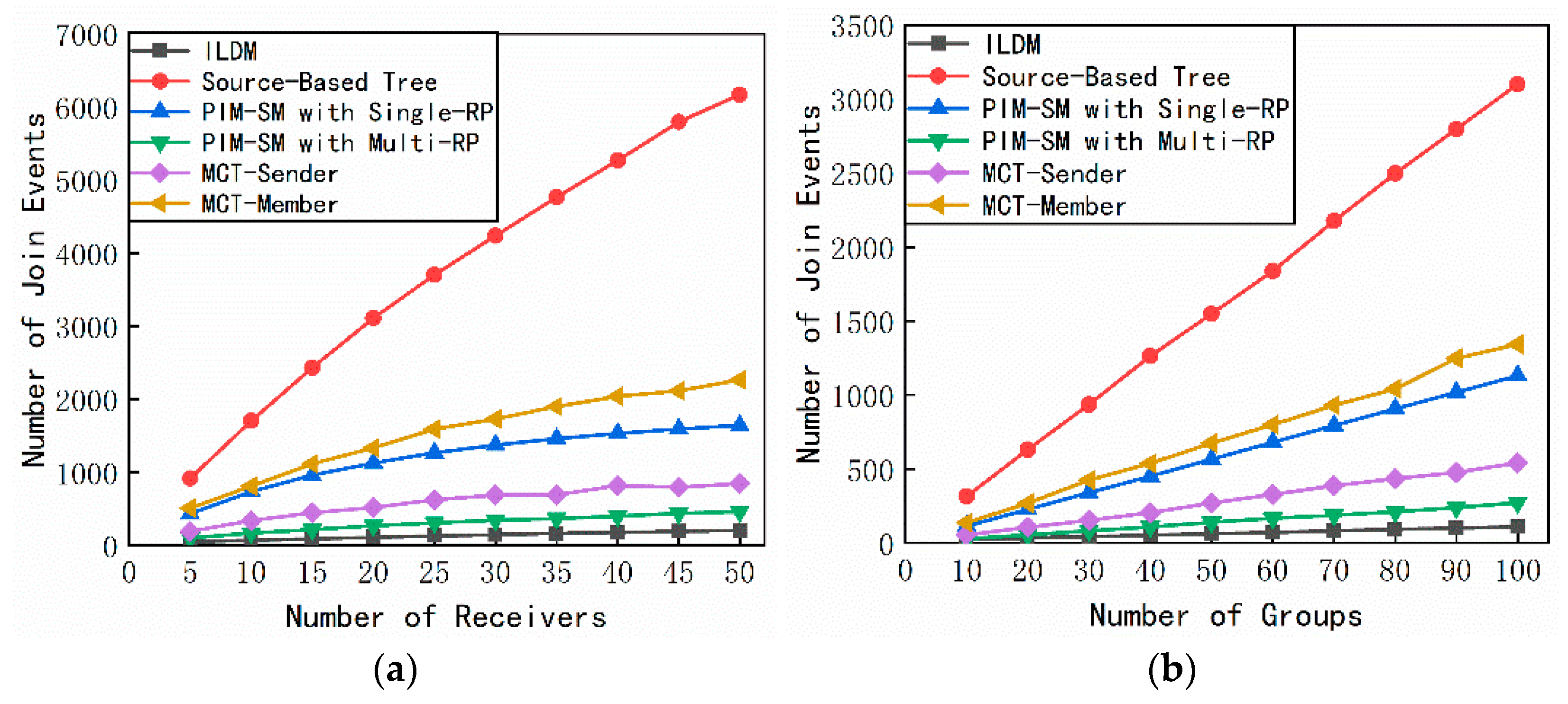
4.2. Number of Join Requests

Our second set of experiments measured the number of join requests, which is the maximum number of join requests processed by a router. We counted the number of join requests processed by each router and got the maximum of these values. In the experiment shown in Figure 7a, the number of routers, load threshold, number of groups, and number of sources per group were set to 100, 5, 100, and 20. In the experiment shown in Figure 7b, the number of routers, load threshold, number of sources per group, and number of receivers per group were set to 100, 5, 20, and 20.
From Figure 7a,b, we can find that the maximum number of join requests handled by a router in ILDM was less than other multicast methods. Moreover, as the number of receivers or groups increased, the maximum number of join requests handled by a router in ILDM grew much slower than in other methods. This was because we used a path state-aware multicast tree node selection mechanism to select an MTN with the best path state for each receiver to join. The load of the routers on the path between the receiver and the MTN was low. Although the maximum number of join requests handled by a router in PIM-SM with multi RP was close to that in ILDM, from the results of other experiments, we found that ILDM has advantages over PIM-SM with multi RP in terms of core load, link load, traffic concentration and routing state.

4.3. Link Load

Our third set of experiments measured the link load. We calculated the number of flows traversing through each link. Due to encapsulation, a given link may be traversed multiple times by a single flow, and these events were counted. We used the load of the link with the largest load among all links to evaluate the performance in terms of link load. We used a topology with 100 routers and set the load threshold to five in this set of experiments. In the experiment shown in Figure 8a, the number of groups and number of receivers were set to 100 and 20. In the experiment shown in Figure 8b, the number of groups and the number of sources per group were set to 100 and 20. In the experiment shown in Figure 8c, the number of sources and the number of receivers were set to 20 and 20.
From Figure 8a–c, we can find that as the number of sources, receivers, or groups increased, the maximum link load in all multicast methods increased. However, the maximum link load in ILDM is less than that in other multicast methods. First, in ILDM, we use a dynamic core selection mechanism to dynamically allocate a low-load core to each multicast group, thereby distributing the traffic sent by the multicast sources to different cores. Then, we used a path state-aware multicast tree node selection mechanism to select the MTN with the best path state for each receiver to join. In this way, the multicast traffic is distributed to low-load links. However, other multicast methods always use the shortest path between the source or core and each receiver to construct the multicast tree without considering the link state. This results in many multicast flows passing through the same link and underutilizing the low-load links. In addition, in PIM-SM and MCT, all multicast traffic needs to be aggregated to one or several cores, which will cause traffic aggregation on these cores. Although the maximum link load in SBT was close to that in ILDM, from the results of other experiments, we can find that ILDM has advantages over SBT in terms of the number of join requests, traffic concentration, and routing state.

4.4. Traffic Concentration

Our fourth set of experiments measured traffic concentration. We used the standard deviation and concentration ratio of the load of all links to evaluate traffic concentration. The concentration ratio was the ratio of the maximum load of all links to the average load of all links. We used a topology with 100 routers and set the load threshold to five in this set of experiments. In the experiment shown in Figure 9a and Figure 10a, the number of groups and number of receivers were set to 100 and 20. In the experiment shown in Figure 9b and Figure 10b, the number of groups and the number of sources per group were set to 100 and 20. In the experiment shown in Figure 9c and Figure 10c, the number of sources and the number of receivers were set to 20 and 20.

4.5. Routing State

Our fifth set of experiments measured the routing state, which was defined as the maximum number of multicast routing entries stored per router. We used a topology with 50 routers and set the load threshold to five in this set of experiments. The experimental results are shown in Figure 11a–c. In the experiment shown in Figure 11a, the number of groups and number of receivers were set to 100 and 20. In the experiment shown in Figure 11b, the number of groups and the number of sources per group were set to 100 and 20. In the experiment shown in Figure 11c, the number of sources and the number of receivers were set to 20 and 20.
We found that the amount of multicast routing states per router in our method was close to that in MCT-Sender and is smaller than other methods. Moreover, the number of multicast routing states in SBT was much greater than that in other multicast methods. This is because, in the core-based multicast methods, all sources in each group share a multicast entry, while in SBT each source requires a multicast entry. Meanwhile, in other core-based multicast methods, the multicast flow is transmitted according to the shortest path between the core and the receiver without considering the problem of traffic balance. This will cause many multicast flows to pass through the same router, resulting in more multicast entries in the router. In ILDM, since the multicast flows are directed to the low-load links, the number of flow states that each router needs to maintain is reduced. Although the routing state in MCT-Sender is close to that in ILDM, ILDM has advantages over MCT-Sender in terms of core load, the number of join requests, link load, and traffic concentration.

5. Conclusions

In this paper, we proposed the multicast approach named ILDM to avoid core overload and achieve traffic load balancing. In ILDM, each multicast service is identified by a globally unique MSEID, and the mapping between the MSEID and the NAs of multicast tree nodes is stored in the NRS. To avoid core overload and reduce traffic aggregation on the core, we design dynamic core management and selection mechanism. Routers can register with NRS as candidate cores. NRS maintains the state of each candidate core and dynamically assigns a low-load core to each multicast service. Furthermore, we designed a path state-aware multicast tree node selection mechanism. The multicast tree node with the best path state is selected for each receiver to join the multicast service. By using low-load links more efficiently, traffic aggregation is alleviated. The simulation results showed that our multicast approach has the following advantages compared with other ST-based multicast approaches: (1) it reduced the load of each core and achieve load balancing; (2) it reduced the number of join requests that each router needs to handle; (3) it reduced link load and avoid traffic aggregation; and (4) it reduced the number of multicast states per router.
In future work, we will consider the location of the core, sources, and receivers when selecting the core for each multicast service. We will also study the impact of node failures, link failures, and packet loss on multicast communications and improve the reliability of ILDM to meet the high-reliability requirements in some scenarios (e.g., Vehicle Networking). Moreover, we will evaluate our proposed multicast approach on a testbed.

Author Contributions

Conceptualization, B.L. and J.W.; methodology, B.L. and J.W.; software, B.L.; writing—original draft preparation, B.L.; writing—review and editing, B.L. and J.W.; supervision, J.W.; project administration, J.W.; funding acquisition, J.W. All authors have read and agreed to the published version of the manuscript.

Funding

This work was funded by the Strategic Leadership Project of Chinese Academy of Sciences: SEANET Technology Standardization Research System Development (Project No. XDC02070100).

Institutional Review Board Statement

Not applicable.

Informed Consent Statement

Not applicable.

Data Availability Statement

Data sharing not applicable.

Conflicts of Interest

The authors declare no conflict of interest.

References

  1. Al-Fuqaha, A.; Guizani, M.; Mohammadi, M.; Aledhari, M.; Ayyash, M. Internet of Things: A Survey on Enabling Technologies, Protocols, and Applications. IEEE Commun. Surv. Tutor. 2015, 17, 2347–2376. [Google Scholar] [CrossRef]
  2. Wang, G.; Baccelli, E.; Zhang, Y.; Burke, J.; Grieco, L.; Ravindran, R.; Raychadhuri, D. ICN based Architecture for IoT—Requirements and Challenges. Acm Sigmetrics Perform. Eval. Rev. 2015, 40, 65–76. [Google Scholar]
  3. Huang, J.; Duan, Q.; Zhao, Y.; Zheng, Z.; Wang, W. Multicast Routing for Multimedia Communications in the Internet of Things. IEEE Internet Things J. 2016, 4, 215–224. [Google Scholar] [CrossRef]
  4. Tsoukaneri, G.; Condoluci, M.; Mahmoodi, T.; Dohler, M.; Marina, M.K. Group Communications in Narrowband-IoT: Architecture, Procedures, and Evaluation. IEEE Internet Things J. 2018, 5, 1539–1549. [Google Scholar] [CrossRef] [Green Version]
  5. Cisco, V. Cisco Visual Networking Index: Forecast and Trends 2017–2022. White Pap. 2018, 1, 1. [Google Scholar]
  6. Baddi, Y.; Kettani, E.C.E. VNS-RP Algorithm for RP Selection in Multicast Routing Protocol PIM-SM. In Proceedings of the International Conference on Multimedia Computing and Systems, Tangier, Morocco, 10–12 May 2012. [Google Scholar]
  7. Wang, L.-X.; Cao, W.C. A Load Distribution Algorithm Based on an Ant Colony for Multi-Source Multicast Networks. J. Shandong Univ. (Nat. Sci.) 2011, 46, 28–32. [Google Scholar]
  8. Kumar, S.; Radoslavov, P.; Thaler, D.; Alaettino, L.C.; Estrin, D.; Handley, M. The MASC/BGMP Architecture for Inter-Domain Multicast Routing. In Proceedings of the ACM SIGCOMM ′98 Conference on Applications, Technologies, Architectures, and Protocols for Computer Communication, Vancouver, BC, Canada, 31 August–4 September 1998. [Google Scholar]
  9. Ahlgren, B.; Dannewitz, C.; Imbrenda, C.; Kutscher, D.; Ohlman, B. A survey of Information-Centric Networking. IEEE Commun. Mag. Artic. News Events Interest Commun. Eng. 2012, 50, 26–36. [Google Scholar] [CrossRef]
  10. Xylomenos, G.; Ververidis, C.N.; Siris, V.A.; Fotiou, N.; Tsilopoulos, C.; Vasilakos, X.; Katsaros, K.V.; Polyzos, G.C. A Survey of Information-Centric Networking Research. Commun. Surv. Tutor. IEEE 2014, 16, 1024–1049. [Google Scholar] [CrossRef]
  11. Jiang, X.; Bi, J.; Nan, G.; Li, Z. A Survey on Information-Centric Networking: Rationales, Designs and Debates. China Commun. 2015, 12, 1–12. [Google Scholar] [CrossRef]
  12. Jacobson, V.; Smetters, D.K.; Thornton, J.D.; Plass, M.F.; Briggs, N.H.; Braynard, R.L. Networking Named Nontent. Proc. Acm Conex. 2009, 1–12. [Google Scholar] [CrossRef]
  13. Zhang, L.; Afanasyev, A.; Burke, J.; Jacobson, V.; Papadopoulos, C.; Claffy, K.; Wang, L.; Crowley, P.; Zhang, B. Named Data Networking. Acm Sigcomm. Comput. Commun. Rev. 2014, 44, 66–73. [Google Scholar] [CrossRef]
  14. Saxena, D.; Raychoudhury, V.; Suri, N.; Becker, C.; Cao, J. Named Data Networking: A survey. Comput. Rev. 2016, 19, 15–55. [Google Scholar] [CrossRef] [Green Version]
  15. Fotiou, N.; Nikander, P.; Trossen, D.; Polyzos, G.C. Developing Information Networking Further: From PSIRP to PURSUIT. In Proceedings of the International Conference on Broadband Communications, Networks and Systems, Athens, Greece, 25–27 October 2010; pp. 11–13. [Google Scholar] [CrossRef] [Green Version]
  16. Koponen, T.; Chawla, M.; Chun, B.G.; Ermolinskiy, A.; Stoica, I. A Data-Oriented (and Beyond) Network Architecture. ACM SIGCOMM Comput. Commun. Rev. 2007, 181–192. [Google Scholar] [CrossRef]
  17. Dannewitz, C.; Kutscher, D.; Ohlman, B.R.; Farrell, S.; Ahlgren, B.; Karl, H. Network of Information (NetInf)—An Information-Centric Networking Architecture. Comput. Commun. 2013, 36, 721–735. [Google Scholar] [CrossRef]
  18. Venkataramani, A.; Kurose, J.F.; Banerjee, S.; Raychaudhuri, D.; Nagaraja, K.; Mao, Z.M. MobilityFirst: A Mobility-Centric and Trustworthy Internet Architecture. ACM Sigcomm. Comput. Commun. Rev. 2014, 44, 74–80. [Google Scholar] [CrossRef]
  19. Bari, M.F.; Chowdhury, S.R.; Ahmed, R.; Boutaba, R.; Mathieu, B. A Survey of Naming and Routing in Information-Centric Networks. IEEE Commun. Mag. 2012, 50, 44–53. [Google Scholar] [CrossRef]
  20. Liao, Y.; Sheng, Y.; Wang, J. A Survey on the Name Resolution Technologies in Information Centric Networking. J. Netw. New Media 2020, 9, 1–9. [Google Scholar]
  21. Zeng, L.; Ni, H.; Han, R. An Incrementally Deployable IP-Compatible-Information-Centric Networking Hierarchical Cache System. Appl. Sci. 2020, 10, 6228. [Google Scholar] [CrossRef]
  22. Lt, J.M.; Com, G.J. Multicast Extensions to OSPF. Ietf RFC 1994, 11, 82–89. [Google Scholar]
  23. Lt, T.P.; Com, G.P. Distance Vector Multicast Routing Protocol. IEEE Commun. Soc. 1988, 33, 10. [Google Scholar]
  24. Adams, A.; Nicholas, J.; Siadak, W. Protocol Independent Multicast-Dense Mode (PIM-DM): Protocol Specification (Revised). RFC 3973. Available online: https://www.hjp.at/doc/rfc/rfc3973.html (accessed on 8 January 2021).
  25. Bhattacharyya, S.; Diot, C.; Giuliano, L.; Rockell, R.; Meylor, J. An Overview of Source-Specific Multicast (SSM). RFC 3569. Available online: https://www.hjp.at/doc/rfc/rfc3569.html (accessed on 8 January 2021).
  26. Ballardie, T.; Francis, P.; Crowcroft, J. Core Based Trees (CBT). Acm Sigcomm. Comput. Commun. Rev. 1993, 23, 85–95. [Google Scholar] [CrossRef]
  27. Estrin, D.; Farinacci, D.; Helmy, A.; Thaler, D.; Deering, S.; Handley, M.; Jacobson, V.; Liu, C.-G.; Sharma, P.; Wei, L. Protocol Independent Multicast-Sparse Mode (PIM-SM): Protocol Specification. RFC 2362. Available online: https://dl.acm.org/doi/pdf/10.17487/RFC2362 (accessed on 8 January 2021).
  28. Shields, C.; Garcia-Luna-Aceves, J.J. The ordered Core Based Tree Protocol. In Proceedings of the INFOCOM ‘97. Sixteenth Annual Joint Conference of the IEEE Computer and Communications Societies, Kobe, Japan, 7–11 April 1997. [Google Scholar]
  29. Zappala, D.; Fabbri, A.; Lo, V. An Evaluation of Shared Multicast Trees with Multiple Active Cores. Telecommun. Syst. 2002, 19, 461–479. [Google Scholar] [CrossRef]
  30. Kabat, M.R.; Sahoo, S.P. Adaptive Tabu Search Algorithm for RP Selection in Protocol Independent Multicast—Sparse Mode. In Proceedings of the Information and Communication Technologies (WICT), 2011 World Congress, Piscataway, NJ, USA, 11–14 December 2011. [Google Scholar]
  31. Baddi, Y.; Kettani, E.C.E. D2V-VNS-RPS: Delay and Delay Variation Constrained Algorithm Based on Variable Neighborhood Search Algorithm for RP Selection Problem in PIM-SM Protocol. In Proceedings of the IEEE International Conference on Complex Systems (ICCS), Agadir, Morocco, 5–6 November 2012. [Google Scholar]
  32. Sinha, K.; Gupta, B.; Rahimi, S.; Bhattacharya, A. Candidate Core Selection for Load-Balanced Multicore Shared Tree Multicasting. In Proceedings of the 3rd International Conference on Recent Advances in Information Technology (RAIT), Dhanbad, India, 3–5 March 2016; pp. 35–40. [Google Scholar]
  33. Lee, D.L.; Youn, C.H.; Jeong, S.J. RP Reselection Scheme for Real-Time Applications in Delay-Constrained Multicast Networks. In Proceedings of the IEEE International Conference on Communications, New York, NY, USA, 28 April–2 May 2002. [Google Scholar]
  34. Ren, C.; Wang, S.; Ren, J.; Wang, X. Traffic Engineering and Manageability for Multicast Traffic in Hybrid SDN. KSII Trans. Internet Inf. Syst. 2018, 12. [Google Scholar]
  35. Liu, H.; Azhandeh, K.; de Foy, X.; Gazda, R. Comparative Study of Name Resolution and Routing Mechanisms in Information-Centric Networks. Digit. Commun. Netw. 2019, 5, 69–75. [Google Scholar] [CrossRef]
  36. D’Ambrosio, M.; Dannewitz, C.; Karl, H.; Vercellone, V. MDHT: A Hierarchical Name Resolution Service for Information-Centric Networks. In Proceedings of the ACM SIGCOMM Workshop on Information-Centric Networking, Toronto, ON, Canada, 15–19 August 2011. [Google Scholar]
  37. Dannewitz, C.; D’Ambrosio, M.; Vercellone, V. Hierarchical DHT-Based Name Resolution for Information-Centric Networks; Elsevier, B.V., Ed.; Elsevier Science Publishers: Berlin/Heidelberg, Germany, 2013. [Google Scholar]
  38. Liao, Y.; Sheng, Y.; Wang, J. A Temporally Hierarchical Deployment Architecture for an Enhanced Name Resolution System. Appl. Sci. 2019, 9, 2891. [Google Scholar] [CrossRef] [Green Version]
  39. Mukherjee, S.; Bronzino, F.; Srinivasan, S.; Chen, J.; Raychaudhuri, D. Achieving Scalable Push Multicast Services Using Global Name Resolution. In Proceedings of the IEEE Global Communications Conference (GLOBECOM), Washington, DC, USA, 4–8 December 2016. [Google Scholar]
  40. Yang, B.; Chen, X.; Xie, J.; Li, S.; Yang, J. Multicast Design for the MobilityFirst Future Internet Architecture. Proceedings of International Conference on Computing, Networking and Communications (ICNC), Honolulu, HI, USA, 18–21 February 2019. [Google Scholar]
  41. Medina, A.; Lakhina, A.; Matta, I.; Byers, J. BRITE: An Approach to Universal Topology Generation. In Proceedings of the International Workshop on Modeling, Cincinnati, OH, USA, 15–18 August 2001. [Google Scholar]
Figure 1. The architecture model of the ILDM.
Applsci 11 00578 g001
Figure 2. The example of core discovery and selection process. (a) The core discovery and selection process of S1 and S2; (b) the core discovery and selection process of S3.
Applsci 11 00578 g002
Figure 3. The format of messages. (a) The format of the path state detection message; (b) the format of the detection response message.
Applsci 11 00578 g003
Figure 4. The example of the multicast tree node selection process.
Applsci 11 00578 g004
Figure 5. The use-cases of PIM-SM and ILDM. (a) The use-case of PIM-SM; (b) the use case of ILDM.
Applsci 11 00578 g005
Figure 6. The comparison of maximum core load. (a) The variation trends of maximum core load with the different number of groups in ILDM; (b) the variation trends of maximum core load with the different number of sources and load threshold in ILDM; (c) the comparison of the maximum core load in different methods with the different number of groups; (d) the comparison of the maximum core load in different methods with the different number of routers.
Applsci 11 00578 g006
Figure 7. The comparison of the maximum number of join requests. (a) The variation trends of the maximum number of join requests with a different number of receivers; (b) The variation trends of the maximum number of join requests with a different number of groups.
Applsci 11 00578 g007
Figure 8. The comparison of maximum link load. (a) The variation trends of maximum link load with a different number of sources; (b) the variation trends of maximum link load with a different number of receivers; (c) The variation trends of maximum link load with a different number of groups.
Applsci 11 00578 g008
Figure 9. The comparison of link loads’ standard deviation. (a) The variation trends of link loads’ standard deviation with a different number of sources; (b) the variation trends of link loads’ standard deviation with a different number of receivers; (c) The variation trends of link loads’ standard deviation with a different number of groups.
Applsci 11 00578 g009
Figure 10. The comparison of concentration ratio. (a) The variation trends of concentration ratio with a different number of sources; (b) the variation trends of concentration ratio with a different number of receivers; (c) The variation trends of concentration ratio with a different number of groups.
Applsci 11 00578 g010
Figure 11. The comparison of the maximum number of routing states. (a) The variation trends of the maximum number of routing states with a different number of sources; (b) The variation trends of the maximum number of routing states with a different number of receivers; (c) The variation trends of the maximum number of routing states with a different number of groups.
Applsci 11 00578 g011
Table 1. The meaning of symbols in this part.
SymbolMeaningSymbolMeaning
L t h the load threshold of each router N C the number of used cores
N R the number of routers L i the load of the i-th core
N G the number of groups L m a x the load of the core with the largest load
N S the number of sources per group
Table 2. The meaning of symbols in this part.
SymbolMeaningSymbolMeaning
{ M T N }the list of multicast tree nodes L a v r o p t i the average link load of M T N o p t i
M T N o p t i the optimal multicast tree node L m a x the maximum link load of the M T N
L m a x o p t i the maximum link load of M T N o p t i L a v r the average link load of the M T N
Table 3. Evaluation setting.
ParameterValue
CPUs8 Intel(R) Core (TM) i7-6700 CPU @ 3.40GHz
Memory16 GB
Operating systemWindow10
TopologyWaxman, α = 0.15 ,   β = 0.2 ,   m   degree = 4
Node placementRandom
Number of routers5, 10, 15, 20, 25, 30, 35, 40, 45, 50, 100
Number   of   sources   per   group 5, 10, 15, 20, 25, 30, 35, 40, 45, 50
Number of groups5, 10, 15, 20, 25, 30, 35, 40, 45, 50, 55, 60, 65, 70, 75, 80, 85, 90, 95, 100, 120, 140, 160, 180, 200
Publisher’s Note: MDPI stays neutral with regard to jurisdictional claims in published maps and institutional affiliations.

