Article

Position Control Based on Add-on-Type Iterative Learning Control with Nonlinear Controller for Permanent-Magnet Stepper Motors

1
Department of Information and Telecommunication Engineering, Gangneung-Wonju National University, Wonju-si, Gangwon-do 26403, Korea
2
School of Energy Systems Engineering, Chung-Ang University, Seoul 06974, Korea
*
Author to whom correspondence should be addressed.
Appl. Sci. 2021, 11(2), 587; https://doi.org/10.3390/app11020587
Submission received: 18 December 2020 / Revised: 4 January 2021 / Accepted: 5 January 2021 / Published: 8 January 2021

Abstract

:
In this paper, a current-error-based iterative learning controller (ILC) with a nonlinear controller is proposed to improve the position-tracking performance in permanent-magnet (PM) stepper motors. Our proposed method comprises a current-error-based ILC for mechanical dynamics and a nonlinear controller for current dynamics. A nonlinear controller using a variable structure is designed to obtain the field-oriented control. This nonlinear controller can cause the PM stepper motor become a single-input single-output linear system after finite time. The add-on-type ILC with proportional–integral control is designed to improve the position-tracking performance as the systems repeatedly perform the same operation. To increase the rate of error convergence, the current-error-based ILC is designed using the plant inversion method. The condition that the error converges to zero is mathematically derived. Thus, the proposed method can reduce the position-tracking error as the systems repeatedly perform the same operation. Furthermore, the proposed method can be easily plugged into the pre-designed controller. The performance of our proposed method was evaluated via simulations. In simulations, it is observed that the proposed method reduces the position-tracking error compared to the previous methods.

1. Introduction

Permanent-magnet (PM) stepper motors have been widely used for positioning applications owing to their power density, high efficiency, durability, high torque-to-inertia ratio, and the absence of rotor winding in industrial applications such as antennae, lasers, video cameras, rotary tables, wrapping machines, and robots [1,2]. In industrial applications, microstepping is widely used with a closed-loop in current loops; thus, proportional–integral (PI) controllers are embedded in the motor drives for current regulation [3]. However, as the microstepping-based control method with the current controller only considered the electrical dynamics in the PM stepper motor, a position-tracking error during the nonzero velocity period cannot be avoided [4].
With the increase in power and decrease in the cost of embedded processors in recent years, driving and control systems for PM stepper motors have become increasingly sophisticated. Thus, for positioning applications, the PM stepper motor can be substituted for expensive servomotors, such as PM synchronous motors, as a cheaper replacement for closed-loop operation. Various control methods have been developed to improve the position/velocity control performance in PM stepper motors [5,6,7,8,9,10,11,12]. A model-based control law was proposed to improve position control in [5]. A simple and effective position and velocity controller was proposed for field-weakening control (FWC) of PM stepper motors [6]. In [7], a sensorless controller was proposed for the velocity control of PM stepper motors. In [8], torque modulation-based microstepping was developed to realize field-oriented control (FOC) and FWC without direct-quadrature (DQ) transformation, and an integrator reset control was designed in [9] to improve transient response with position control of the PM stepper motor. An enhanced nonlinear damping controller was proposed to reduce the position-tracking error [10]. Furthermore, a nonlinear H 2 control with varying linear parameters was developed to optimize control performance [11]. In [12], an effective closed-loop control comprising motor parameter identification, closed-loop current control, closed-loop position control, and damping control was proposed. A model predictive controller was designed for external periodic disturbance attenuation in PM stepper motors [13]. Robust speed control using two-degrees-of-freedom control was developed to guarantee the exponential stability for PM synchronous motors(PMSMs) [14]. A discrete-time fast terminal sliding mode control was developed to improve the position tracking performance in PM linear stepper motors [15]. In [16], a finite-time control algorithm was designed to improve PMSM system’s dynamical performance and disturbance rejection ability. An internal model principle-based controller was proposed to reduce sideband harmonics for PM stepper motors with low-switching-frequency inverters in [17].
PM stepper motors are usually operated with a repetitive desired position trajectory. This case was not considered in the previous methods, although previous methods improved the position/velocity performance. Iterative learning controllers (ILCs) have been applied to improve the performance of systems that repeat periodic movements [18], such as hard disk drives and scanners [19,20,21]. In previous methods, past-error-based ILCs were used; thus, the convergence of the tracking errors was slow. Several ILC methods were developed for the PM stepper motors and the PMSMs [22,23]. However, the current dynamics were not considered in those methods.
In this paper, a current-error-based ILC with a nonlinear controller is proposed to improve the position-tracking performance of the PM stepper motors. The proposed method consists of the current-error-based ILC for mechanical dynamics and a nonlinear controller for current dynamics. A nonlinear controller using a variable structure is designed to obtain FOC. This nonlinear controller can make the PM stepper motor become a single-input single-output (SISO) linear system after a finite time. The add-on-type ILC with PI is designed to improve the position-tracking performance as the systems perform the same operation repeatedly. To fasten the error convergence, the current-error-based ILC is designed using the plant inversion method. The condition that the error converges to zero is mathematically derived. Thus, the proposed method can reduce the position-tracking error as the systems repeatedly perform the same operation. Furthermore, the proposed method can be easily plugged into the pre-designed controller. The performance of our proposed method was evaluated via simulations. In simulations, it is observed that the proposed method reduces the position-tracking error compared to the previous methods.
The remainder of this paper is organized as follows. In Section 2, a mathematical model of the PM stepper motor is presented, and the controller design is developed. Simulation results are discussed in Section 3, and concluding statements are presented in Section 4.

2. Controller Design

The PM stepper motor comprises a slotted stator with two phases and a permanent-magnet rotors having both north and south poles. Its detailed information can be found in [2,24,25]. With DQ transformation, the mathematical model of the PM stepper motor can be represented in state space form as [2,5,24,25]
θ ˙ = ω ω ˙ = 1 J ( B ω + K m i q + d ) i ˙ d = 1 L ( v d R i d + N r L ω i q ) i ˙ q = 1 L ( v q R i q N r L ω i d K m ω ) ,
where v d , v q and i d , i d denote the direct and quadrature voltages and the direct and quadrature currents, respectively, ω is the rotor (angular) speed, θ is the rotor (angular) position, B is the viscous friction coefficient, J is the inertia of the motor, K m is the motor torque constant, R is the resistance of the phase winding, L is the inductance of the phase winding, N r is the number of the rotor teeth, and d is the periodic disturbance.
The proposed method comprises an ILC and a nonlinear controller. First, a nonlinear controller is designed for the finite convergence of the current tracking errors to zeros. Subsequently, the ILC is designed for position tracking.

2.1. Nonlinear Controller for Current Dynamics

The current tracking errors are defined as
e d = e d d e d e q = e q d e q ,
where e d d is the desired direct current and is set to 0 for the FOC and e q d is the desired quadrature current that is yet to be defined. The current tracking error dynamics are
e ˙ d = e ˙ d d 1 L ( v d R i d + N r L ω i q ) e ˙ q = e ˙ q d 1 L ( v q R i q N r L ω i d K m ω )
Theorem 1.
Suppose the current tracking error dynamics (3). If the electrical controller (4) is applied to the current tracking error dynamics (3)
v d = L k d e d + L ρ d sgn ( e d ) + R i d N r L ω i q + L e ˙ d d v q = L k q e q + L ρ q sgn ( e q ) + R i q + N r L ω i d + K m ω + L e ˙ q d
where k d , k q , and ρ d , ρ q are control gains and positive constants, respectively, then the current tracking errors e d d and e q d converge to zeros in finite time.
Proof. 
Lyapunov candidate function V e is defined as
V e = 1 2 e d 2 + 1 2 e q 2 .
The derivative of V e is
V ˙ e = e d ( e ˙ d d 1 L ( v d R i d + N r L ω i q ) ) + e q ( e ˙ q d 1 L ( v q R i q N r L ω i d K m ω ) ) .
Using the electrical controller (4), V ˙ e becomes
V ˙ e = k d e d 2 k q e q 2 ρ d sgn ( e d ) ρ q sgn ( e q ) .
Thus, the current tracking errors e d d and e q d converge to zero in finite time. □
After the current tracking errors e d d and e q d converge to zeros in finite time, the PM stepper motor model (8) becomes a second-order model as
θ ˙ = ω ω ˙ = 1 J ( B ω + K m i q d + d ) .

2.2. Add-on-Type ILC for Mechanical Dynamics

The PM stepper motor model (1) with the electrical controller (4) is shown in Figure 1. In Figure 1, the transfer function P ( s ) from i q to θ is defined as
Θ ( s ) = K m s ( J s + B ) P ( s ) ( I q d ( s ) + D ( s ) )
where Θ ( s ) , I q d ( s ) , and D ( s ) are the Laplace transforms of θ , i q d , and d, respectively. For the position tracking control in (9), the PI controller C ( s ) is designed as
i q d = C ( s ) e θ = ( k p + k i 1 s ) e θ ,
where e θ = θ d θ is the position tracking error, θ d is the desired position, k p is the proportional gain, k i is the integral gain, and PI controller gains are designed to stabilize the closed-loop system.
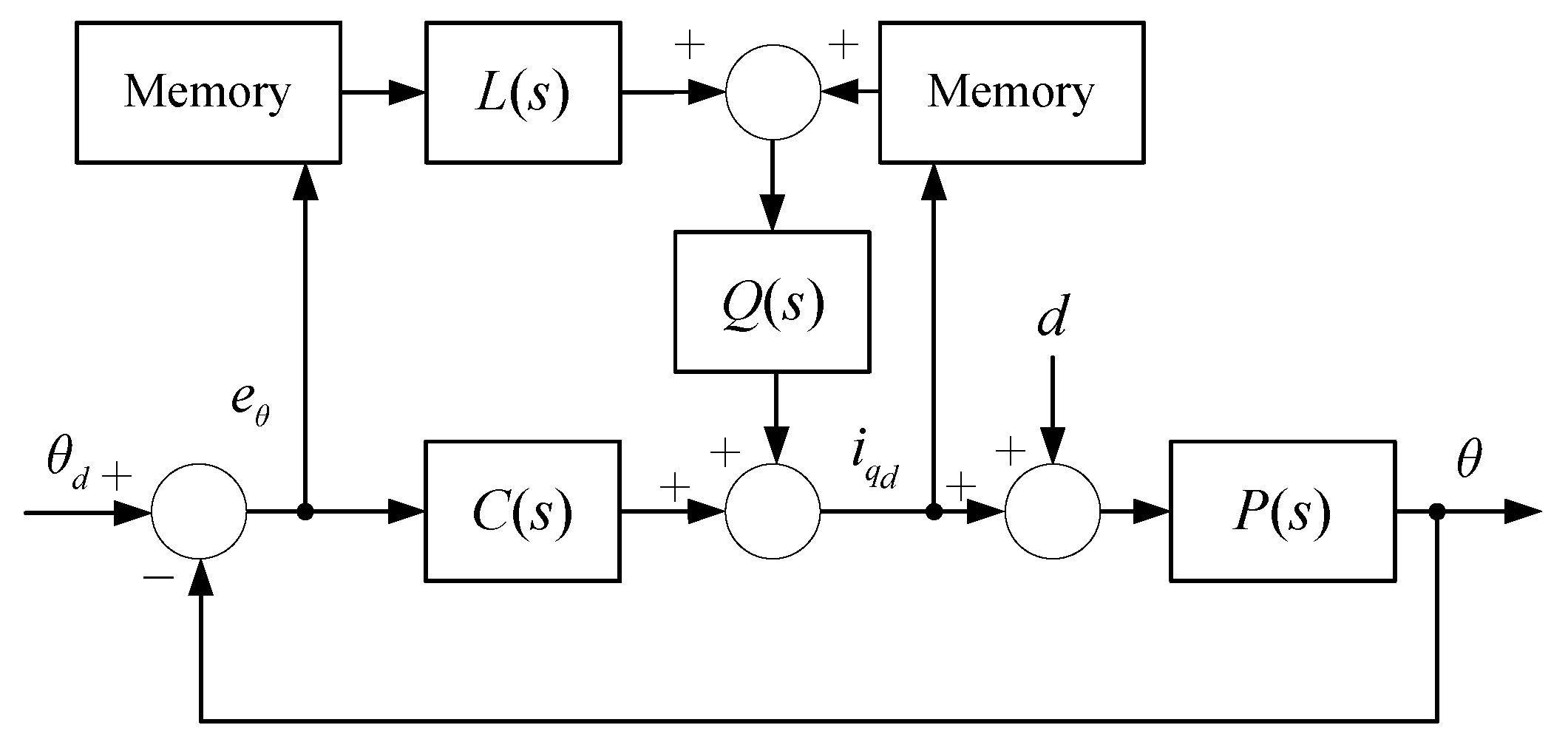
The add-on-type ILC is designed to improve the position tracking performance. For the ILC design, the desired position is the periodic signal used in the systems which operate repeatedly. For a fast convergence rate, the current-error-based ILC is designed as shown in Figure 2. From Figure 2, we have
u j + 1 = Q ( s ) [ u j + L ( s ) e θ j ] + C ( s ) e θ j + 1 ,
where j is the iteration index, L ( s ) is the learning function, and Q ( s ) is the Q-filter.
Theorem 2.
Suppose that the ILC (11) is applied to P ( s ) (9) with the condition
( ( 1 + C P ) 1 Q ( 1 L P ) ) < 1 .
Then, u j converges to u * = ( 1 + C P ) 1 ( Q L + C ) ( ω d P d ) .
Proof. 
As θ d and d are repetitive signals, θ d and d can be regarded as constant in the view point of the iteration domain. In Figure 2, e θ j = θ d P ( u j + d ) . Thus,
u j + 1 = Q u j + Q L e θ j + C e θ j + 1 = Q u j + Q L ( θ d P ( u j + d ) ) + C ( θ d P ( u j + 1 + d ) ) .
From (13),
u j + 1 = ( 1 + C P ) 1 Q ( 1 L P ) u j + ( 1 + C P ) 1 ( Q L + C ) ( ω d P d )
Therefore if condition (12) is satisfied,
lim j u j = ( 1 + C P ) 1 ( Q L + C ) ( ω d P d ) = u * .
L is designed to satisfy condition (12) via the plant inversion method such that L ( s ) P 1 ( s ) for the operation frequency area. Ideally, if L ( s ) = P 1 ( s ) , the convergence rate ( 1 + C P ) 1 Q ( 1 L P ) in (12) becomes 0. Thus, u j converges to u * in just one iteration.
Theorem 3.
If u j converges to u * and L ( s ) P 1 ( s ) for the operation frequency area, then
e * 2 1 P ( 1 + C P ) 1 ( Q L + C ) 2 ( ω d P d ) 2 .
Proof. 
After u j converges to u * , (14) can be rewritten as
u * = ( 1 + C P ) 1 Q ( 1 L P ) u * + ( 1 + C P ) 1 ( Q L + C ) ( ω d P d ) .
Thus,
u * = ( 1 ( 1 + C P ) 1 Q ( 1 L P ) ) 1 ( 1 + C P ) 1 ( Q L + C ) ( ω d P d ) = ( 1 + C P Q + Q L P ) ( Q L + C ) ( ω d P d ) .
As L is the inverse plant,
u * = ( 1 + C P ) 1 ( Q L + C ) ( ω d P d ) .
The steady state error e * is ω d P ( u * + d ) . Therefore,
e * 2 = ω d P ( u * + d ) 2 = ω d P ( ( I + C P ) 1 ( Q L + C ) ( ω d P d ) + d ) 2 1 P ( 1 + C P ) 1 ( Q L + C ) 2 ( ω d P d ) 2 .
Remark 1.
If Q ( s ) = 1 , L ( s ) = P 1 ( s ) , and the system is asymptotically stable, e * becomes zero as follows:
e * 2 1 P ( 1 + C P ) 1 ( Q L + C ) 2 ( ω d P d ) 2 = 0 .
Generally, Q ( s ) is designed to be in the low-pass filter. Thus, it is guaranteed that Q ( s ) 1 for the bandwidth frequency. The bandwidth of Q ( s ) must be wider than the frequency of the main component of the references.
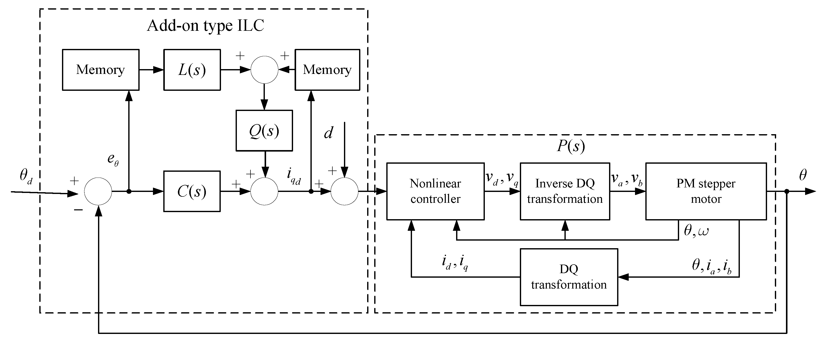
The structure of the proposed method is shown in Figure 3. The nonlinear controller (4) makes the PM stepper motor become a SISO linear system after finite time. Subsequently, the add-on type ILC (11) with PI improves the position tracking performance as the systems repeatedly performed the same operation.

3. Simulation Results

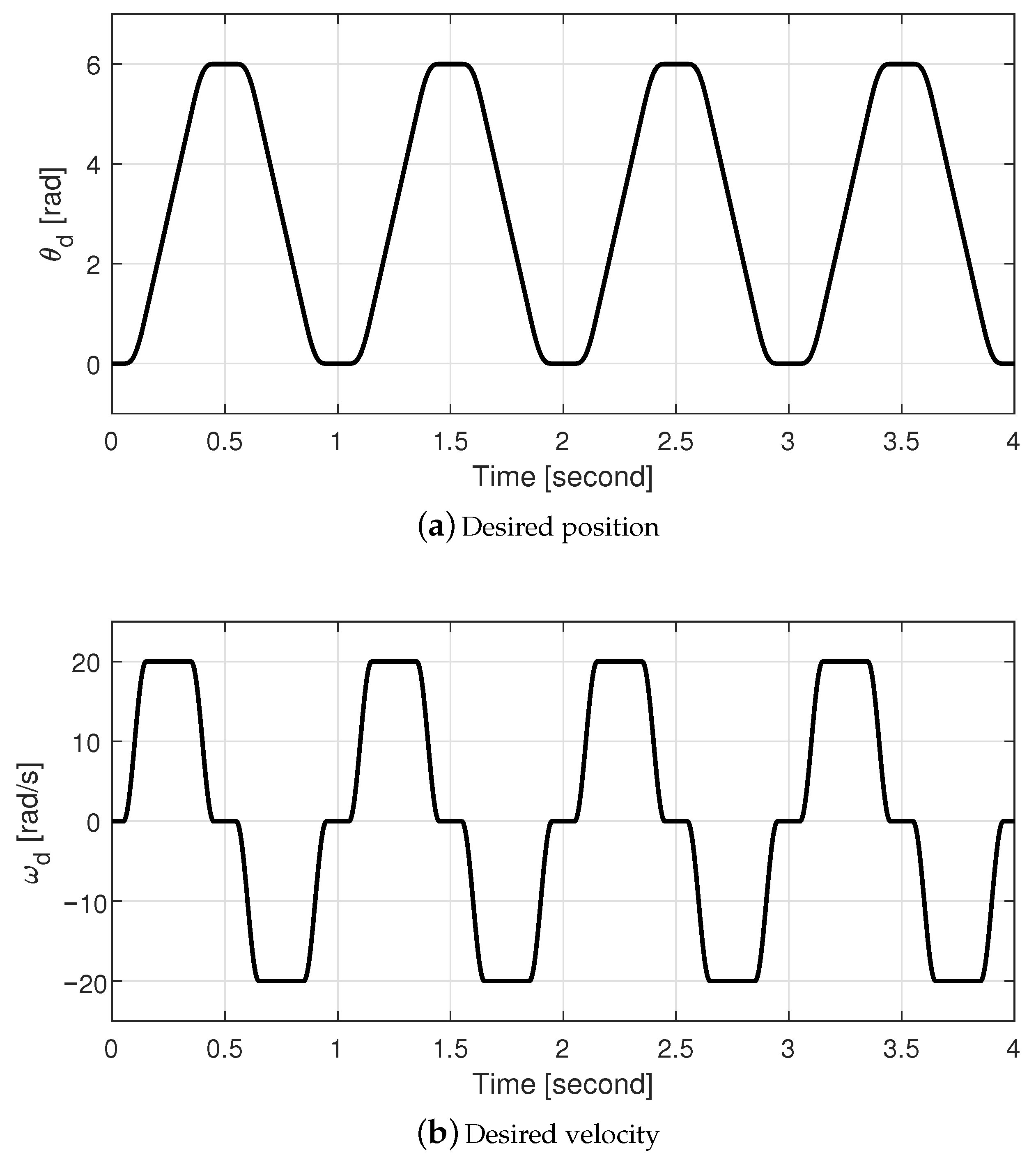
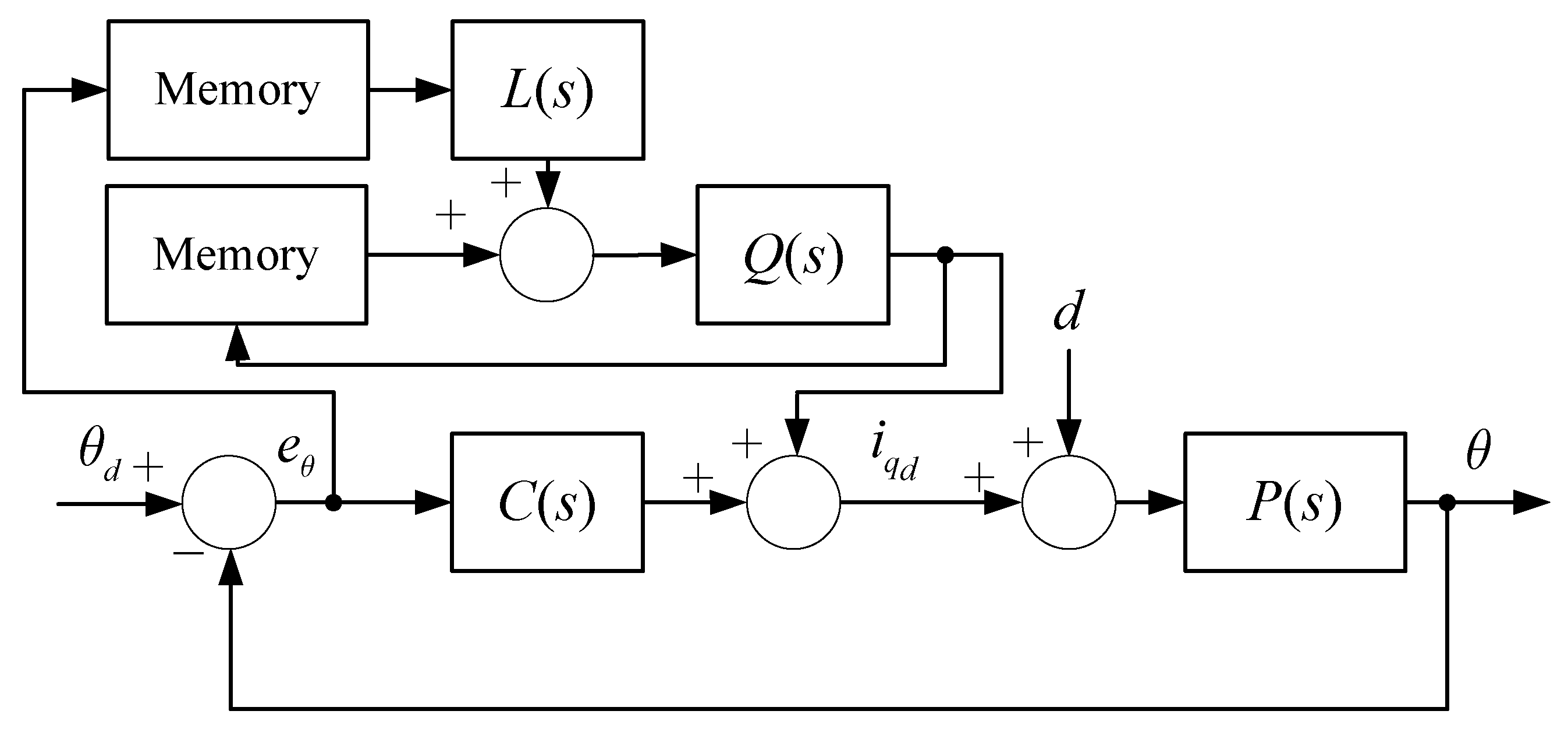
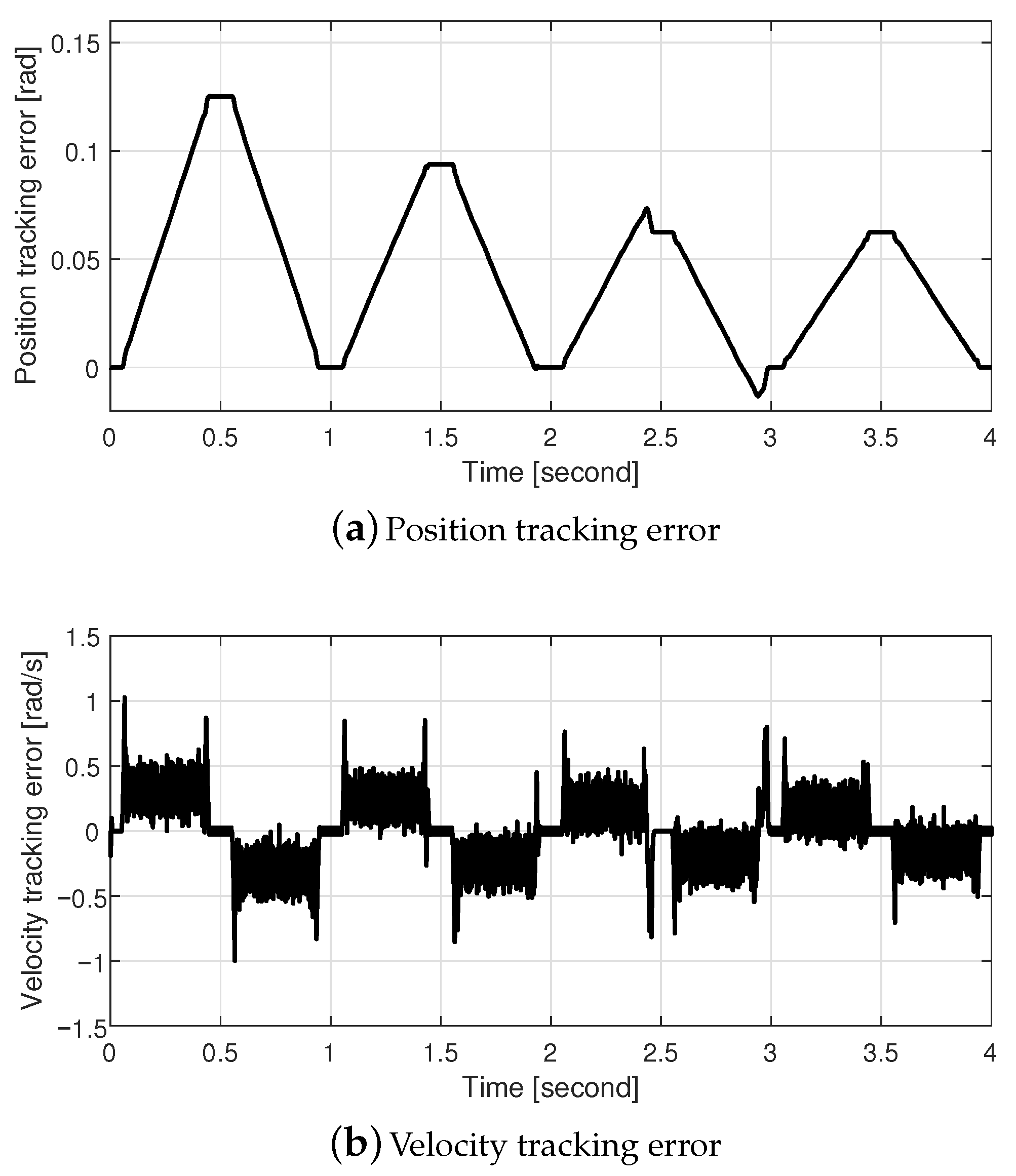
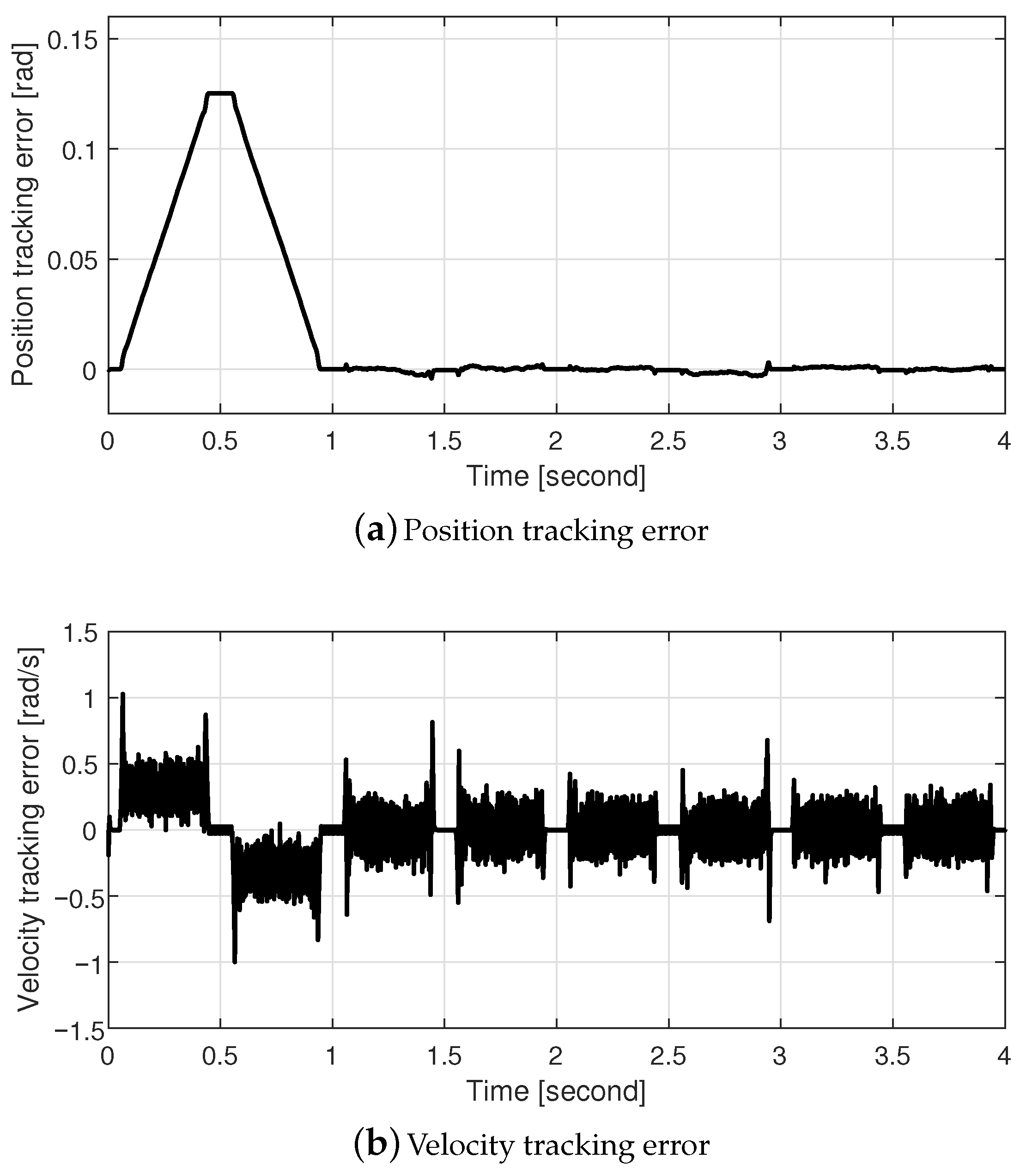
Simulations were performed to evaluate the performance of our proposed method using MATLAB/Simulink as shown in Figure 4a. The PM stepper motor model consisting of SimScape model and PWM drivers as shown in Figure 4b was used. The parameters of the PM stepper motor are listed in Table 1. The PM stepper motor’s parameters listed in Catalog (PK266-01A) [26] were used in the simulations. The nominal and actual parameters may be different, thus, the simulations were tested with the parameter uncertainties, at least, 10 %. The control gains listed in Table 2 were used. L ( s ) and Q ( s ) were designed such that Q ( s ) 1 , L ( s ) P 1 ( s ) for the frequency period (0–100 rad/s). The desired position and velocity shown in Figure 5 were used. To validate the performance of our proposed method, three cases were tested: (1) only PI controller; (2) PI controller with past-error-based ILC, as shown in Figure 6; and (3) a PI controller with current-error-based ILC. For the three cases, the electrical controller (6) was used in the current dynamics. The simulation results for the three cases are shown in Figure 7, Figure 8 and Figure 9. The tracking performance of Case 1 is shown in Figure 7. As only the PI controller was used, both position- and velocity-tracking errors were not reduced from the viewpoint of the iteration. In the steady-state response, the average position and velocity tracking errors of the peak of the desired position were 0.125 rad and ±0.502 rad/s. As the systems repeatedly performed the same operation, these errors were not reduced. On the contrary, in Case 2, both position- and velocity-tracking errors were reduced by the past error-based ILC, as the systems repeatedly performed the same operation. As a result, in the steady-state response, the average position and velocity tracking errors of the peak of the desired position were 0.062 rad and ±0.389 rad/s after three iterations. The convergence rates of the position- and velocity-tracking errors from the viewpoint of the iteration were slow. Both the position- and velocity-tracking errors of Case 3 were rapidly reduced by the current-error-based ILC as compared to Case 2. In the steady-state response, the average position and velocity tracking errors of the peak of the desired position were ±0.002 rad and ±0.275 rad/s after only one iteration.

4. Conclusions

We developed a current-error-based ILC with a nonlinear controller in the PM stepper motors. A nonlinear controller using a variable structure was designed to obtain the FOC and to convert the PM stepper motor into a SISO linear system after finite time. An add-on-type ILC with PI was designed to improve the position-tracking performance as the systems perform the same operation repeatedly. To increase the rate of error convergence, a current-error-based ILC was developed using the plant inversion method. The performance of our proposed method was evaluated via simulations. The simulations showed that our proposed method improved the position-tracking performance as the systems performed the same operation repeatedly. Furthermore, the error convergence rate of the proposed method was faster than that of the past-error-based ILC. The main drawback of the proposed method is the requirement of full state feedback. Thus, in future work, we will study the ILC-based controller using only position feedback.

Author Contributions

S.S. designed the algorithm and developed the simulation; W.K. provided guidance in designing the algorithm; S.S. and W.K. verified the simulation model and results. All authors have read and agreed to the published version of the manuscript.

Funding

This work was supported by the Korean Institute for Advancement of Technology (KIAT) grant funded by the Korean Government (MOTIE) (P0011930, The Establishment Project of the Industry–University Fusion District).

Institutional Review Board Statement

Not applicable.

Informed Consent Statement

Not applicable.

Data Availability Statement

The data presented in this study are available on request from the corresponding author.

Conflicts of Interest

The authors declare that they have no conflict of interest.

References

  1. Kuo, B.C. Theory and Applications of the Step Motors; West Publishing Co.: New York, NY, USA, 1974. [Google Scholar]
  2. Kenjo, T. Stepping Motors and Their Microprocessor Control; Clarendon: Oxford, UK, 1994. [Google Scholar]
  3. Ariasa, A.; Caum, J.; Griñóa, R. Moving towards the maximum speed in stepping motors by means of enlarging the bandwidth of the current controller. Mechatronics 2016, 40, 51–62. [Google Scholar] [CrossRef] [Green Version]
  4. Shin, D.; Kim, W.; Lee, Y.; Chung, C.C. Phase compensated microstepping for permanent magnet stepper motors. IEEE Trans. Ind. Electron. 2013, 60, 5773–5780. [Google Scholar] [CrossRef]
  5. Bodson, M.; Chiasson, J.; Novotnak, R.; Rekowski, R. High-performance nonlinear feedback control of a permanent magnet stepper motor. IEEE Trans. Control Syst. Technol. 1993, 1, 5–14. [Google Scholar] [CrossRef]
  6. Chen, J.-J.; Chin, K.-P. Automatic flux-weakening control of permanent magnet synchronous motors using a reduced-order controller. IEEE Trans. Power Electron. 2000, 15, 881–890. [Google Scholar] [CrossRef]
  7. Lee, J.; Hong, J.; Nam, K.; Ortega, R.; Praly, L.; Astolfi, A. Sensorless control of surface-mount permanent-magnet synchronous motors based on a nonlinear observer. IEEE Trans. Power Electron. 2010, 25, 290–297. [Google Scholar]
  8. Kim, W.; Shin, D.; Chung, C.C. Microstepping with nonlinear torque modulation for permanent magnet stepper motors. IEEE Trans. Control Syst. Technol. 2013, 21, 1971–1979. [Google Scholar]
  9. Shin, D.; Kim, W.; Lee, Y.; Chung, C.C. Nonlinear control with state-dependent reset integrator for a class of singularly perturbed interconnected nonlinear systems. IEEE Trans. Control Syst. Technol. 2017, 25, 1193–1203. [Google Scholar] [CrossRef]
  10. Shin, D.; Kim, W.; Lee, Y.; Chung, C.C. Enhanced nonlinear damping for a class of singularly perturbed interconnected nonlinear systems. Automatica 2016, 65, 36–42. [Google Scholar] [CrossRef]
  11. Lee, Y.; Shin, D.; Kim, W.; Chung, C.C. Nonlinear H2 control for LPV system with nonlinear varying parameters: Application to PM stepper motors. IEEE/ASME Trans. Mechatr. 2017, 22, 1349–1359. [Google Scholar] [CrossRef]
  12. Le, K.M.; Hoang, H.V.; Jeon, J.W. An advanced closed-loop control to improve the performance of hybrid stepper motors. IEEE Trans. Power Electron. 2017, 32, 7244–7255. [Google Scholar] [CrossRef]
  13. Zhou, Z.; Xia, C.; Yan, Y.; Wang, Z.; Shi, T. Disturbances attenuation of permanent magnet synchronous motor drives using cascaded predictive-integral-resonant controllers. IEEE Trans. Power Electron. 2017, 33, 1514–1527. [Google Scholar] [CrossRef]
  14. Mendoza-Mondragón, F.; Hernández-Guzmán, V.M.; Rodríguez-Reséndiz, J. Robust speed control of permanent magnet synchronous motors using two-degrees-of-freedom control. IEEE Trans. Ind. Electron. 2018, 65, 6099–6108. [Google Scholar]
  15. Du, H.; Chen, X.; Wen, G.; Yu, X.; Lü, J. Discrete-time fast terminal sliding mode control for permanent magnet linear motor. IEEE Trans. Ind. Electron. 2018, 65, 9916–9927. [Google Scholar] [CrossRef]
  16. Du, H.; Wen, G.; Cheng, Y.; Lu, J. Design and implementation of bounded finite-time control algorithm for speed regulation of permanent magnet synchronous motor. IEEE Trans. Ind. Electron. 2020, 68, 2417–2426. [Google Scholar] [CrossRef]
  17. Lee, Y.; Gil, J.; Kim, W. Velocity control for sideband harmonics compensation in permanent magnet synchronous motors with low switching frequency inverter. IEEE Trans. Ind. Electron. 2021, 68, 3434–3444. [Google Scholar] [CrossRef]
  18. Moore, K.L.; YangQuan, C.; Ahn, H. Iterative learning control: A tutorial and big picture view. In Proceedings of the IEEE Conference on Decision Control, San Diego, CA, USA, 13–15 December 2006; pp. 2352–2357. [Google Scholar]
  19. Graham, M.R.; de Callafon, R.A.; Shrinkle, L. An iterative learning controller for reduction of repeatable runout in hard disk drives. In Proceedings of the IEEE American Control Conference, Minneapolis, MN, USA, 14–16 June 2006; pp. 566–571. [Google Scholar]
  20. Mishra, S.; Coaplen, J.; Tomizuka, M. Precision positioning of wafer scanners segmented iterative learning control for nonrepetitive disturbances [Applications of control]. IEEE Control Syst. Mag. 2007, 27, 20–25. [Google Scholar]
  21. Sahoo, S.K.; Panda, S.K.; Xu, J.X. Iterative learning-based high-performance current controller for switched reluctance motors. IEEE Trans. Energy Conv. 2004, 19, 491–498. [Google Scholar] [CrossRef]
  22. Mandra, S.; Galkowski, K.; Rogers, E.; Rauh, A.; Aschemann, H. Performance-enhanced robust iterative learning control with experimental application to PMSM position tracking. IEEE Trans. Control Syst. Technol. 2018, 27, 1813–1819. [Google Scholar] [CrossRef] [Green Version]
  23. Fei, Q.; Deng, Y.; Li, H.; Liu, J.; Shao, M. Speed ripple minimization of permanent magnet synchronous motor based on model predictive and iterative learning controls. IEEE Access. 2019, 7, 31791–31800. [Google Scholar] [CrossRef]
  24. Deltoro, V. Machines and Power Systems; Prentice-Hall: Englwood Cliffs, NJ, USA, 1985. [Google Scholar]
  25. Acarnley, P.P. Stepping Motors: A Guide to Modern Theory and Practice; Peregrinus: New York, NY, USA, 1982. [Google Scholar]
  26. 2-Phase Stepping Motors, PK Series, Oriental Motor. Available online: https://www.orientalmotor.eu/media/files/pk2-catalogue-2013-en.pdf?dwnl=1 (accessed on 18 December 2020).
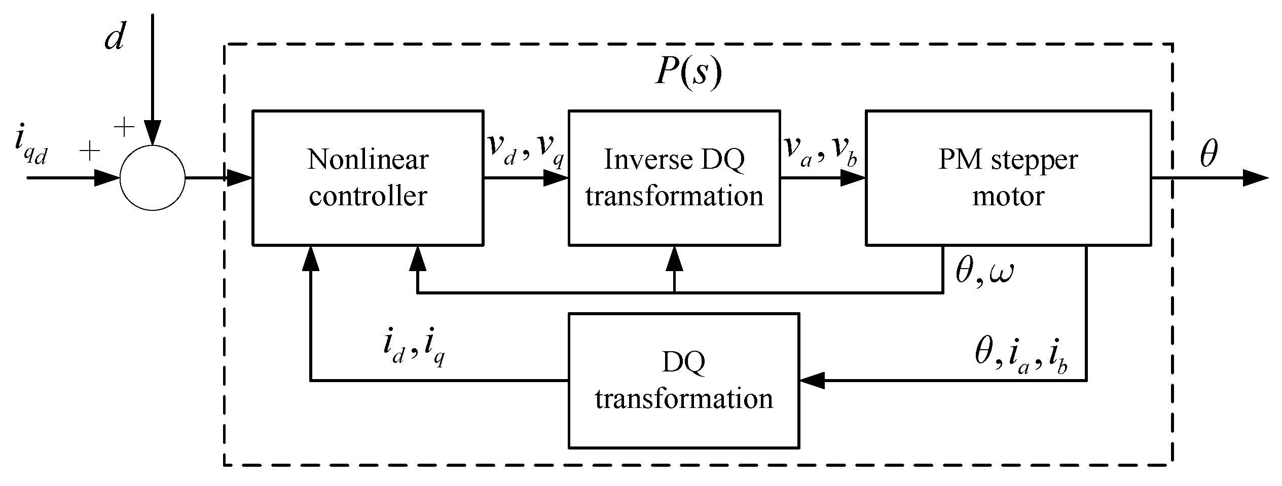
Figure 1. Permanent-magnet (PM) stepper motor with the electrical controller (4).
Applsci 11 00587 g001
Figure 2. Current error-based iterative learning controller (ILC).
Applsci 11 00587 g002
Figure 3. Structure of the proposed method.
Applsci 11 00587 g003
Figure 4. Simulation structure.
Applsci 11 00587 g004
Figure 5. Desired position and velocity.
Applsci 11 00587 g005
Figure 6. Past error-based ILC.
Applsci 11 00587 g006
Figure 7. Performance of Case 1 (proportional–integral (PI) controller).
Applsci 11 00587 g007
Figure 8. Performance of Case 2 (PI controller with past error-based ILC).
Applsci 11 00587 g008
Figure 9. Performance of Case 3 (PI controller with current error-based ILC).
Applsci 11 00587 g009
Table 1. Parameters of the PM stepper motor.
ParameterValueParameterValue
L40 mHR 14.8 Ω
J 5 × 10 5 kg·m2 K m 0.51 N·m/A
N r 50B 5 × 10 3 N·m·s/rad
Table 2. Control gains.
Control GainValueControl GainValue
k d 200 k q 200
ρ d 0.1 ρ q 0.1
k p 20 k i 0.1
Publisher’s Note: MDPI stays neutral with regard to jurisdictional claims in published maps and institutional affiliations.