Article

A Method of Two-Stage Pressure Control Based on Multistage Orifices

1
Department of Mechanical Engineering, Yanshan University, Qinhuangdao 066004, China
2
Key Laboratory of Intelligent Equipment Digital Design and Process Simulation of Hebei Province, Tangshan University, Tangshan 063000, China
3
Shanghai Electric Power Generation Equipment Co., Ltd., Turbine Plant, Shanghai 200240, China
*
Author to whom correspondence should be addressed.
Appl. Sci. 2021, 11(2), 589; https://doi.org/10.3390/app11020589
Submission received: 24 November 2020 / Revised: 16 December 2020 / Accepted: 6 January 2021 / Published: 8 January 2021
(This article belongs to the Section Mechanical Engineering)

Abstract

:

Featured Application

The pressure-control method based on multistage orifices breaks the traditional scheme of using pressure valves or directly using system pressure to realize pilot control pressure. The method has been successfully applied in electrohydraulic control systems of low-pressure steam turbine, a main equipment of power generation industry.

Abstract

The interaction of pressure and flow in a hydraulic system with multiple working conditions, multiple actuators, and large flow limits action adjustment and control. Through a pilot pressure control circuit, hydraulically operated valves can adjust pressure or direction more effectively. A recent study proposed a two-stage pressure control method based on multistage orifices and solenoid valves. The requirements of the number and diameter ratio of short orifices in the series to realize the two-stage pressure control were theoretically analyzed. Scheme design and experiment were carried out. The influence of structures of complex flow channel and solenoid valve on the higher or lower pilot control pressure was considered in the experiment. The method was experimentally verified and successfully applied in a turbine electrohydraulic control system with lower maintenance costs, making the system more reliable in the case of electrical failure. Research results provide insight into pilot pressure control in fluid systems using multistage orifices to achieve either higher or lower pressure. In addition, it has important guiding significance for the design of valves or engineering systems based on pilot hydraulic pressure.

1. Introduction

Multiactuator systems are widely used in engineering, e.g., in bionic robots, engineering machinery, and turbine electrohydraulic control systems. When a single oil source serves the hydraulic control system with multiple actuators, the actions of each actuator are restrained due to the mutual influence of pressure and flow in the circuit; therefore, independent and stable pilot control pressure is often needed in the system to meet the specific operating requirements of the actuators. Taking the electrohydraulic control system of steam turbines in power plants as an example, the opening and closing actions of multiple hydraulic motors in the steam turbine system are controlled by pilot pressure. When providing higher pilot pressure, all actuators work normally, and the change in external load force of the actuator has little influence on pilot pressure. When the turbine functions abnormally, lower pilot pressure is provided to make the main control actuator close quickly and realize an emergency shutdown. At present, there are two main methods for the formation of pilot pressure. The first method is to provide two-stage pilot pressure through an independent pump source system, which makes the overall hydraulic system structure more complex and costlier to maintain. The second method is to directly take system pressure oil as the pilot oil source. This has pilot oil pressure closely related to the working pressure of the actuator, which can cause the system with a single pump source and multiple actuators to run incorrectly. It is difficult for this method to provide low pressure for emergency stops under normal conditions.
In engineering systems, the throttling principle of an orifice is often adopted to realize single pressure control, such as using orifices to reproduce pressure conditions encountered at the inlet of steam generator tube bundles in nuclear power plants [1], installing an orifice in the pilot tube to retain pressure in the control chamber of the main valve in the pilot valve system of gas regulators [2], or controlling the fuel mixing and jet spray breakup of a liquid ejector by reducing pressure of the orifice [3]. When a single orifice is used to achieve large pressure drops, its diameter is too small and may cause problems such as liquid flash, flow blockage (in the gas flow), or serious erosion; therefore, a series of orifices with a large diameter are often adopted in engineering applications instead of a single orifice with a small diameter [4,5], such as an orifice tube with six pressure-drop stages in the process line of power plants [6] and dimethyl ether flash-boiling spray discharged through a vertical twin-orifice injector [7]. Araoye et al. pointed out that when two orifice plates were connected in series, the distance between the two had a great influence on the overall pressure drop before and after the series connection as well as the upstream flow field of the second orifice [5]. Luo et al. analyzed the damping characteristics of a two series orifices and the influence of their structural parameters on the pressure change of the control oil circuit by MATLAB [8]. Shuichi et al. investigated the thermal fluid-flow transport phenomena of twin concentric orifices with different radii installed in an axially rotating passage [9]; however, no attention was paid to the effect of the series combination of orifice plates with different diameters on the pressure at a certain point.
If more than two orifices are connected in the series, and solenoid valves are used to change the direction of oil flow, the pressure control of different levels can be realized. From the perspective of the engineering implementation of this method, components can be installed on the manifold block, and desired oil path can be obtained by drilling holes in the block to realize tubeless connection. This type of installation eliminates leakage, vibration, and noise caused by the oil pipe and pipe joint, but the layout of internal flow channel is more complicated, such as various right-angle bend structures, section shrinkage, or expansion [10,11,12,13]. Structures force the oil to change flow rate, direction, or both, resulting in additional pressure loss. When several orifices are installed in the manifold block, the flow characteristics of fluid passing through the channel structure, solenoid valve, and orifice are coupled with each other, and the flow situation is more complex. These can have an unexpected adverse effect on low-level pilot pressure control. Experiment results of many scholars showed that, when studying the flow characteristics of the orifice, obtained results by researchers using manifold block structure were always slightly higher than those obtained by researchers using horizontal pipes [14,15,16]. With the development of computer technology, many scholars used computational fluid dynamics (CFD) technology to study the fluid-flow characteristics and pressure loss of the typical channel structure in the manifold block [17,18,19,20,21,22,23,24,25]; however, these studies did not analyze the impact of manifold block structure on the pressure control circuit from the perspective of overall application. So far, there is no literature on the effect of manifold block structure on the maximal and minimal control pressure of multistage series orifices.
This paper proposes a two-stage pressure control method based on multistage orifices. Our objectives were to theoretically and experimentally verify the feasibility of the method, design a project implementation scheme on the basis of an integrated structure, and clarify the influence of structures of complex flow channels and solenoid valves on the expected two-stage control pressure value on the basis of this method.

2. Theoretical Analysis

Can high- and low-pressure control be realized at a fixed pressure point on the basis of multistage orifices? This section focuses on the theoretical feasibility of pressure control based on multistage orifices in series.
The relationship between flow rate and pressure drop through a short orifice is shown in Equation (1) [11,12,26,27,28].
Q = C d A 2 Δ p ρ = k d 2 Δ p
where Q is volume flow rate, Cd is the discharge coefficient, A is the area of orifice flow section, ρ is fluid density, Δp is pressure drop across the short orifice, d is the orifice diameter, and k is a coefficient defined as
k = π 4 C d 2 ρ .
All losses due to friction are considered in discharge coefficient Cd, which can be regarded as a constant when the flow through the orifice is in the turbulent regime [11,12,29].
W. Backè proposed the hydroelectric analogy method to analyze a hydraulic resistance network [27]. Referring to the definition of nonlinear resistance in electronics, the concept of static liquid resistance R of the orifice was introduced [4,30]. The definition is as in Equation (2).
R = Δ p Q
On the basis of Equations (1) and (2), R can be expressed as follows:
R = Δ p k d 2 = Q k 2 d 4
Equation (3) shows that the larger the diameter of the orifice is, the less the static liquid resistance.
The flow through orifices in series is equal, that is,
Q 1 = Q 2 = = Q n = Q
where terms Q1, Q2, …, Qn represent the volume flow rate of each orifice, respectively, and suffix letter n indicates the number of orifices in series.
If the effect of pipe resistance is ignored, the total pressure drop of orifices in series can be expressed as follows:
Δ p z = Δ p 1 + Δ p 2 + + Δ p n
where Δpz represents the total pressure drop of series orifice circuit and Δp1, Δp2, ⋯, Δpn represent the pressure drop of each orifice.
Combined with Equations (2)–(5), the total pressure drop of orifices in series can also be expressed as follows:
Δ p z = Q 2 k 2 1 d 1 4 + 1 d 2 4 + + 1 d n 4
where d1, d2, ⋯, dn represent the diameter of each orifice.
According to Equation (6), if two orifices are connected in series, the pressure drop of each orifice is shown as Equations (7) and (8). If three orifices are connected in series, the pressure drops of each orifice are given by Equations (9)–(11) respectively.
Δ p 2 1 = 1 1 + d 1 d 2 4 Δ p 2 z
Δ p 2 2 = 1 1 + d 2 d 1 4 Δ p 2 z
Δ p 3 1 = 1 1 + d 1 d 2 4 + d 1 d 3 4 Δ p 3 z
Δ p 3 2 = 1 1 + d 2 d 1 4 + d 2 d 3 4 Δ p 3 z
Δ p 3 3 = 1 1 + d 3 d 1 4 + d 3 d 2 4 Δ p 3 z ,
where Δp2−1 and Δp2−2 represent the pressure drop of each orifice when two orifices are connected in series, and Δp3−1, Δp3−2, Δp3−3 represent the pressure drop of each orifice when three orifices are connected in series; Δp2−z and Δp3−z represent the total pressure drop value in the two cases of series connection, respectively.
On the basis of Formulas (7)–(11), some conclusions can be drawn:
(1)
If the diameters of orifices connected in series are equal, the pressure-drop value of each orifice is also equal.
(2)
If the diameter difference between the orifices in series is large and satisfies prerequisites d1 ≥ 2d2, d2 = d3, the pressure drop of the orifice with the largest diameter is very small.
There is a difference, however, between the two cases. When two orifices are connected in series, only the smaller diameter orifice bears all pressure drops, and cavitation occurs easily in the outlet of the orifice with the smaller diameter. When three orifices are connected in series, two smaller diameter orifices can share responsibility for the whole pressure drop. Pressure loss decreases step by step, which is very beneficial to the stability of the flow characteristics of the two orifices.
On the basis of the above conclusion, if the largest diameter orifice is installed in the first place, and the diameter of other orifices in series behind is less than half of its diameter, using two or three orifices in series can obtain a high-pressure value similar to the system oil pressure from the outlet of the maximal diameter orifice. Moreover, zero pressure can be theoretically obtained at the same place when the smaller diameter orifices in series behind are “short-circuited”, for example, the oil flows back to the tank directly through the directional control valve without passing through the smaller diameter orifices in series.

3. Engineering Implementation of Two-Stage Pressure-Control Method

3.1. Implementation Principle of Engineering Scheme

The schematic diagram of the two-stage pressure control test system is shown in Figure 1. Three short orifices were connected in series, and two solenoid valves are paralleled at the second and third orifices, respectively, to realize redundant layout. Between the outlet of the first damping hole and the inlet of the second damping hole, a control oil circuit is led out to enter the pressure oil chamber of the control valve operated by the pilot hydraulic pressure, such as the control oil chamber of cartridge valve.
Three short orifices with a length of 3.5 mm (one with a diameter of 3 mm, and the other two with a diameter of 1.2 mm) were connected in series. The diameter ratio of the two differently sized orifices was greater than 2, which satisfied the theoretical analysis results. Different damping oil circuits were formed through the on–off control of four solenoid directional valves, as shown in Figure 2. Solenoid valves V1 and V3 were one group of channels, and solenoid valves V2 and V4 were another group. They could realize the redundant directional control of the damping oil circuit. Pressure sensors were installed between the two adjacent orifices, and measured pressure values were marked as Past and Pasp, respectively. Pressure Past after the first orifice outlet was the expected higher pilot control pressure, as shown in Figure 2a–c. When all electromagnets of the four solenoid valves were powered off, the second and third orifices were “short-circuited”. Oil flowing through the first orifice was directly returned to the oil tank through the solenoid directional valves (shown as Figure 2d). At this time, pressure Past formed after the first orifice outlet was the expected lowest theoretical pilot control pressure, that is, zero. The inlet pressure of the first orifice in series is represented by Ps.
The structure of the short orifice is shown in Figure 3, and its size is shown in Table 1. The short orifice had a two-stage structure. The first stage was an inner hexagonal-prism hole, and the second stage was a typical thick orifice. The flow characteristics of the short orifice were similar to those of a typical thick orifice [12]. All components shown in Figure 1 were installed in a hydraulic manifold block, as shown in Figure 4.

3.2. Reliability Analysis of Pilot Pressure Control
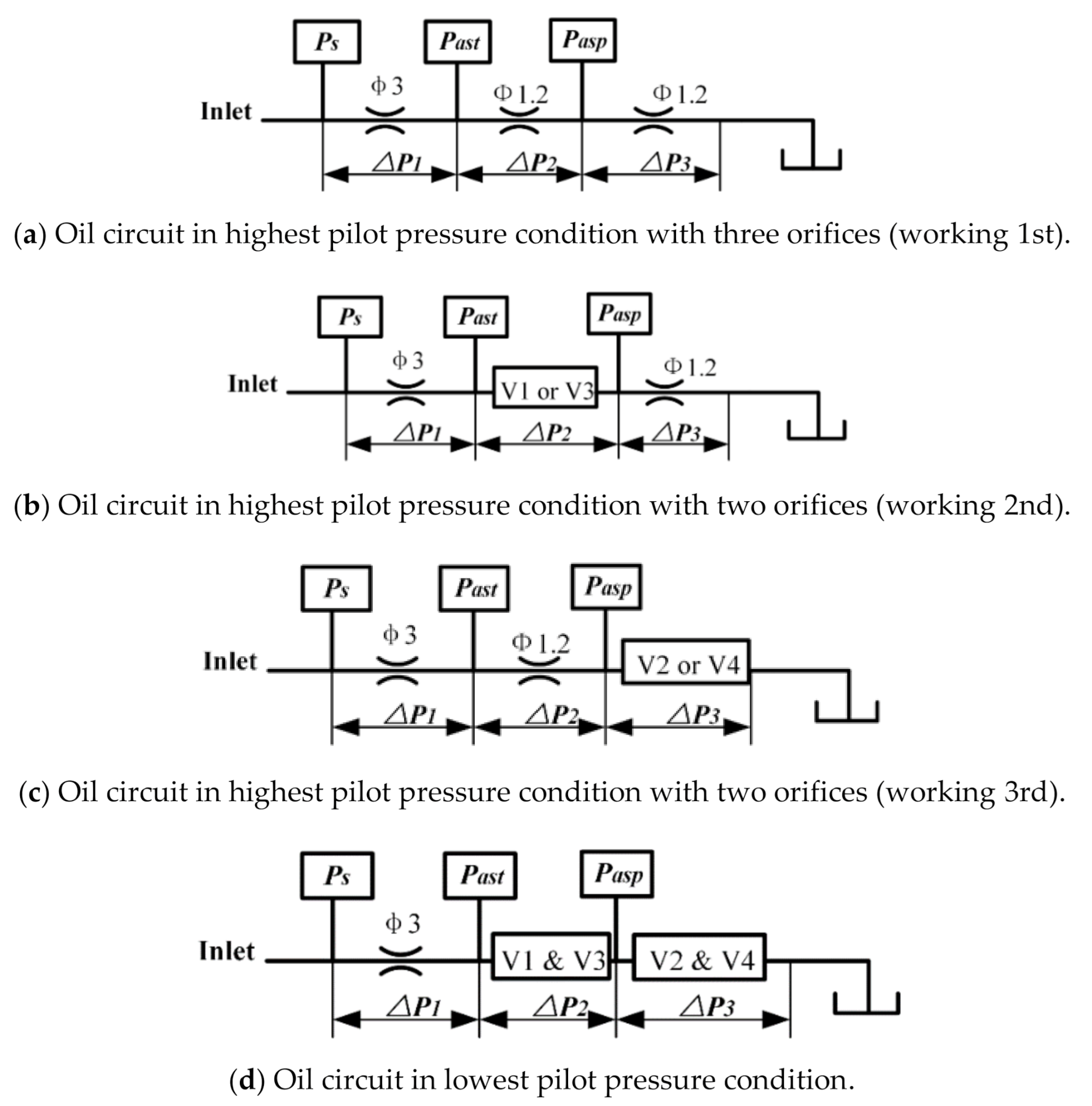
When all electromagnets of the four solenoid valves were powered on, the three orifices formed a series oil circuit (shown in Figure 2a). On the basis of Equations (9)–(11), Δp1, Δp2, and Δp3 can be expressed as:
Δ p 1 = 1 1 + 2 d 1 d 2 4 Δ p 3 z = 1 1 + 2 × 3 1.2 4 Δ p 3 z 0.013 Δ p 3 z
Δ p 2 = Δ p 3 = 1 2 + d 2 d 1 4 Δ p 3 z = 1 2 + 1.2 3 4 Δ p 3 z 0.49 Δ p 3 z
Maximal theoretical pilot control pressure Past could be obtained as shown in Equation (14), and other pressure Pasp can be expressed as Equation (15).
P ast = 0.98 Δ p 3 z = 0.98 P s
P asp = 0.49 Δ p 3 z = 0.49 P s
where Ps represents the inlet pressure of the first orifice in series.
The pressure drop of the two short orifices in series could be obtained in the same way, as shown in Equations (16) and (17); Δpφ1.2 represents the pressure drop of the second orifice with a diameter of 1.2 mm.
Δ p 1 = R 1 R 1 + R 2 Δ p 2 z = 1 1 + d 1 d 2 4 Δ p 2 z = 1 1 + 3 1.2 4 Δ p 2 z 0.025 Δ p 2 z
Δ p ϕ 1.2 = R 2 R 1 + R 2 Δ p 2 z = 1 1 + d 2 d 1 4 Δ p 2 z = 1 1 + 1.2 3 4 Δ p 2 z 0.975 Δ p 2 z
In Figure 2b, the electromagnet of solenoid valve V1 or V3 is in the power-off state, and the second orifice is “short-circuited”. Maximal theoretical pilot control pressure Past and other pressure Pasp are expressed as shown in Equation (18).
P ast = P asp = 0.975 Δ p z = 0.975 P s
In Figure 2c, the electromagnet of solenoid valve V2 or V4 is in the power-off state, and the third orifice is “short-circuited”. Pressure Past and Pasp are expressed as shown in Equation (19).
P ast = 0.975 Δ p z = 0.975 P s , P asp = 0
Compared with Equations (14), (15), (18), and (19), the different pressure values of Pasp between the two schemes of maximal pressure control with a different number of orifices in series can be found. If the electromagnet of a certain solenoid valve is not normally powered on, and the valve port is closed, pilot control pressure Past is basically unchanged, but pressure Pasp is changed obviously, as shown in Table 2. The following conclusions can be drawn:
(1)
The abnormal working state of the directional valve can be forewarned according to the pressure value of Pasp when three orifices are in series. If pressure Pasp suddenly rises, the electromagnet of the solenoid valve V1 or V3 is in the power-off state, and the second orifice is “short-circuited” (as shown in Figure 2b). If pressure Pasp suddenly drops, the electromagnet of solenoid valve V2 or V4 is in the power-off state, and the third orifice is “short-circuited” (as shown in Figure 2c).
(2)
The scheme that two orifices are connected in series to realize high control pressure has no warning function.
The final result, therefore, is to select three orifices in series to realize two-stage pressure control in order to improve the reliability of the system.

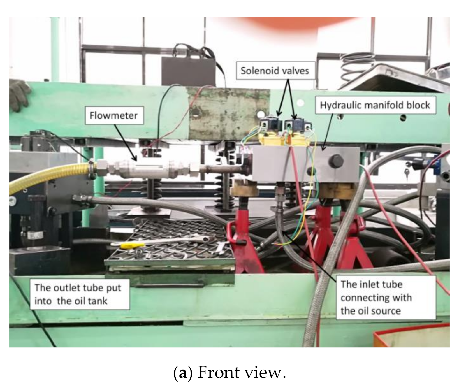
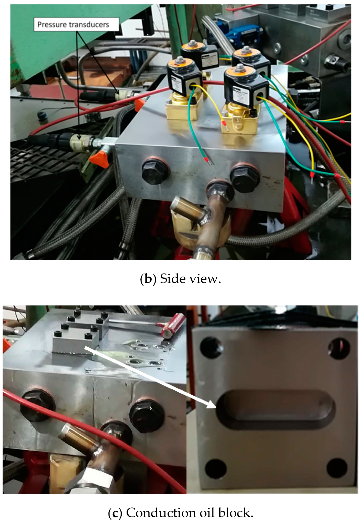
4. Test Verification and Engineering Application

4.1. Test Verification

The schematic diagram of the hydraulic test system is shown in Figure 5, and the test rig is shown in Figure 6. Two pressure sensors, three short orifices, and four solenoid valves of the same specification were integrated in the manifold block. The pressure values of Past and Pasp were measured by pressure sensors, as shown in Figure 6b. In order to further identify flow resistance, four conduction oil blocks (as shown in Figure 6c) were designed, and their function was equivalent to the fully opened solenoid valve. Each experiment was repeated three times. Sensor resolution was 0.10% F·S. In the experiment, the working medium was ISO 46 hydraulic oil, and oil temperature was between 35 and 40 °C.

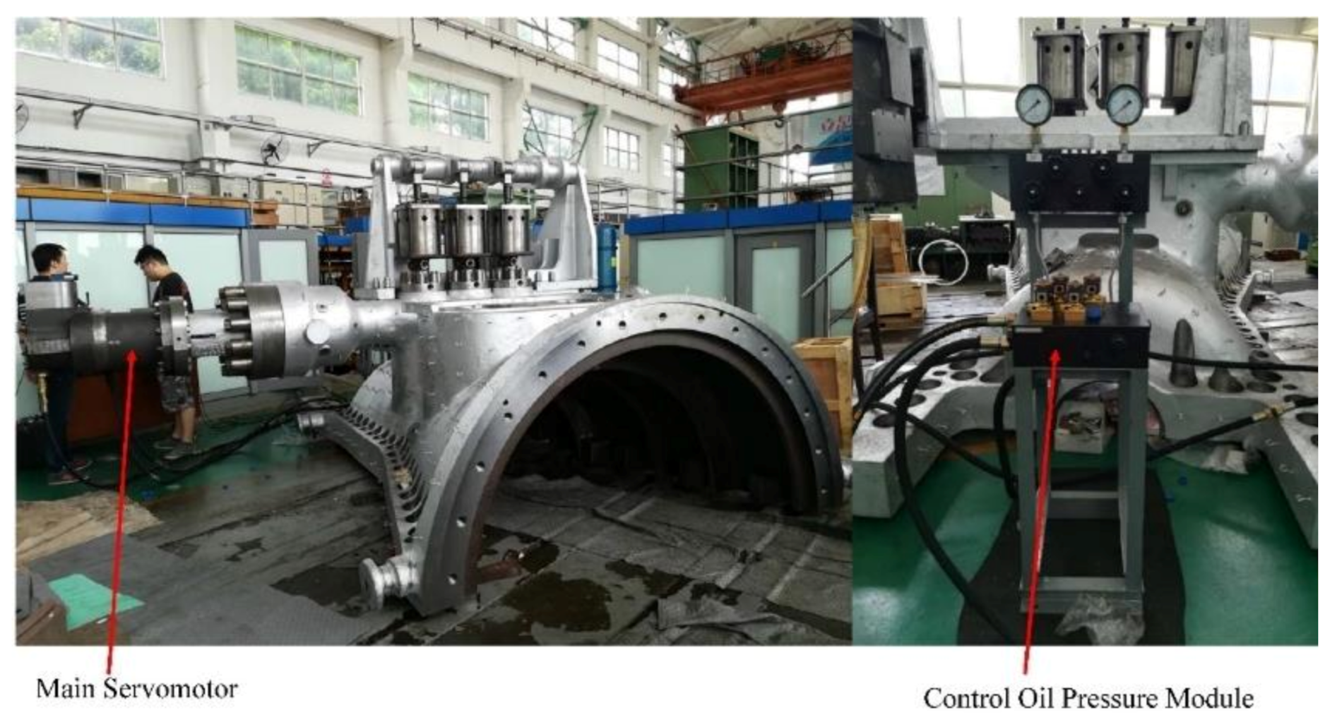
4.2. Application in Turbine Electrohydraulic Control System

Turbine electrohydraulic control systems have multiple operating conditions and multiple actuators in thermal-power generation equipment. The oil pressure-control module based on multistage orifices proposed in this paper was successfully applied to the electrohydraulic control system of a steam turbine, as shown in Figure 7. An independent and stable control oil circuit was achieved to maintain the safety of the whole system. When the system worked, it provided stable high control oil pressure, and each actuator worked normally; when the system unexpectedly failed, control oil pressure was immediately reduced to 1.4 bar, and the main servomotor was quickly closed, but system oil pressure value was basically maintained.

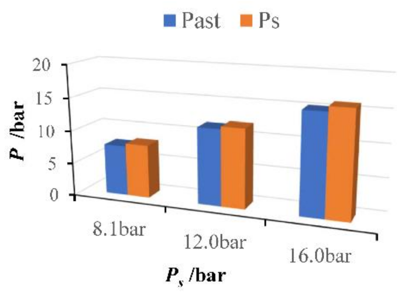
5. Results and Discussion

5.1. Pilot Control Pressure

When the four solenoid valves were powered on, the maximal pilot control pressure (Past) measured by the test was always near the oil source pressure value, shown in Figure 8. It was consistent with the theoretical analysis results that the pressure drop of the orifice with the largest diameter was very small when the diameter ratio was greater than 2.
Figure 9 shows the following phenomena. First, when three orifices were connected in series, the pressure drop of the system was mainly born by the two orifices with a diameter of 1.2 mm, which was consistent with theoretical analysis. Second, although the diameters of the second and third orifices were the same, the pressure drop was not equal. The experimental value of Δp2 was always slightly lower than the theoretical and experimental values of Δp3 were. This showed that the distance between the orifices and structure of the middle passage affected the flow characteristics of the orifices. Araoye et al. reported that orifice spacing has an obvious effect on the total pressure drop. and some important differences in the flow structure were identified upstream of the second orifice in the double-orifice configurations. Flow characteristics downstream of the multiple-orifice arrangement are qualitatively similar to those downstream of a single orifice of the same size. Accordingly, spacing between adjacent orifices has a major impact upstream and downstream of the second orifice in the three-orifice configurations. In addition, oil flow path I that produced pressure drop Δp2 was from the AST pressure measuring point, the second orifice, and then a right-angle bend to reach the ASP pressure measuring point. Path II resulting in pressure drop Δp3, which was from the ASP pressure measuring point, Π channel, the third orifice, and Z channel to the oil tank, was longer than Path I (see Figure 4b). The complex flow channel structures between the orifices also aggravated turbulence intensity [31,32].
When the four solenoid valves were powered off, the minimal achievable pilot control pressure (Past) was measured by the test, as shown in Table 3. Under this condition, the oil flow path in the manifold block was first through the first orifice with a diameter of 3 mm, and then flowed back to the oil tank through solenoid valves V1 and V3 (or conduction blocks), Π–channel, and solenoid valves V2 and V4 (or conduction blocks). Under the same system pressure of 10.6 bar, minimal pilot control pressure was 1.4 bar when using solenoid valves, and 0.3 bar when using conduction blocks. Obviously, in either case, minimal pilot pressure could not reach zero, and more pressure was produced by solenoid valves. Considering the valve’s pilot structure, certain opening pressure was required to open the valve port, resulting in minimal control pressure being affected; therefore, another experiment was actuated. Solenoid valves were replaced by conducting blocks (shown in Figure 6c), and pressure loss was reduced to 0.3 bar, which was mainly caused by the complex flow channel structure in the manifold block; therefore, it was better to use a direct acting solenoid valve to change the direction of the oil.

5.2. Reliability Verification of Pilot Pressure Control

Under system pressure of 12 bar, pilot control pressure Past and auxiliary monitoring pressure Pasp were tested under three working conditions: three orifices in series, solenoid valve V1 accidental power-off, and solenoid valve V2 accidental power-off, as shown in Table 4.
When the solenoid valve was not powered on as scheduled, the pressure value of Pasp would obviously change, but maximal pilot control pressure Past was not greatly affected. This is consistent with theoretical analysis.
Further comparison of the pressure value of Past in three different working conditions is shown in Figure 10. When three orifices were connected in series (working first), pressure Past increased with the increase in system pressure, while it decreased with the increase in system pressure under the condition of two orifices in series (working second and third). The maximal drop of pilot pressure could reach 1 bar, which may have caused the system to have a wrong action. With the increase in system pressure, pilot pressure values obtained by the two schemes with different number orifices in series showed different trends; therefore, the best scheme to realize the two-stage pressure control was to connect three orifices in series.

6. Conclusions

The paper discussed a novel two-stage pilot control pressure method based on multistage orifices and solenoid valves. It was theoretically proven that, when at least two damping holes with different diameters are connected in series as long as the diameter ratio is greater than or equal to 2, high pilot pressure close to system pressure could be obtained at the outlet of the first orifice with a larger diameter. If the second orifice is “short-circuited” by solenoid valves, low pilot pressure could be obtained at the same position. Maximal pilot control pressure was close to system pressure, and minimal control pressure was 0.3 bar, which could not be reduced to zero. The difference between the experimental and theoretical values showed that the complex flow channel structure had little effect on pilot control pressure. The experiment also showed that the control performance of pilot pressure was different with the number of orifices in series. Experiment results showed that with the increase in system pressure, pilot pressure values obtained by the two schemes with different numbers of orifices in series showed different trends. When two orifices were connected in series, pressure Past obviously decreased. When three orifices were connected in series, pressure Past increased with the increase in system pressure. In addition, the abnormal working state of solenoid valves could be warned according to pressure Past when the scheme of three orifices in series was used.
The engineering implementation of this method was successfully applied to the turbine electrohydraulic control system. Research results provide insights into the pilot pressure control in fluid systems using multistage orifices to achieve either higher or lower pressure. In addition, this could have guiding significance for the design of valves or engineering systems based on pilot hydraulic pressure. In the future, the flow field distribution characteristics of three orifices in series will be studied on the basis of a CFD simulation.

Author Contributions

Methodology, validation, and original—draft preparation, J.G.; project administration and funding acquisition, F.W.; resources and experiment, J.T.; writing—review and editing, Z.G. All authors have read and agreed to the published version of the manuscript.

Funding

This research was funded by National Major Science and Technology Projects of China, grant number 2016YFC0802900.

Institutional Review Board Statement

Not applicable.

Informed Consent Statement

Not applicable.

Data Availability Statement

Some or all data generated or used during the study are available from the corresponding author by request.

Conflicts of Interest

The authors declare no conflict of interest.

References

  1. Cioncolini, A.; Cassineri, S.; Duff, J.; Curioni, M.; Scenini, F. Micro-orifice single-phase flow at very high Reynolds number. Exp. Therm. Fluid Sci. 2018, 91, 35–40. [Google Scholar] [CrossRef]
  2. Peng, J.; Youn, C.; Takeuchi, T.; Kagawa, T. Stabilization of pilot valve system using linear flow resistance. Adv. Mech. Eng. 2017, 9, 1687814017719421. [Google Scholar] [CrossRef]
  3. Kiaoulias, D.N.; Travis, T.A.; Moore, J.D.; Risha, G.A. Evaluation of orifice inlet geometries on single liquid injectors through coldflow experiments. Exp. Therm. Fluid Sci. 2019, 103, 78–88. [Google Scholar] [CrossRef]
  4. Hu, Y.P.; Peng, Y.D.; Wu, G.M. Hydraulic Resistance Network Systems; Machinery Industry Press: Beijing, China, 2002. [Google Scholar]
  5. Araoye, A.A.; Badr, H.M.; Ahmed, W.H. Investigation of flow through multistage restricting orifices. Ann. Nucl. Energy 2017, 104, 75–90. [Google Scholar] [CrossRef]
  6. Haimin, W.; Shujuan, X.; Qingyi, S.; Caimin, Z.; Hao, L.; Eryun, C. Experiment study on pressure drop of a multistage letdown orifice tube. Nucl. Eng. Des. 2013, 265, 633–638. [Google Scholar] [CrossRef]
  7. Ju, D.; Huang, Z.; Jia, X.; Qiao, X.; Xiao, J.; Huang, Z. Macroscopic characteristics and internal flow pattern of dimethyl ether flash-boiling spray discharged through a vertical twin-orifice injector. Energy 2016, 114, 1240–1250. [Google Scholar] [CrossRef]
  8. Luo, Y.L.; Wang, Q.; Zhang, M.L. Study on damping characteristics of flow control circuit of bypass pressure compensation valve. Chin. J. Mach. Tool Hydraul. 2018, 46, 31–34. [Google Scholar]
  9. Shuichi, T.; Yang, W.J. Thermal-fluid transport phenomena in an axially rotating flow passsge with twin concentric orifices of different radii. Int. J. Energy Res. 2005, 12, 331–342. [Google Scholar]
  10. Lichtarowicz, A.; Duggins, R.K.; Markland, E. Discharge coefficients for incompressible non-cavitating flow through long orifices. J. Mech. Eng. Sci. 1965, 7, 210–219. [Google Scholar] [CrossRef]
  11. Schrank, K.; Murrenhoff, H. CFD Simulations and Experiments of the Dispersed Two-phase Flow through Hydraulic Orifices. In Proceedings of the ASME 2013 Fluids Engineering Division Summer Meeting, Incline Village, NV, USA, 7–11 July 2013; pp. 1–8. [Google Scholar]
  12. Gao, J.X.; Wu, F.H. Investigation of flow through the two-stage orifice. Eng. Appl. Comput. Fluid Mech. 2019, 13, 117–127. [Google Scholar] [CrossRef] [Green Version]
  13. Silvaa, E.A.A.; Ochoa, A.A.V.; Henríquez, J.R. Analysis and runners length optimization of the intake manifold of a 4-cylinder spark ignition engine. Energy Convers. Manag. 2019, 188, 310–320. [Google Scholar] [CrossRef]
  14. Gu, P.; Hashemian, M.; Sosale, S.; Rivin, E. An Integrated Modular Design Methodology for Life-Cycle Engineering. CIRP Ann. 1997, 46, 71–74. [Google Scholar] [CrossRef]
  15. Yamada, T.; Hasegawa, S.; Kinoshita, Y.; Yamada, S.; Inoue, M.; Rosebrock, C.; Bracke, S. Process integration concept for waste reduction among manufacturing planning, modularization and validation. Procedia Manuf. 2018, 21, 337–344. [Google Scholar] [CrossRef]
  16. Huang, R.H. Based on MINISO Compact Two-way Cartridge Valves, a New Generation of Modular, with the Group and Open Electric-Hydraulic Control Technology Combined. Hydraul. Pneum. Seals 2012, 1, 78–81. [Google Scholar]
  17. Hu, J.J.; Chen, J.; Quan, L.X.; Zhang, J.; Kong, X.D. Turbulence Model Correction and Internal Flow Characteristics Analysis of Hydraulic Manifold Blocks. Chin. J. Mech. Eng. 2017, 28, 1708–1713. [Google Scholar]
  18. Gao, X.P.; Zhang, H.; Liu, J.J.; Sun, B.W.; Tian, Y. Numerical investigation of flow in a vertical pipe inlet/outlet with a horizontal anti-vortex plate: Effect of diversion orifices height and divergence angle. Eng. Appl. Comput. Fluid Mech. 2017, 12, 182–194. [Google Scholar] [CrossRef]
  19. Grabe, C.V.; Riedel, C.; Stammen, C.; Murrenhoff, H. An Analytic Thermodynamic Model for Hydraulic Resistances Based on CFD Flow Parameters. Int. J. Fluid Power 2013, 14, 17–26. [Google Scholar] [CrossRef]
  20. Mohan, K.H.M.; Yogesh, K.K.J.; Seshadri, V. CFD Analysis of Flow through Dual Orifice Plate Assembly. Int. J. Emerg. Technol. Adv. Eng. 2015, 5, 136–144. [Google Scholar]
  21. Rito, G.D. Experiments and CFD Simulations for the Characterisation of the Orifice Flow in a Four-Way Servovalve. Int. J. Fluid Power 2007, 8, 37–46. [Google Scholar] [CrossRef]
  22. Shah, M.S.; Joshi, J.B.; Kalsi, A.S.; Prasad, C.S.R.; Shukla, D.S. Analysis of flow through an orifice meter: CFD simulation. Chem. Eng. Sci. 2012, 71, 300–309. [Google Scholar] [CrossRef]
  23. Singh, V.K.; Tharakan, T.J. Numerical Simulations for Multi-hole Orifice Flow Meter. Flow Meas. Instrum. 2015, 45, 375–383. [Google Scholar] [CrossRef]
  24. Cao, Y.N.; Tian, S.J.; Wang, Y.A.; Zhang, H. HMB Duct Nets’ Dynamic Characteristic Simulation Based on Typical Flow-resistance. J. Syst. Simul. 2009, 21, 3460–3463. [Google Scholar]
  25. Xie, G.Q.; Li, Y.C. Simulation and Analysis for Flow Field of Typical Channel Inside Hydraulic Manifold Block Based on Fluent. Chin. J. Hydr. Pneum. 2013, 12, 44–47. [Google Scholar]
  26. Backe, W. Hydraulic Resistance Loop Systems; Machinery Industry Press: Beijing, China, 1980. [Google Scholar]
  27. Tamburrano, P.; Plummer, A.R.; Distaso, E.; Amirante, R. A review of electro-hydraulic servovalve research and development. Int. J. Fluid Power 2019, 20, 53–98. [Google Scholar] [CrossRef]
  28. Merritt, H. Hydraulic Control System; John Wiley and Sons: New York, NY, USA; London, UK; Sydney, Australia, 1967. [Google Scholar]
  29. Johansen, F.C. Flow through Pipe Orifices at Low Reynolds Numbers. Proc. R. Soc. A 1930, 126, 231–245. [Google Scholar]
  30. Sheng, J.C. Hydraulic Fluid Dynamics; Machinery Industry Press: Beijing, China, 1982. [Google Scholar]
  31. Shan, F.; Fujishiro, A.; Tsuneyoshi, T.; Tsuji, Y. Particle image velocimetry measurements of flow field behind a circular square-edged orifice in a round pipe. Int. J. Heat Mass Transf. 2013, 73, 542–550. [Google Scholar] [CrossRef]
  32. Modi, P.P.; Jayanti, S. Pressure losses and flow maldistribution in ducts with share bends. Chem. Eng. Res. Des. 2004, 82, 321–331. [Google Scholar] [CrossRef]
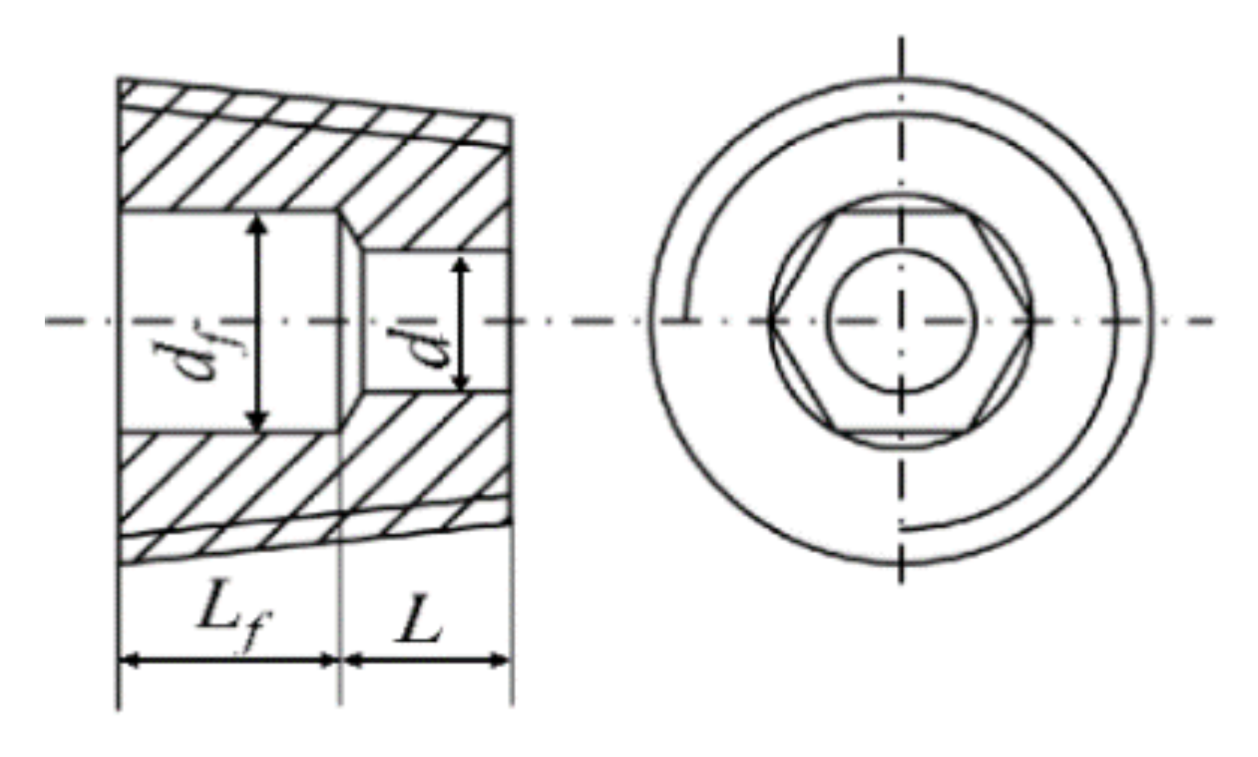
Figure 1. Schematic diagram of two-stage pressure control.
Applsci 11 00589 g001
Figure 2. Two different levels of pilot control pressure circuit: (a) Oil circuit in highest pilot pressure condition with three orifices (working 1st); (b) Oil circuit in highest pilot pressure condition with two orifices (working 2nd); (c) Oil circuit in highest pilot pressure condition with two orifices (working 3rd); (d) Oil circuit in lowest pilot pressure condition.
Applsci 11 00589 g002
Figure 3. Structure of short orifice.
Applsci 11 00589 g003
Figure 4. Structure of manifold block: (a) Three-dimensional model of manifold block; (b) Types and main sizes of complex flow channels.
Applsci 11 00589 g004
Figure 5. Schematics of hydraulic testing system.
Applsci 11 00589 g005
Figure 6. Test rig: (a) Front view; (b) Side view; (c) Conduction oil block.
Applsci 11 00589 g006aApplsci 11 00589 g006b
Figure 7. Physical diagram of system application.
Applsci 11 00589 g007
Figure 8. Maximal pilot control pressure at different system pressure levels (experimental data).
Applsci 11 00589 g008
Figure 9. Comparison of pressure drop under different system pressure levels.
Applsci 11 00589 g009
Figure 10. Comparison of pressure drop from Conditions 1 to 3 (experiment data).
Applsci 11 00589 g010
Table 1. Orifice dimensions (mm).
d 1df 2LLf
34.73.54.5
1.24.73.54.5
1 diameter of short orifice, 2 diameter of inscribed circle of hexagon.
Table 2. Judgment rules of solenoid valve state.
ConclusionNormalV1 or V3
Abnormal
V2 or V4
Abnormal
Pressure
Past0.98Ps0.975Ps0.975Ps
Pasp0.49Ps0.975Ps0
Table 3. Minimal pilot control pressure Past.
ConclusionSolenoid ValveOil BlockTheoretical Value
Pressure
Past (bar)1.40.30
Pasp (bar)0.70.30
Table 4. Pressure data sheet for abnormal state test of solenoid valve.
ConclusionNormalV1 or V3
Abnormal
V2 or V4
Abnormal
Pressure
Past (bar)11.611.211.2
Pasp (bar)5.310.50.6
Publisher’s Note: MDPI stays neutral with regard to jurisdictional claims in published maps and institutional affiliations.

