Article

Acoustic and Flow Aspects of Synthetic Jet Actuators with Chevron Orifices

1
Faculty of Mechanical Engineering, UTP University of Science and Technology, Al. Prof. S. Kaliskiego 7, 85-796 Bydgoszcz, Poland
2
Faculty of Mechanical Engineering and Aeronautics, Rzeszow University of Technology, al. Powstańców Warszawy 12, 35-959 Rzeszów, Poland
*
Authors to whom correspondence should be addressed.
Appl. Sci. 2021, 11(2), 652; https://doi.org/10.3390/app11020652
Submission received: 18 December 2020 / Revised: 5 January 2021 / Accepted: 7 January 2021 / Published: 11 January 2021
(This article belongs to the Section Mechanical Engineering)

Abstract

:
The use of a chevron nozzle/orifice is one of the methods of heat transfer enhancement and noise reduction. In the case of synthetic jets, the number of papers on this topic is small. Therefore, a synthetic jet actuator with three different chevron orifices and one circular orifice is investigated. The aim of this study is to find the impact of orifice shape on centerline velocity (measured with a hot-wire anemometer) and determine if the chevron orifice reduces the generated noise. The sound pressure level was strongly dependent on the input actuator’s power, and only one chevron orifice ensured noise reduction for low power (p = 6; 8 W). At real power p = 12 W, the sound pressure level was lower for each chevron orifice actuator than in the case of the circular orifice actuator. It is shown that the application of a chevron nozzle does not have to provide noise reduction. It is important in the case of the design of new actuators that are to operate in places where noise levels should be limited (e.g., offices).

1. Introduction

The synthetic jet (SJ) is generated by periodic expulsion and injection of fluid to a closed cavity through an orifice. This is achieved by replacing one of the walls of the synthetic jet actuator (SJA) with movable or deformable elements such as piezoelectric, acoustic (loudspeaker), or mechanical (piston) drivers. The SJAs can be used in electronic cooling [1,2,3], flow control [4,5,6], or mixing [7,8,9].
The use of SJs on a larger scale in the industry requires compliance with many standards. Among them are the ones regarding the level of generated noise. Jabbal and Jeyalingam [10] investigated the noise level generated by single-chamber and double-chamber actuators with lobed and circle orifices. Double-chamber actuators generated a lower noise level than single chambers at all tested frequency ranges. A lobed orifice was quieter than a circular orifice at frequencies below 2.1 kHz. The impact of orifice shape on the noise level generated by SJAs has also been investigated [11,12,13]. Arik had the idea of closing the SJA in a small box with a muffler [14]. Such a solution reduces the generated noise but is impractical.
Another popular way for decreasing the sound pressure level (SPL) is the use of a chevron nozzle [15,16]. Chevron nozzles are used in medium- and high-bypass turbofan engines, and they represent one of the most popular noise reduction technologies [17,18]. The shape of the chevron nozzle increases mixing between the adjacent streams and reduces the velocity gradient. This reduces the generated noise. Chevron nozzles are also used in other active and passive applications, for example, in continuous impinging jets [19].
At this point, the difference between a nozzle and an orifice must be pointed out. A nozzle is a device that is used to increase stream velocity. Therefore, in the case of subsonic flows (like in the case of SJs), the cross-section area of the nozzle must decrease in the direction of flow. The orifice’s cross-section area is invariable all along of length. In the case of SJs, the term “nozzle” is sometimes misused in relation to the orifices. Such abuse of the word “nozzle” can be observed, for example, in [20,21,22].
Crispo et al. [15] compared the velocity field of SJAs with a circular nozzle and a chevron nozzle with six chevron nozzles. The parameters were investigated in the apex and notch planes of the chevron nozzle. The velocity time-averaged component and time- and phase-averaged turbulent kinetic energy were measured with the stereoscopic particle image velocimetry (Stereo-PIV) method. The velocity profiles in the apex and notch planes were different from each other. The axial velocity component was smaller in the apex plane than the circular SJ; in the notch plane, it was higher. However, the most important thing was to show the difference in the shape of the vortex topology. The actuator with a chevron nozzle generates a more complex flow field, with streamwise vortices that change the shape of the vortex ring. The streamwise vortices disappear very quickly, and the vortex topology is similar to the circular shape for x/d > 3 (where x is the axis distance from the nozzle [m], and d is the nozzle diameter [m]).
Lyu at al. [21] investigated piston-driven SJAs with chevron orifices. They showed that the use of a chevron nozzle and a chevron orifice provides similar results in terms of Nusselt number distribution. It can, therefore, be assumed that the chevron nozzle and the chevron orifice can be used equally in continuous impinging jets. The chevron orifice was compared to the chevron nozzle presented in [23]. The same nozzle was used by Crispo et al. [15]. Lyu at al. [21] focused on the impact of the orifice-to-surface distance on the radial distribution of circumferentially-averaged Nusselt numbers. The impact of the orifice length was investigated as well. The benefits of SJ heat transfer enhancement were confirmed for the chevron orifice, and the negative impact of orifice length on the Nusselt number was described.
A similar conclusion was presented by Crispo et al. [16,24]. However, in [24], impinging SJ at a short nozzle-to-surface distance (H/d = 2, where H is the nozzle-to-surface distance) was investigated, and the three-dimensional reconstruction of the flow field with PIV was presented. The evolution of the vortex ring impinging onto the wall was demonstrated.
The number of papers that have investigated SJAs with chevron nozzles/orifices is small, and none of them have investigated the effects of changing the nozzle/orifice shape on the generated noise. The orifice shape has a significant impact on the SPL [11,12,13], and although it is widely believed that the chevron nozzle reduces noise, research has shown that this may not always be true [25].
The purpose of this article is to investigate the effect of orifice shape on velocity and the generated SPL, parameters that are relevant for industrial applications. Three different chevron orifices and one circular orifice are investigated; the chevron orifices were designed from scratch. The second purpose of the paper is to check if the common assumption that the use of a chevron orifice provides SPL reduction is correct.
It is very important that in this paper, an orifice was used and not a nozzle. In [21], a chevron nozzle and a chevron orifice were compared using their Nusselt numbers but not their noise levels. An orifice is much cheaper and easier to produce than a nozzle, and it is very important in commercial applications. Therefore, it should be confirmed if the use of a chevron orifice reduces noise levels and whether a chevron orifice can have any shape or not.

2. Materials and Methods

An SJA with four different orifices is investigated in this paper. The actuator consists of a loudspeaker STX W.18.200.8.FGX fitted with an actuator’s body made of PMMA. The diameter of the actuator cavity is 150 mm, and the cavity height is 20 mm. Three different chevron orifices and one circle orifice were used. The orifices were printed using 3D technology from PETG, and the finished prints were treated to remove 3D-printing errors. The specifications of the nozzles and the SJA is presented in Table 1, and the most important parameters of the orifices are presented in Figure 1. The length of the printed orifices amounted to 40 mm. In Table 1, the total orifice length has been entered, and it is the sum of the length of the printed orifice and the thickness of the actuator body plate.
The actuator was supplied with sinusoidal signals generated by a Rigol DG4162 waveform generator and strung by an AUNA CD-708 amplifier. The electrical power feeding the SJA was calculated by measuring the effective voltage and effective current supplied to the actuator. The current was measured indirectly using a current shunt with a reference resistor (1 Ω, 0.01%). Voltage drops were measured with a Keithley 2701 mm instrument (6.5 digits, 22-bit) with a 7706 all-in-one I/O module.
The energetic efficiency of the actuators was calculated using the reaction force measurement method [26,27]. For this reason, the SJA was placed in a precision balance RADWAG WTC2000, with a resolution of 0.01 g and a range of 2000 g. Additionally, axis velocity was measured with a two-wire constant temperature anemometer (CTA) probe connected to the ATU 08 bridge. The probe has been calibrated to the velocity range of 0.3–49 m/s. The second wire of the probe was used to measure the temperatures and temperature compensation of the velocity measurements that were used. The CTA probe was mounted on a 3D manipulator with ±0.02 mm positioning accuracy.
A Testo 816-1 sound-level meter was used for the SPL measurements. It complied with the requirements of the IEC 61672-1 Class 2 standard and was equipped with a ½ “microphone; its measuring range was 35–130 dB (A) in a frequency range of 20–8000 Hz. The sound meter was located 1 m from the test stand. The background SPL of the environment was confirmed to be at least 10 dB lower than the SPL generated by the SJA. Type A frequency weighting was applied to the SPL measurements—SPL (A).
Atmospheric pressure was measured using a Honeywell HPB200W2DA-B barometer, with an accuracy of ±40 Pa.
All devices were controlled using LabVIEW software with the National Instruments NI-USB-6211 card. The scheme and a photo of the measurement stand are presented in Figure 2 The accuracy of the measured value is presented in Table 2.

2.1. Data Reduction

Velocity is one of the basic parameters used to calculate almost all parameters investigated in SJs [28]. Kordick et al. [29] showed that centerline velocity is the representative value in the case of axisymmetric SJs. For this reason, only the centerline velocity of SJs is measured in this paper. The following velocities were used [30]:
  • Local centerline momentum velocity:
    U rms . c = 1 T ( u c 2 ) d τ ,
  • Local centerline time-averaged velocity:
    U avg . c = 1 T u c d τ ,
  • Local centerline maximum velocity:
    U max . c = max ( u c ) ,
    where T is the operation period of the loudspeaker membrane [s], and uc is the instantaneous velocity at the orifice axis [m/s].
Additionally, the centerline synthetic jet turbulence intensity is defined as
T u = 1 T ( u c U avg . c ) 2 d τ U avg . c ,
The energetic efficiency of SJs is calculated by reaction force measurements. This method is described in [27]. The efficiency is calculated as
η = 1 2 P F 3 A 0 · ρ ,
where F is the time-average reaction force measured by the precision balance [N], A 0 is the cross-section of the orifice [m2], ρ is the air density calculated from the ideal gas formula [kg/m3], and the real power is calculated as
P = E I · c o s ( φ ) ,
where E . is effective voltage [V], I is effective current [A] and c o s ( φ ) is the power factor. An impendence measurement is used to designate it:
Z = E I ,

2.2. The Experiment Plan

During the experiment, the SJA and each orifice were tested in the same way:
  • Velocity (x/d = 0, the axial distance x and diameter d are showed in Figure 1a) and impedance measurements for different frequencies. The tested frequency range was from 8 to 100 Hz, with steps of 1 Hz. The measurements were carried out at real power p = 3 W.
  • The energetic efficiency measurements for different real powers at the characteristic frequency. The measurements were carried out at real power p = 0.02, 0.05, 0.1, 0.5, 1, 1.2, 5, 2.5, 3, and 3.5 W.
  • The measurements of velocity in the time function at the characteristic frequency, real power p = 3 W, and x/d = 0, 3.
  • The velocity measurement in the function of ratio x/d at the characteristic frequency and real power p = 3 W.
  • The SPL measurement at the characteristic frequency and real power p = 5, 6, 8, 10, and 12 W.

3. Results and Discussion

3.1. A Search of Characteristic Frequency

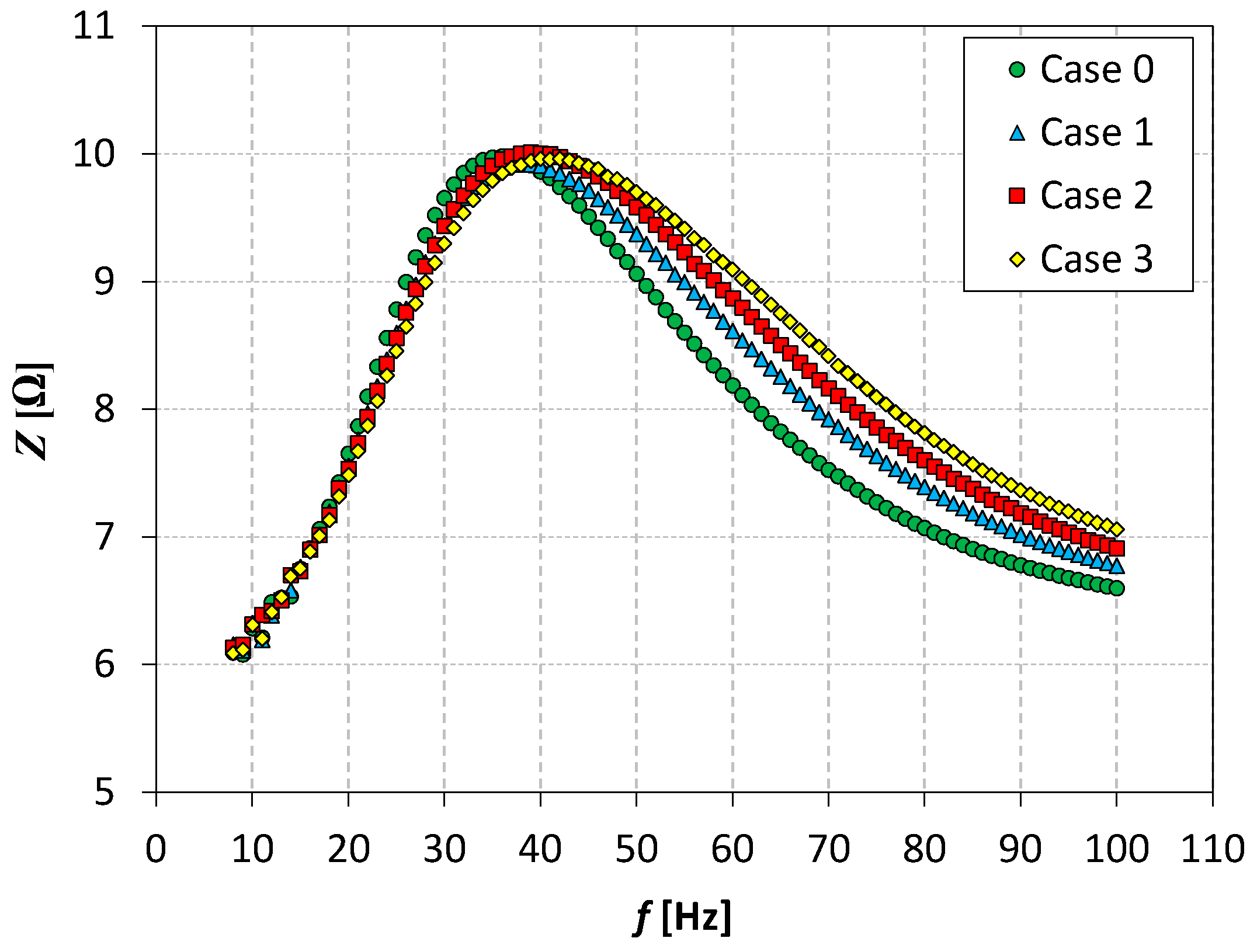
The electrical impedance of the SJA as a function of actuator frequency is shown in Figure 3. The impedance had only one extremum in the investigated range, and the maximal value for all the cases was similar and within the range of Z = 9.9–10.1 Ω. Based on the extremum, the characteristic frequency for each case was designated and is presented in Table 1. The characteristic frequencies were similar to the characteristic frequencies of the used loudspeakers, which was 37 Hz. For this reason, the designated frequency has been identified as a natural frequency. The theme of the characteristic frequency of the actuator is widely described in [31].
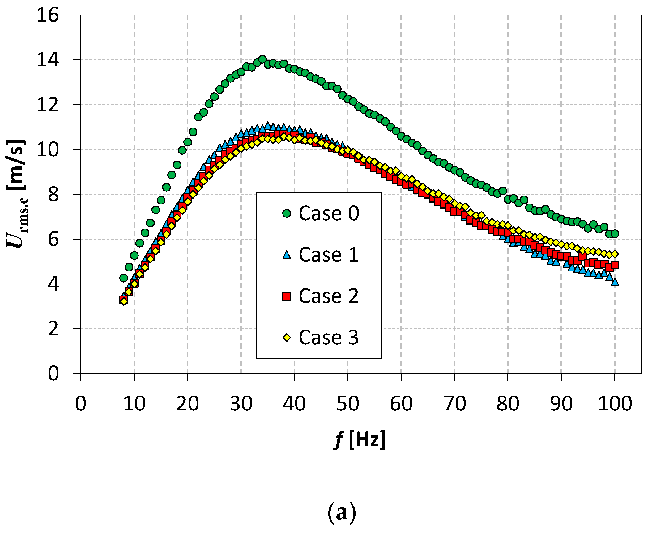
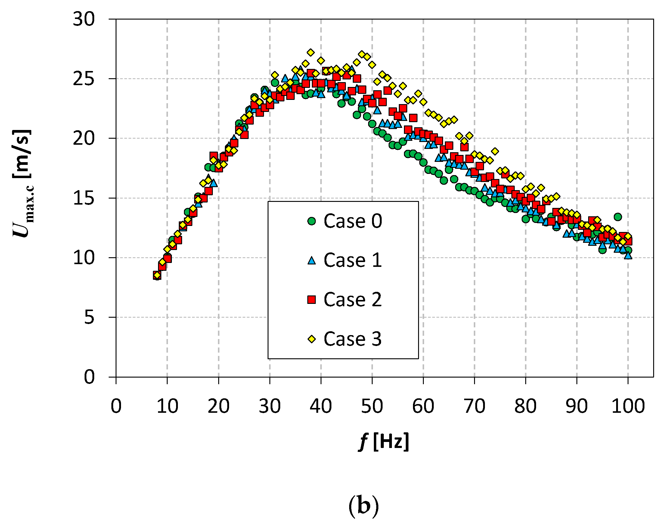
The averaged and maximum velocity of SJs in the centerline at the distance of x/d = 0 is shown in Figure 4. The highest time-averaged velocity was obtained in Case 0 for the circular orifice and was even about 12–15% higher than in the other cases with chevron orifices at the natural frequency. The significant decrease in average velocity was surprising, especially because the difference in the case of chevron orifices was not big and was obtained at about 1% at the natural frequency. Generally, the larger the chevron cutouts in the orifice, the smaller the time-average velocities for frequencies lower than 50 Hz. The maximum velocity of SJs has a reverse trend to averaged velocity; the larger the chevron cutouts in the orifice, the higher the maximum velocity. It is an important dependence that shows significant differences in the flow-through and around the orifice. It is widely discussed in Section 3.2.

3.2. The Efficiency Measurement

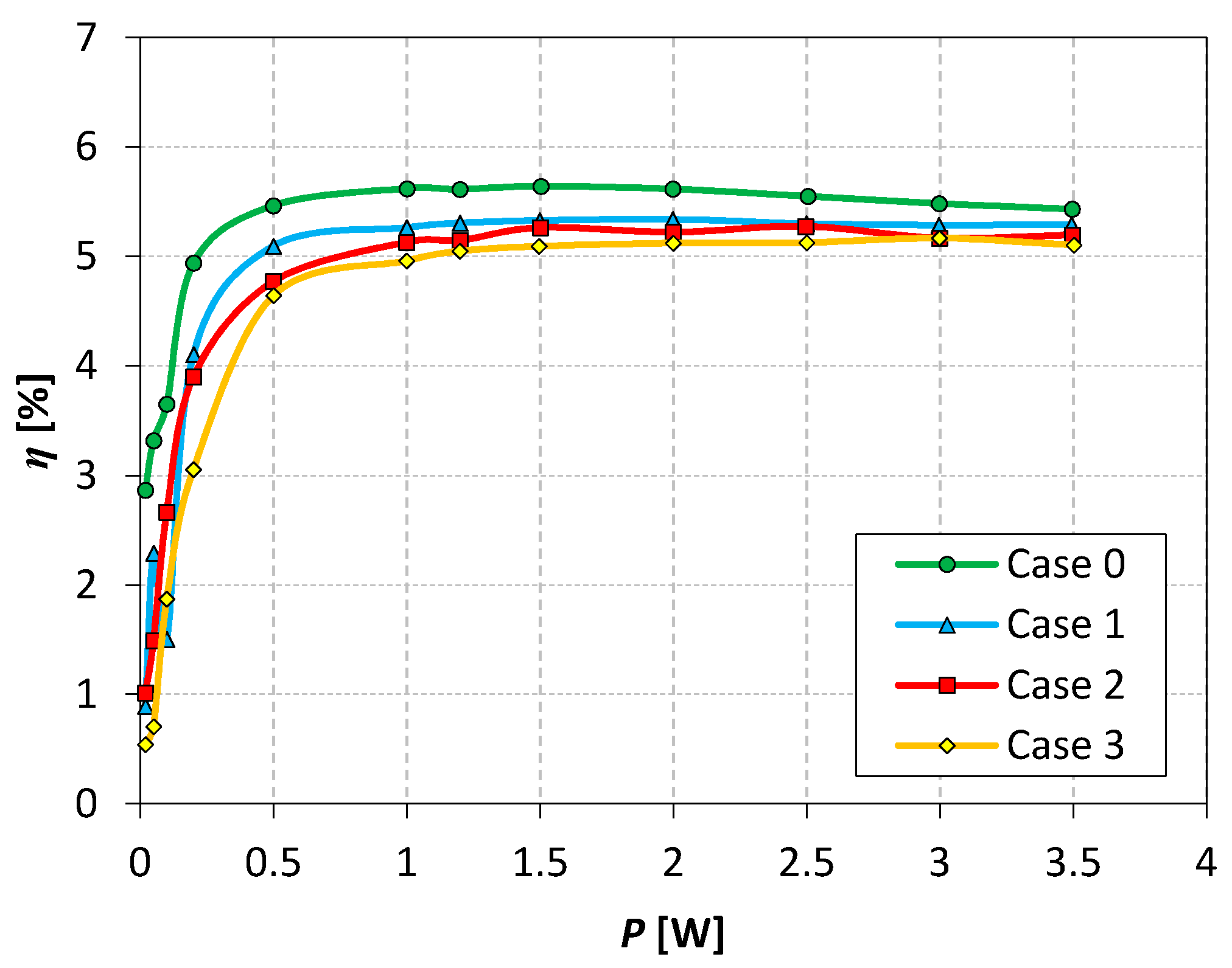
The electrical efficiency of SJAs as a function of real power is shown in Figure 5. The highest efficiency was carried out in Case 0, then in Case 1 and Case 2; lower efficiency was obtained in Case 3. The efficiency increased the logarithmic value, and after reaching the maximum value, it did not show a significant change. The maximum value of efficiency was 5.6%, similar to the work in [32], wherein the same loudspeaker and cavity size were used. The difference between the efficiency in Case 0 and Case 3 is about 5.9% of the measured value, at real power p = 3 W.

3.3. Centerline Velocity in Time Function

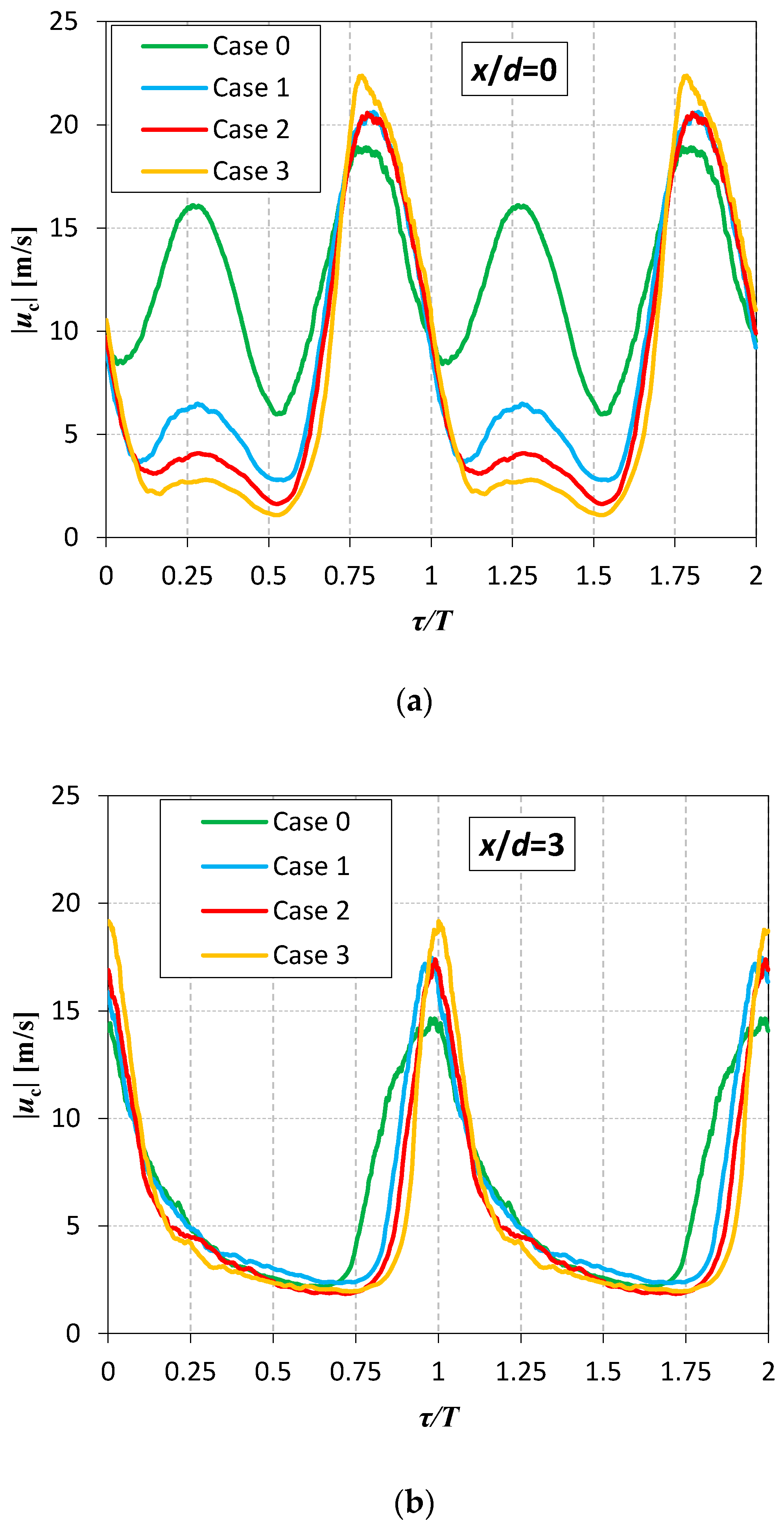
Velocity as a function of time is shown in Figure 6. The absolute velocity is presented because the used CTA probe does not recognize the flow direction and measures only the velocity’s magnitude. The centerline velocity at ratio x/d = 0 is presented in Figure 6a. There are two stages in the course of the function. The stage of injection is when the air is sucked into the cavity (0 ≤ τ/T ≤ 0.5), and the stage of expulsion is when the air is blown out of the actuator cavity (0.5 ≤ τ/T ≤ 1).
In the stage of injection, the highest velocity was obtained in Case 0; the higher the chevron cutouts in the orifice, the lower the velocity. The air is injected through the surroundings of the orifice, and, in the case of a circular nozzle, the volume of air flows through the circular area of the orifice exit. In the center point of this area, the velocity is measured with the CTA probe. In the case of the chevron orifice, the air is also injected through chevron cutouts in the orifice wall, and the airflow area is much bigger than in the case of the circular orifice. Additionally, the air is drawn in from a larger area around the orifice than in the case of the circular orifice. The injected volume of flow and the injection time are the same, but the flow area increases for each following case. For these reasons, the measured velocity is smaller in each following case.
The blow velocity of SJs was highest in Case 3 and lowest in Case 0. The difference was around 15%. It confirms the results presented in Figure 4b. The bigger the chevron cutouts, the higher the velocity. This may be due to the reduction of viscous forces and more harmonious separation of the stream from the orifice wall. However, the exact cause of this is unclear and should be additionally investigated by the PIV or a numerical method.
Centerline velocity at ratio x/d = 3 is presented in Figure 6b. For this distance from the orifice, the injection stage is not visible at the measured velocity—Gil et al. [30] showed that the change of velocity vector direction in the centerline no longer occurs at x/d = 2. The expulsion stage is still visible as a peak of velocity. The highest velocity was obtained in Case 3 and the lowest in Case 0. The results coincide with the results discussed previously.

3.4. The Axial Distribution of Centerline SJ Velocity

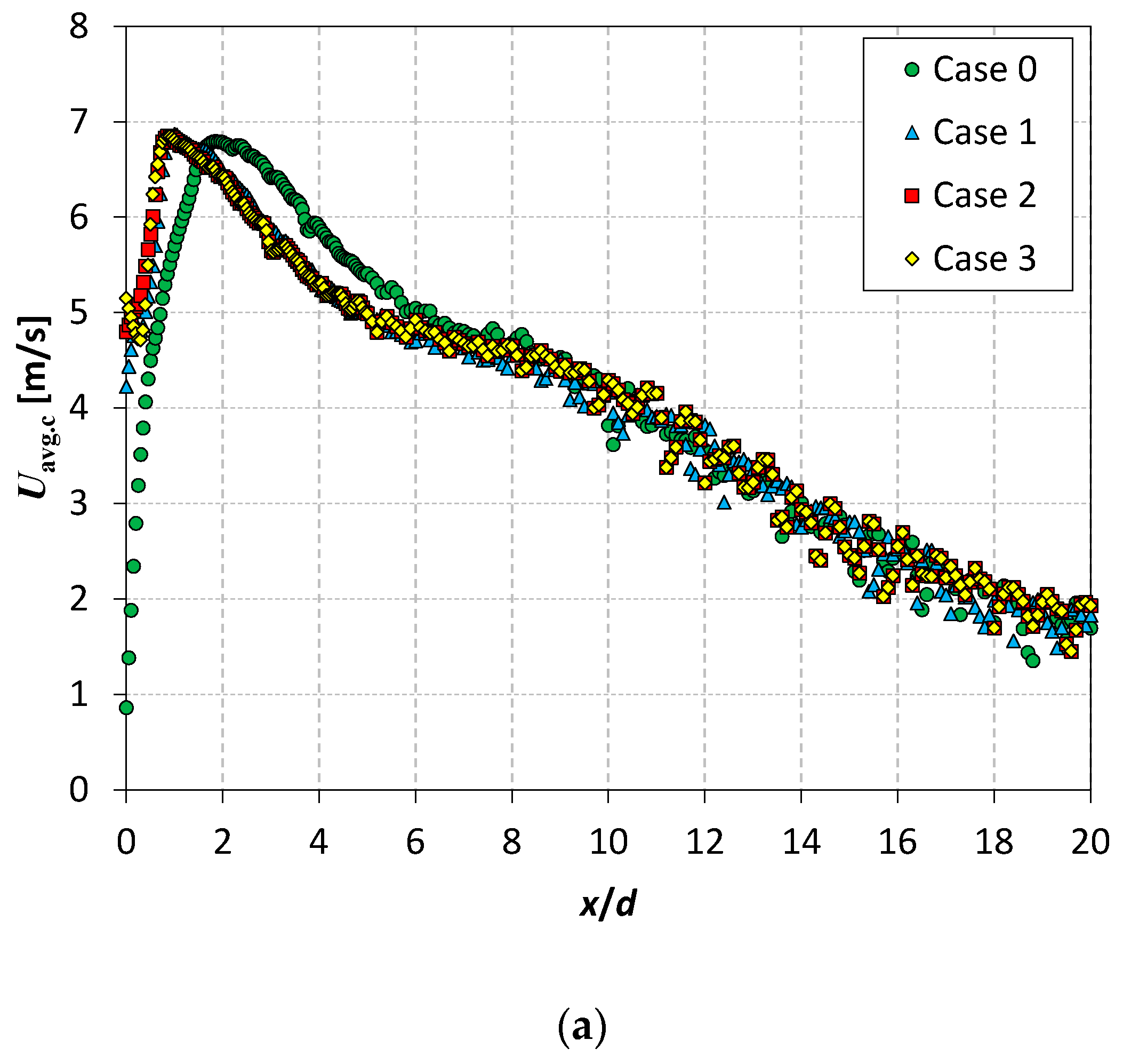
The axial distribution of centerline SJ velocity and turbulence intensity is presented inFigure 7. In Figure 7a, the centerline time-averaged velocity is presented. In Case 0, the velocity value tends to zero at x/d = 0. It is caused by almost-equal velocity in the injection and expulsion stages (Figure 4a). In the case of an actuator with a chevron orifice, the centerline time-averaged velocity is bigger than 4 m/s at x/d = 0. Then, the velocity increases, and, reaching the maximum value at 0.4 < x/d < 1.3, the velocity decreases. Case 3 is an exception. The centerline time-averaged velocity reaches the maximum value at x/d = 0, and then it decreases.
The centerline time-averaged velocity still decreases with ratio x/d [30,33,34]; such a tendency is observed in Figure 7a. A similar course to centerline time-averaged velocity has been observed in [30], but the authors did not comment on that. Krishnan and Mohseni [35] postulated that it was associated with a change of SJ form and called this region a transition region. They tested an SJ with a rectangular orifice, and, for that reason, the investigation of this phenomenon cannot be transferred to the present results. However, it can be associated with a change of vortex ring shape [15].
The centerline momentum velocity is similar for each case (Figure 7b). The highest value of momentum velocity was obtained at x/d = 0 and then it decreased. Although the initial values differ significantly (centerline momentum velocity in Case 0 is about 22% higher than in Case 2 at x/d = 0), the velocity values are already equalized at x/d > 0.5.
The maximum velocity of the SJ is presented in Figure 7c. The velocity is highest at x/d = 0, and then it decreases in Case 0 and Case 1. The maximal value of SJ increases in Case 2 and Case 3. However, in Case 3, it increases for about 0.2 m/s (less than 2% of the value) and it is a value below measurement uncertainty (Table 2); therefore, this cannot be considered significant. In Case 3, the maximal velocity increases at about 7% in the range of 0 < x/d < 0.9, then it decreases. The maximal velocity value is similar for all cases at x/d > 7.
The centerline turbulence intensity of SJ is presented in Figure 7d. The turbulence intensity for circular orifice SJAs is the highest at x/d = 0, and then it decreases; it could have a local maximum [30]. The local maximum of all the measured cases is obtained at 4 < x/d < 5. For a similar ratio x/d, the local maximum appears in [30] (x/d = 4.4). Centerline turbulence intensity trends to 0.4 and reaches a value close to zero at x/d > 12; in [30], intensive turbulence reached a value close to zero at x/d > 15.
This is quite a distance from the nozzle (93–116 cm). Chaudhari et al. [36] showed that the heat transfer coefficient was highest at the distance of 50 mm and was not dependent on the orifice diameter in the case of the use of SJAs as an impinging jet. For the investigated orifices, it is x/d = 2.5. At that distance, centerline maximum velocity is higher for about 11–30% of cases with chevron orifices than in Case 0, and centerline turbulence intensity is higher for about 34% of cases with chevron orifices than in Case 0. For these parameters of SJ velocity, the thermal boundary layer should be better disturbed, and probably, for this reason, the chevron nozzle is more useful in cooling applications [37].

3.5. Noise Level

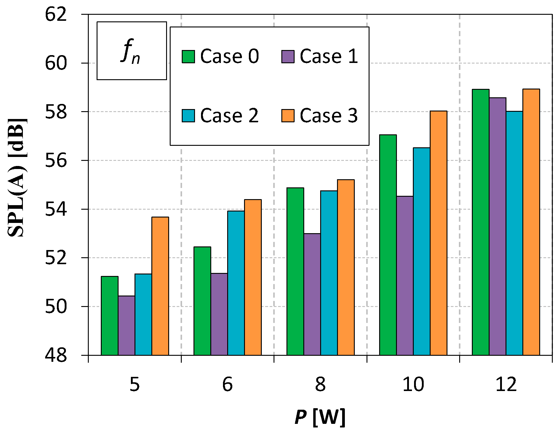
In Figure 8, the noise level as a function of real power for all cases is presented. The SPL(A) for all cases can be interpolated as the exponential function ( S P L ( A )   =   a · e b · P ) with different a and b parameters and the coefficient of determination R2 > 0.9. The highest value of SPL(A) is obtained in Case 3. The noise generated in Case 1 is always lower than in Case 0. The SPL(A) in Case 2 is bigger than in Case 0 at p = 5, 6 W, and for greater real power, it is lower. To sum up, in only Case 1, the noise is reduced by about 1–2% when compared to Case 0.
It must be noted that, generally, the higher the chevron cutouts, the highest the SPL (except in Case 1 at p = 12 W). Along with increasing chevron cutouts, the height of the angle between the walls formed after “removing” the chevron decreases. On this basis, we assume that at this point (the vertex of chevron cutouts), the sound may be, in some way, amplified. This hypothesis is supported by the fact that for small power levels, the SPL generated in Case 3 is much bigger than in Case 0. Along with the increase in power, this effect is less and less important, and, finally, at p = 12 W, it is reduced by the benefits of the overall shape of the chevron orifice. However, this hypothesis should be tested and confirmed/rejected by thorough research of the sound field around the orifice.
Most often, during investigations of SJAs with chevron nozzles or orifices, it is assumed that the chevron nozzle generates less noise than the classic circular nozzle. However, this issue has not been verified (e.g., in [15,19]). There has been a simple transfer of assumptions from aviation to SJA techniques. The present paper shows that it is not always true (Figure 8), and the chevron nozzle can increase the generated noise level. It depends on the input parameters and chevron geometry. Akbarali and Periyasamy [25] tested six different types of chevron nozzles, and only two of all the tested geometries reduced the generated noise level.
It is very important that in this paper, chevron orifices have been tested and, in most publications known to the authors, chevron nozzles (the Bendemann nozzle) have been used (except in [21,23]). However, the results indicate compliance with other works, and, in our opinion, the change from orifices to nozzles will not significantly change the results if the primary parameters of the SJA are preserved (e.g., orifice diameter, actuator high). This has also been confirmed by the comparison of a chevron nozzle and a chevron orifice in [21].

4. Conclusions

In the paper, an SJA with circular and chevron nozzles was investigated. The parameters of the actuators were measured using the time mean reaction force measurements method, centerline velocity with a CTA probe, and, additionally, the noise of the actuator.
The actuator in Case 0 had a higher energetic efficiency (by 5.9%) than the actuator with a chevron nozzle. However, the actuators with a chevron orifice generated higher velocity in the centerline; in particular, centerline turbulence intensity was higher by about 21% than in Case 0. Similarly, centerline turbulence intensity was higher in the case with a chevron orifice than in Case 0. The highest velocities were measured in Case 3.
The impact of a chevron orifice on the noise level is not unequivocal. Only in Case 1, the SPL(A) was lower than in Case 0 at all measured real power. Case 3 always generates higher SPL(A) than Case 0. It shows that chevron orifices and nozzles do not always reduce the noise generated by the SJA. It depends on the chevron type and the input parameters of SJAs. The above thesis has been generally confirmed by other researchers but not in the case of SJs. However, the common assumption that the use of chevron orifices provides SPL reduction should be rejected.
The article shows that the chevron orifice can be used to reduce the noise level generated by SJA; it is very important for the application of actuators in places where the noise level should be limited, such as in offices or private houses. The designation of the range of power is very important because, if not for them, the noise reduction for different orifices will not be the same; however, an increase in the chevrons’ height is favorable due to flow parameters.

Author Contributions

Conceptualization, methodology, E.S. and M.M.; software, validation, formal analysis, investigation, M.M.; resources, data curation, writing—original draft preparation, E.S.; writing—review and editing, E.S. and M.M.; visualization, supervision, E.S. All authors have read and agreed to the published version of the manuscript.

Funding

This work was supported by the National Center for Research and Development, Poland. Grant No.: LIDER/6/0024/L-10/18/NCBR/2019.

Institutional Review Board Statement

Not applicable.

Informed Consent Statement

Not applicable.

Data Availability Statement

Some or all data generated or used during the study are available from the corresponding author by request.

Conflicts of Interest

The authors declare no conflict of interest.

References

  1. Singh, P.K.; Sahu, S.K.; Upadhyay, P.K. Experimental investigation of the thermal behavior a single-cavity and multiple-orifice synthetic jet impingement driven by electromagnetic actuator for electronics cooling. Exp. Heat Transf. 2020. [Google Scholar] [CrossRef]
  2. Singh, P.K.; Sahu, S.K.; Upadhyay, P.K.; Jain, A.K. Experimental investigation on thermal characteristics of hot surface by synthetic jet impingement. Appl. Therm. Eng. 2020, 165, 114596. [Google Scholar] [CrossRef]
  3. Smyk, E.; Gil, P.; Gałek, R.; Przeszłowski, Ł. Acoustic and Flow Aspects of Novel Synthetic Jet Actuator. Actuators 2020, 9, 100. [Google Scholar] [CrossRef]
  4. Salunkhe, P.; Wu, Y.; Tang, H. Aerodynamic Performance Improvement of a Wing Model Using an Array of Slotted Synthetic Jets. J. Fluids Eng. Trans. ASME 2020, 142, 1–7. [Google Scholar] [CrossRef]
  5. Wang, J.; Wu, J. Aerodynamic performance improvement of a pitching airfoil via a synthetic jet. Eur. J. Mech. B Fluids 2020, 83, 73–85. [Google Scholar] [CrossRef]
  6. Zhang, Z.; Zhang, X.; Wu, Y.; Jia, M.; Jin, D.; Sun, Z.; Li, Y. Experimental research on the shock wave control based on one power supply driven plasma synthetic jet actuator array. Acta Astronaut. 2020, 171, 359–368. [Google Scholar] [CrossRef]
  7. Xia, Q.; Zhong, S. Enhancement of laminar flow mixing using a pair of staggered lateral synthetic jets. Sens. Actuators A Phys. 2014, 207, 75–83. [Google Scholar] [CrossRef]
  8. Xia, Q.; Zhong, S. Enhancement of inline mixing with lateral synthetic jet pairs at low Reynolds numbers: The effect of fluid viscosity. Flow Meas. Instrum. 2017, 53, 308–316. [Google Scholar] [CrossRef]
  9. Wang, P.; Shen, C. Characteristics of mixing enhancement achieved using a pulsed plasma synthetic jet in a supersonic flow. J. Zhejiang Univ. Sci. A 2019, 20, 701–713. [Google Scholar] [CrossRef]
  10. Jabbal, M.; Jeyalingam, J. Towards the noise reduction of piezoelectrical-driven synthetic jet actuators. Sens. Actuators A Phys. 2017, 266, 273–284. [Google Scholar] [CrossRef] [Green Version]
  11. Mangate, L.D.; Chaudhari, M.B. Heat transfer and acoustic study of impinging synthetic jet using diamond and oval shape orifice. Int. J. Therm. Sci. 2015, 89, 100–109. [Google Scholar] [CrossRef]
  12. Bhapkar, U.S.; Srivastava, A.; Agrawal, A. Acoustic and heat transfer characteristics of an impinging elliptical synthetic jet generated by acoustic actuator. Int. J. Heat Mass Transf. 2014, 79, 12–23. [Google Scholar] [CrossRef]
  13. Bhapkar, U.S.; Srivastava, A.; Agrawal, A. Acoustic and heat transfer aspects of an inclined impinging synthetic jet. Int. J. Therm. Sci. 2013, 74, 145–155. [Google Scholar] [CrossRef]
  14. Arik, M. An investigation into feasibility of impingement heat transfer and acoustic abatement of meso scale synthetic jets. Appl. Therm. Eng. 2007, 27, 1483–1494. [Google Scholar] [CrossRef]
  15. Crispo, C.M.; Greco, C.S.; Avallone, F.; Cardone, G. On the flow organization of a chevron synthetic jet. Exp. Therm. Fluid Sci. 2017, 82, 136–146. [Google Scholar] [CrossRef]
  16. Crispo, C.M.; Greco, C.S.; Cardone, G. Convective heat transfer in circular and chevron impinging synthetic jets. Int. J. Heat Mass Transf. 2018, 126, 969–979. [Google Scholar] [CrossRef]
  17. Casalino, D.; Diozzi, F.; Sannino, R.; Paonessa, A. Aircraft noise reduction technologies: A bibliographic review. Aerosp. Sci. Technol. 2008, 12, 1–17. [Google Scholar] [CrossRef]
  18. Sadeghian, M.; Bandpy, M.G. Technologies for Aircraft Noise Reduction: A Review. J. Aeronaut. Aerosp. Eng. 2020, 9. [Google Scholar] [CrossRef]
  19. Guan, T.; Zhang, J.; Shan, Y.; Hang, J. Conjugate heat transfer on leading edge of a conical wall subjected to external cold flow and internal hot jet impingement from chevron nozzle–Part 2: Numerical analysis. Int. J. Heat Mass Transf. 2017, 106, 339–355. [Google Scholar] [CrossRef]
  20. Geng, L.; Hu, Z.; Lin, Y. Thrust and flow characteristic of double synthetic jet actuator underwater. Ocean Eng. 2019, 176, 84–96. [Google Scholar] [CrossRef]
  21. Lyu, Y.; Zhang, J.; Liu, X.; Tan, X. Experimental investigation on convective heat transfer induced by piston-driven synthetic jet with a transmission pipe. Exp. Therm. Fluid Sci. 2019, 104, 26–42. [Google Scholar] [CrossRef]
  22. Dancova, P.; Psota, P.; Vit, T. Measurement of a Temperature Field Generated by a Synthetic Jet Actuator using Digital Holographic Interferometry. Actuators 2019, 8, 27. [Google Scholar] [CrossRef] [Green Version]
  23. Violato, D.; Scarano, F. Three-dimensional evolution of flow structures in transitional circular and chevron jets. Phys. Fluids 2011, 23. [Google Scholar] [CrossRef] [Green Version]
  24. Crispo, C.M.; Greco, C.S.; Cardone, G. Flow field features of chevron impinging synthetic jets at short nozzle-to-plate distance. Exp. Therm. Fluid Sci. 2019, 106, 202–214. [Google Scholar] [CrossRef]
  25. Akbarali, I.M.; Periyasamy, S. Design and analysis of nozzle for reducing noise pollution. IOSR J. Mech. Civ. Eng. 2020, 17, 6–12. [Google Scholar] [CrossRef]
  26. Gil, P. Synthetic jet Reynolds number based on reaction force measurement. J. Fluids Struct. 2018, 81, 466–478. [Google Scholar] [CrossRef]
  27. Gil, P.; Smyk, E. Synthetic jet actuator efficiency based on the reaction force measurement. Sens. Actuators A Phys. 2019, 295, 405–413. [Google Scholar] [CrossRef]
  28. Smith, B.L.; Glezer, A. The formation and evolution of synthetic jets. Phys. Fluids 1998, 10, 2281–2297. [Google Scholar] [CrossRef]
  29. Kordík, J.; Trávníček, Z.; Timchenko, V.; Ismail, N.A.; Trávníček, Z.; Timchenko, V.; Ismail, N.A.; Atirah, N. The predominant effect of stroke length on velocity profiles at the exit of axisymmetric synthetic jet actuators. Int. J. Heat Fluid Flow 2017, 66, 197–208. [Google Scholar] [CrossRef]
  30. Gil, P.; Wilk, J.; Smusz, R.; Gałek, R. Centerline heat transfer coefficient distributions of synthetic jets impingement cooling. Int. J. Heat Mass Transf. 2020, 160, 120147. [Google Scholar] [CrossRef]
  31. Smyk, E.; Wawrzyniak, S.; Peszyński, K. Synthetic jet actuator with two opposite diaphragms. Mech. Mech. Eng. 2020, 24, 17–25. [Google Scholar] [CrossRef]
  32. Smyk, E.; Przeszłowski, Ł.; Strzelczyk, P.M. Impact of the confinement plate on the synthetic jet. AIP Adv. 2020, 10, 105204. [Google Scholar] [CrossRef]
  33. Chaudhari, M.; Verma, G.; Puranik, B.; Agrawal, A. Frequency response of a synthetic jet cavity. Exp. Therm. Fluid Sci. 2009, 33, 439–448. [Google Scholar] [CrossRef]
  34. Gil, P.; Strzelczyk, P. Performance and efficiency of loudspeaker driven synthetic jet actuator. Exp. Therm. Fluid Sci. 2016, 76, 163–174. [Google Scholar] [CrossRef]
  35. Krishnan, G.; Mohseni, K. An Experimental and Analytical Investigation of Rectangular Synthetic Jets. J. Fluids Eng. 2009, 131, 121101. [Google Scholar] [CrossRef] [Green Version]
  36. Chaudhari, M.; Puranik, B.; Agrawal, A. Multiple orifice synthetic jet for improvement in impingement heat transfer. Int. J. Heat Mass Transf. 2011, 54, 2056–2065. [Google Scholar] [CrossRef]
  37. Violato, D.; Ianiro, A.; Cardone, G.; Scarano, F. Three-dimensional vortex dynamics and convective heat transfer in circular and chevron impinging jets. Int. J. Heat Fluid Flow 2012, 37, 22–36. [Google Scholar] [CrossRef]
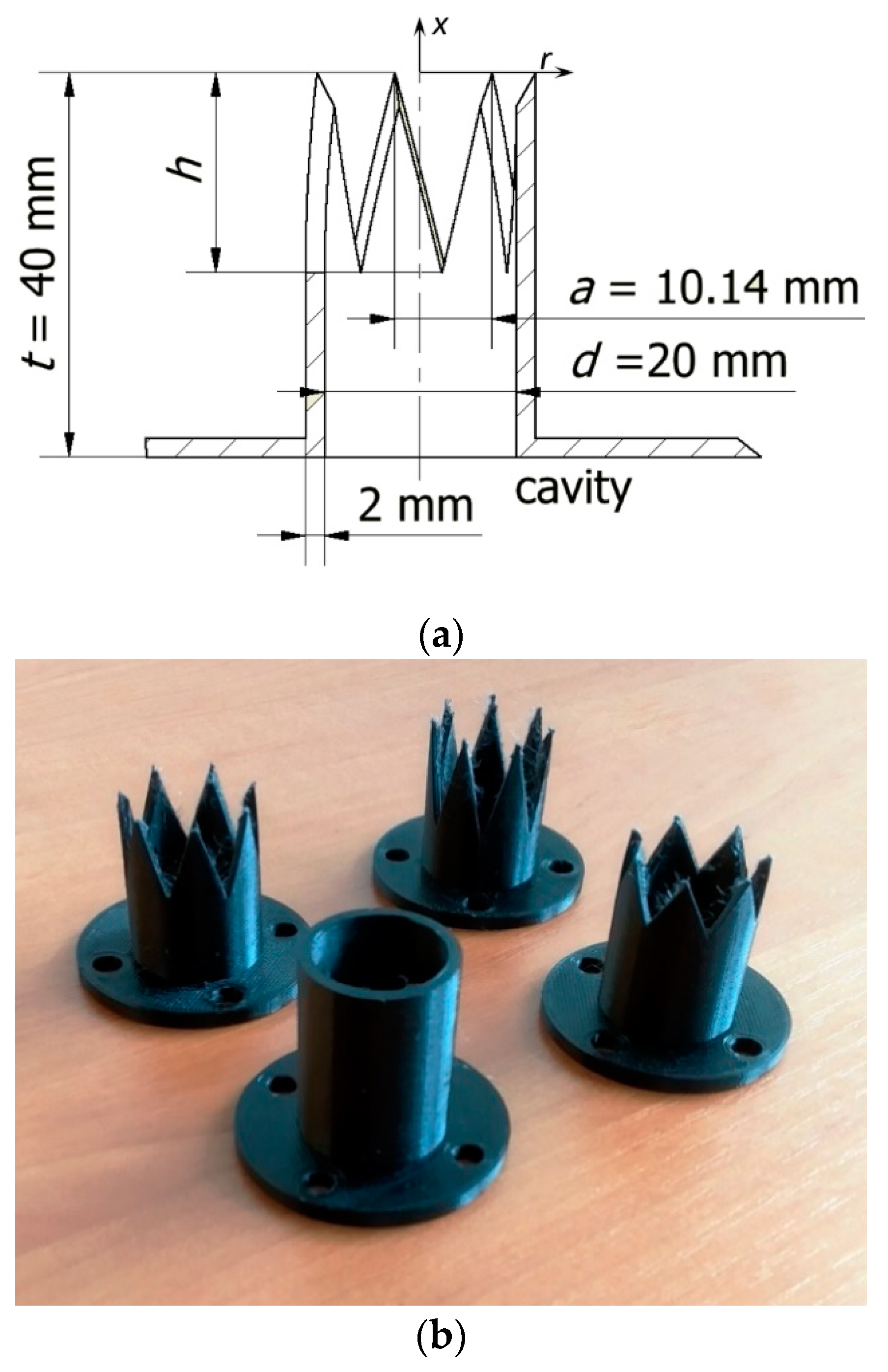
Figure 1. The parameters of the orifices (a) and the orifices printed using 3D technology before treatment (b).
Applsci 11 00652 g001
Figure 2. Scheme of the measurement stand with all the used equipment (a), photo of some parts of the measurement stand during velocity measurements (b), and a photo of the actuator during time mean reaction force measurements (c).
Applsci 11 00652 g002aApplsci 11 00652 g002b
Figure 3. The impedance of SJA as a function of frequency at real power p = 3 W.
Applsci 11 00652 g003
Figure 4. The local centerline time-averaged velocity (a) and local centerline maximum velocity (b) as a function of frequency at x/d = 0 and real power p = 3 W.
Applsci 11 00652 g004aApplsci 11 00652 g004b
Figure 5. The electrical efficiency of the SJA as a function of real power.
Applsci 11 00652 g005
Figure 6. Centerline velocity as a function of time at real power p = 3 W and x/d = 0 (a) or x/d = 3 (b).
Applsci 11 00652 g006
Figure 7. Centerline time-averaged velocity (a), centerline momentum velocity (b), centerline maximum velocity (c), and centerline turbulence intensity (d) as functions of ratio x/d at real power p = 3 W.
Applsci 11 00652 g007aApplsci 11 00652 g007b
Figure 8. SPL(A) of SJA at different power.
Applsci 11 00652 g008
Table 1. Specification of the synthetic jet actuators (SJAs).
Orifice Typed [mm] l [mm]Number of Chevrons a [mm]h [mm]fn [Hz]
Case 0Circle2040---36
Case 1Chevron2040710.40.52 d (10.4)38
Case 2Chevron2040710.40.76 d (15.6)40
Case 3Chevron2040710.41.04 d (20.8)42
Table 2. Measurement uncertainties.
NameRelative AccuracyAbsolute Accuracy
Power, P±2%
Force, F ±1 mN
Velocity, u (calibration accuracy)±2% (2.6–49 m/s)±0.1 m/s (<2.6 m/s)
Efficiency, η ±0.2%
SPL ±1.4 dB
Publisher’s Note: MDPI stays neutral with regard to jurisdictional claims in published maps and institutional affiliations.