Article

On the Optimal Synthesis of a Finger Rehabilitation Slider-Crank-Based Device with a Prescribed Real Trajectory: Motion Specifications and Design Process

by
Araceli Zapatero-Gutiérrez
1,*,
Eduardo Castillo-Castañeda
1 and
Med Amine Laribi
2
1
Centro de Investigación en Ciencia Aplicada y Tecnología Avanzada, Instituto Politécnico Nacional, Querétaro 76090, Mexico
2
Département Génie Mécanique et Systèmes Complexes, Institut PPRIME, Université de Poitiers, 86073 Poitiers, France
*
Author to whom correspondence should be addressed.
Appl. Sci. 2021, 11(2), 708; https://doi.org/10.3390/app11020708
Submission received: 6 October 2020 / Revised: 18 December 2020 / Accepted: 30 December 2020 / Published: 13 January 2021
(This article belongs to the Special Issue Modelling and Control of Mechatronic and Robotic Systems)

Abstract

:
This article discusses the mechanical redesign of a finger rehabilitation device based on a slider-crank mechanism. The redesign proposal is to obtain a smaller and more portable device that can recreate the motion trajectories of a finger. The real finger motion trajectories were recorded using a motion capture system. The article focused on the optimal synthesis of the rehabilitation device mechanism formulated as a classic trajectory generation problem. The proposed approach was combined with the recorded finger movements and solved using the genetic algorithm (GA) method. Optimization criteria and constraints were successively formulated and solved using a mono-objective function.

Graphical Abstract

1. Introduction

In traditional physical and occupational therapy, a therapist often assists a patient with a body movement that the patient cannot complete alone [1]. A rehabilitation program aims to help a patient recover the lost capabilities, resulting in greater patient independence [2]. Rehabilitation programs generally consist of three stages. They begin with passive movements, where the therapist applies an external force to the patient due to the lack of muscular activity [3], then the therapist continues with assistive exercises. The patient does most of the exercises, but needs partial assistance from the therapist to perform them correctly. Finally, in resistive exercises, the therapist provides little assistance to the patient who performs muscle contractions against an external resistance [4,5]. The exercises that contribute to the affected part’s mobility are mandatory, since it is crucial to avoid the harmful effects of immobilization [2].
This article focused on the rehabilitation of fingers. A finger is composed of a metacarpal and phalanges, two for the thumb and three for the other fingers. Every finger chain is articulated through the carpometacarpal joint (CM). At the distal direction, each metacarpal is articulated with the proximal phalanx through the metacarpophalangeal joint (MP). The thumb has one joint, the interphalangeal joint (IP), which is between the proximal and distal phalanges. The other four fingers have two joints: the proximal interphalangeal joint (PIP) and the distal interphalangeal joint (DIP). The first is located between the proximal and medial phalanges, and the second is located between the medial and distal phalanges [6], as shown in Figure 1.
Hands are the primary tool of human beings in any work environment, hence, they are exposed to all types of accidents or injuries due to diseases [7]. The use of robotic technology offers therapists with a tool to optimize the therapy process and the patient’s recovery. It has been proven to be safe, feasible, and effective for recovering the nervous and muscular systems, at least in patients with stroke [8,9,10,11,12,13].
The development of new technology in robotics for rehabilitation therapy can increase the overall time of therapy, increasing the total patients that are attended to and the quality of therapy with less supervision. There have been many developments around the world in which robots assist patients in performing the desired movements. The articles presented in [14,15,16] offer a complete classification of assistant robots, separated by the type of limb they assist.
There are many ways of classifying hand rehabilitation robots. One is based on the way motion is transmitted. The transmission allows the actuators to follow the desired hand trajectory. The transmission’s election depends on the trajectory that the hand is going to follow. Linkages and cables are common choices [17]. It is also possible to combine different types of transmissions, as in [18]. The screw-nut transmission transforms rotary motion into linear motion. It has a simple design that reduces cost and increases reliability. Another advantage is that the load can be raised by applying minimal effort while providing a precisely controlled linear motion. This main disadvantages of this type of transmission is its low efficiency and the rapid wear of the screw or the nut [19].
Hand rehabilitation robots are also classified based on the type of actuation (e.g., electric motor, pneumatic, hydraulic, and human muscle). The electric motor is the most widely used due to its reliability, availability, and precision [8]. Although pneumatic actuators require minor maintenance, the compressed air needs storage, influencing the device’s size and mobility. Hydraulic actuators have good performance because they can generate higher torque than other actuators. However, they require more infrastructure (the oil transmitting pipes and conduits) and space (for the actuation system). The human muscle, as a type of actuation, implies that the impaired hand needs to be activated by functional electrical stimulation to complete the motion [17].
A fundamental aspect of hand rehabilitation robotics is the device hardware design. The design requirements are different from the design of industrial robots. Hardware design involves considerations of the safety, portability, and flexibility of the mechanism to achieve effective rehabilitation for the patient [17].
Finger movement characteristics are essential in device design to specify patient safety. Large devices need hospitals to be equipped with ample rooms to place them. They are also expensive, which reduces the number of units purchased, leading to fewer patients who can use this technology [17].
Exoskeleton-type devices such as those presented in [20,21] require little space because they are mounted on the patient’s limb. Usually, the exoskeleton-type devices present more mechanically complex designs because the human joints must coincide with the exoskeleton’s joints. Furthermore, that can involve more than one degree of freedom (DOF) in the device. End-effector-type devices such as Amadeo [22], a leading finger rehabilitation device, features a simple and versatile design that easily adjusts to various hand dimensions, however, it needs a large work area to operate. The challenge with the end-effector devices is to make the designs as small as possible to obtain better portability.
From [14], only four devices focus on finger rehabilitation. In [15], seven are end-effector devices for finger rehabilitation, two of which are mentioned in [14]. In [16], they mentioned four systems assisting finger movements, two also mentioned in [14] and one in [15]. The end-effector developments are fewer in comparison with exoskeleton development, resulting in a potential field of research.
Optimization of mechanical and robotic designs is widely used for various applications such as serial manipulators and parallel robots [23,24,25]. However, it has also gained importance in assistive and rehabilitation devices as well as exoskeleton systems [26,27,28,29,30,31]. New optimization techniques have been sought to improve the dimensional characteristics and dynamic characteristics of the systems. One of the methods that has gained more attention in the optimization of mechanisms is the genetic algorithm. Due to the quality of the population produced, only the best individuals in each iteration are taken into account.
The authors present the optimization of an end-effector finger rehabilitation device that reproduces the individual trajectory of the fingers, which contributes to the first stage of rehabilitation (assistance for passive movements). Compared to other end-effector devices, the presented rehabilitation mechanism does not imitate the hand’s grasping functions.
Ensuring repetitive monitoring of the natural flexion–extension trajectory contributes to proper fit and alignment of the finger joints. The patient recovers the joint mobility simultaneously (MP, PIP, and DIP). Respecting each joint’s range of movement can contribute to the gross motor function and fine motor function. From a rehabilitation viewpoint, to improve the range of movement (ROM) at a joint, each joint must be moved through inside its ROM (expressed in degrees) at regular intervals. A continuous passive motion device (like a rehabilitation robot) facilitates the rapid recovery of the neuromuscular system by improving ROM [8,9,32,33].
The goal of this article is the proposal of an optimal redesign for a finger rehabilitation device. The work focused on proposing the optimal dimensions of the existing mechanism’s links, allowing for more accurate tracking of a trajectory compared to the existing prototype that uses a screw-nut transmission. Additionally, the original prototype’s links are too big concerning the end-effector trajectory’s size, which decreases the portability of the prototype.
The rest of this paper is structured as follows. Section 2 contains the finger rehabilitation device’s description and kinematic model and presents the characterization and analysis of the real finger trajectories, and finally, the optimization problem. Section 3 presents the optimization results, Section 4 presents the discussion, and, in Section 5, the conclusions are presented.

2. Materials and Methods

Figure 2 shows the redesign process for the previously mentioned finger rehabilitation prototype. The mechanism’s redesign focused on finding the optimal dimensions for a new mechanism (with the same architecture as the original) to replicate a real finger’s flexion–extension trajectory better.
The real trajectory analysis was carried out using a motion capture system, with the participation of a group of subjects. The hand’s digital reconstruction allowed for the measurement of the finger’s flexion–extension movement trajectories. The flexion–extension trajectory of a participant’s index finger was selected for comparison with the mechanism’s trajectory. This trajectory was chosen due to its large amplitude and equivalence characteristic regarding the other recorded finger motions. The genetic algorithm (GA) method found the dimensions that produced the minimum error between the mentioned trajectories.

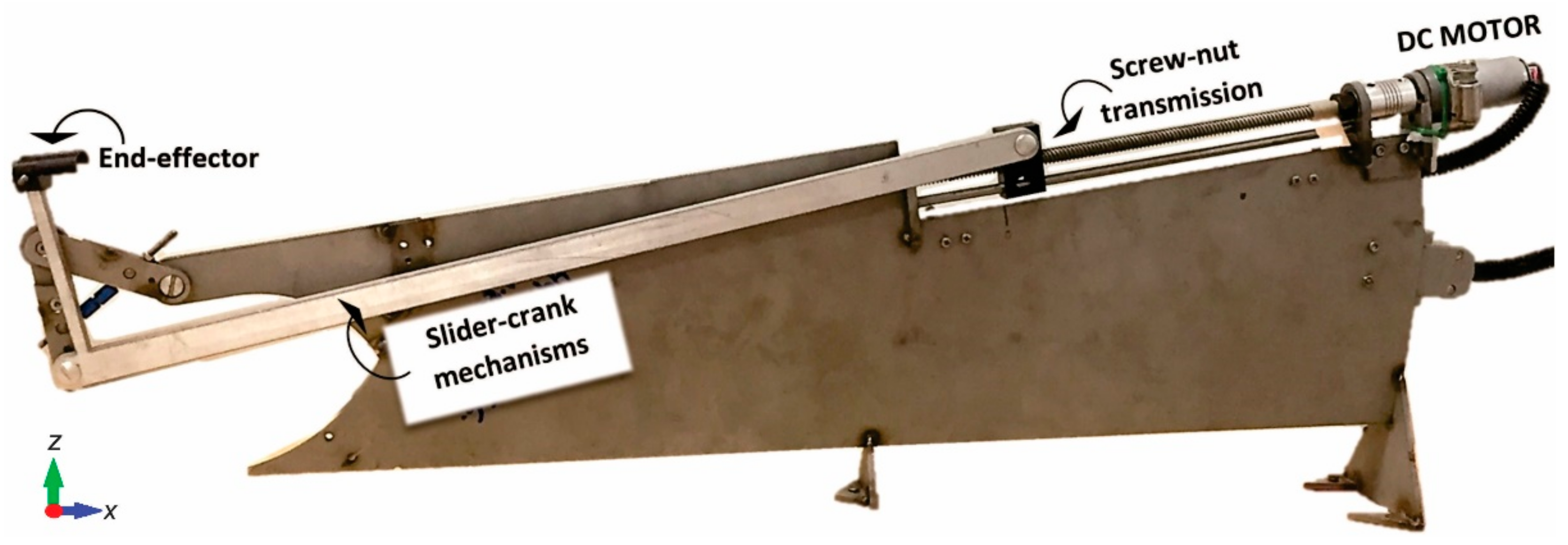
2.1. Finger Rehabilitation Device

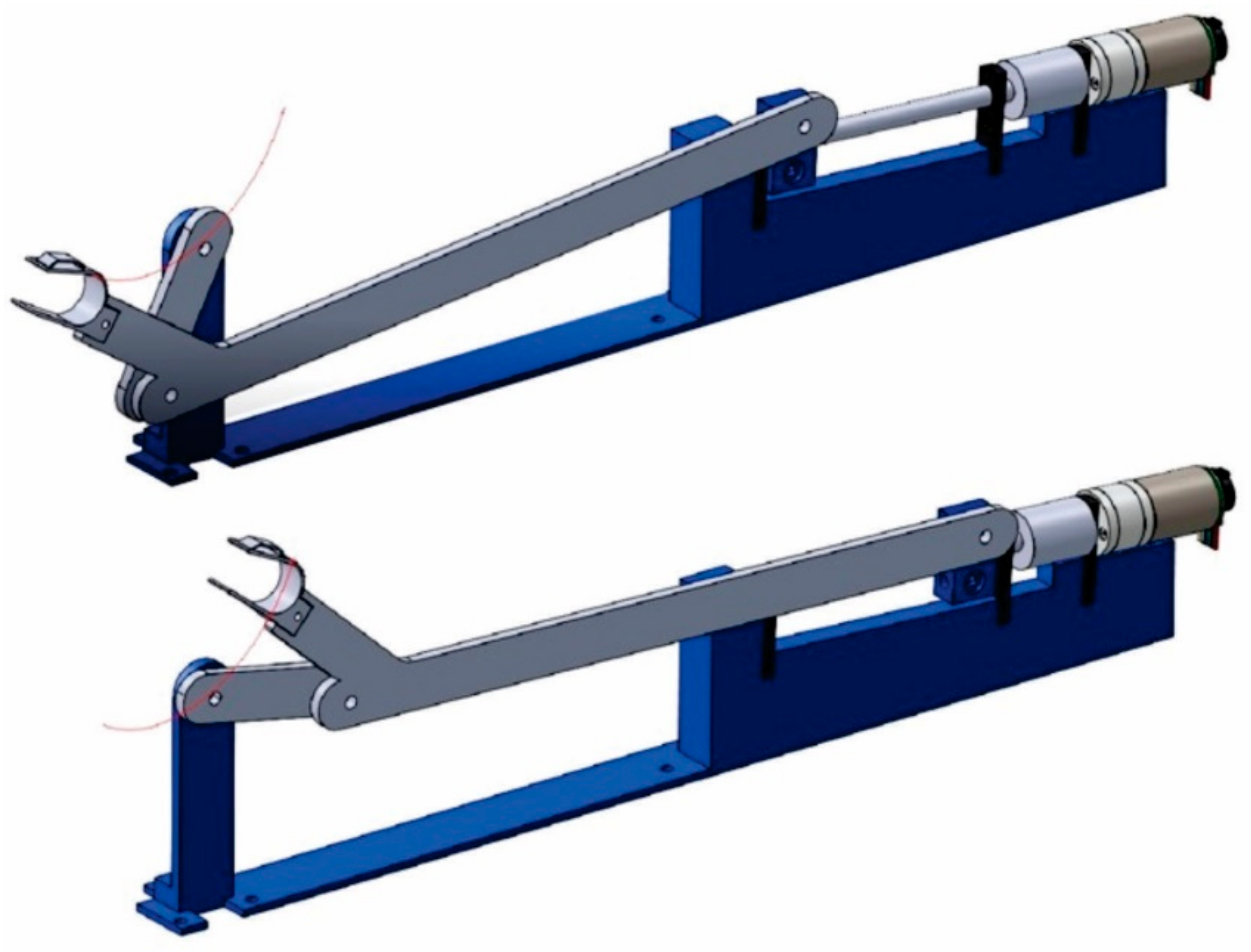
2.1.1. Existing Prototype

A prototype for assisting flexion–extension movements from the index to small fingers was proposed in 2016 [34]. The prototype consisted of four parallel mounted slider-crank mechanisms (one for each finger), driven by a direct current (DC) motor and a screw-nut transmission, as shown in Figure 3. The end-effector, located in the coupler link, was the contact point between the prototype and the fingertip. The fingertip was attached to the end-effector using an articulated thimble placed at the extremity and was fixed with adhesive fabric. Figure 4 shows how the arm and fingertip are positioned on the mechanism.
The patient’s forearm was placed in a support that could be adjusted in the x and z plane. The upper part of the support had an integrated universal wrist–forearm splint. The patient inserted their arm into the splint and adjusted with Velcro straps, which allowed the forearm, wrist, and palm to be entirely fixed on the surface of the support.
The end-effector produces an arc segment, as shown in Figure 5, close to an elliptical trajectory. The end-effector’s trajectory aims to closely follow the finger’s flexion–extension movement’s natural trajectory, which has been studied by several authors [35,36,37]. This end-effector’s trajectory is the defining characteristic of this prototype; other well-known finger rehabilitation devices like Amadeo [22] use linear trajectories [38,39,40]. This remarkable difference is because the presented rehabilitation mechanism does not imitate the hand’s grasping functions.
The elliptical trajectory was compared with the end-effector mechanism’s trajectory to propose an optimized size for the prototype. However, this research did not involve mechanical changes or performance improvements to the transmission.
The prototype’s original dimensions were obtained using three points of the elliptical trajectory described in the previous section; the full prototype design can be consulted in detail in [34]. The original prototype’s elliptical trajectory tried to emulate the natural flexion–extension movement. However, its design did not involve real flexion–extension trajectories. In addition, given its size, it cannot be easily transported. It is essential to ensure that the prototype’s end-effector can reproduce real trajectories with minimum error to achieve better rehabilitation results and reducing its dimensions will improve its portability.

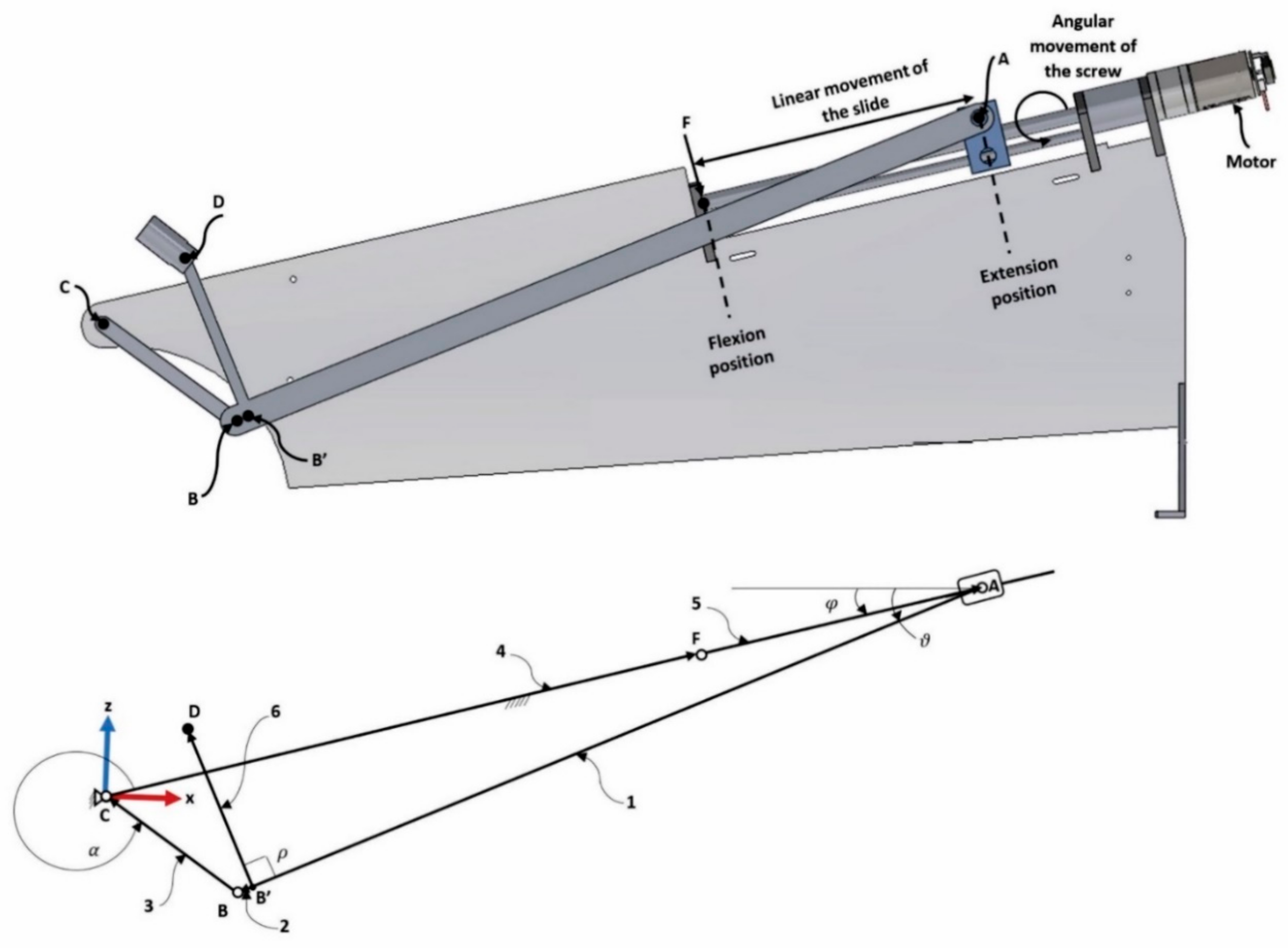
2.1.2. Architecture and Kinematic Model

Since the four mechanisms are similar, it is sufficient to only analyze one of them. Figure 6 shows the computer-aided design (CAD) of one of the mechanisms and its vector representation. Vector position 1 and 3 correspond to the distance between the points A to B and B to C, respectively. The DC motor provides the angular movement that is converted into a linear movement through the screw-nut transmission. This linear movement is limited by the minimum and maximum position of the flexion and extension points. The kinematics analysis is presented in detail in [41]; for the analytical purposes of the mechanism’s redesign, a tag was assigned to every vector, as shown in Table 1.
Vector 4 represents the physical distance between points C and F. Point F represents the minimum position of flexion movement. Point D is the contact point between the patient and the device and describes the elliptical trajectory that was mentioned before. Point D could be considered as a rigid body attached to the AB link and has an angle ρ with respect to AB. Angle φ represents the inclination angle of the mechanism. In the original prototype, ρ = 90 degrees and φ = 10 degrees.
Considering Figure 6, Equation (1) defines point D’s position coordinates, which is the end-effector’s point that describes the elliptical trajectory. Vector 5 (Equation (5)) is defined by a function that includes the length of vector 4 and the distance C i between the minimum and maximum position values, corresponding to the flexion and extension points. The distance C i is defined by Equation (6) and can be used for the optimization process. Vector 4 of the original prototype was fixed to 344 mm, while the distance C i went from 0 to 125 mm. Vectors 2 and 6 are the distances between B to B’ and B to D, respectively.
From Equation (6), C 0 represents the minimum value of C i and C m represents the maximal value. C m is defined by Equation (7), where d m is the distance the slider needs to generate the desired trajectory. d m is defined by the sum of the minimal value and the distance between the initial and final points of the trajectory.
D = D x D z = b   cos α + d   cos ϑ + e cos β b   sin α + d   sin ϑ + e sin β ,
where
α = 2   π a r c cos a 2 c 2 b 2 2 b c + φ ,
  ϑ = φ + a r c cos b 2 c 2 a 2 2 a c ,  
  β = ϑ + ρ ,  
  c = f + C i .  
The solution for this equation exists if and only if:
a b s a 2 c 2 b 2 2 b c < 1   and   abs b 2 c 2 a 2 2 a c < 1   C i = j = C 0 C m j ,
  C m = d m + C 0 .  

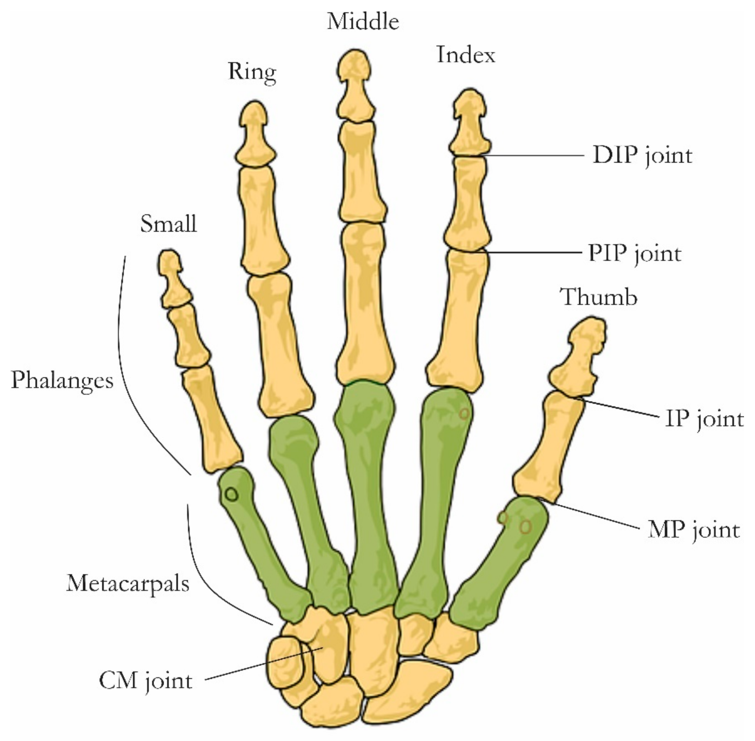
2.2. Finger Real Motion

2.2.1. Experimental Setup

To propose an improvement to the actual prototype, we performed several experiments to obtain real curves for the fingers’ flexion–extension movements. These real curves were used to evaluate the accuracy of the elliptical trajectory proposed in the original prototype. The finger movements were recorded using the motion capture system Qualisys Track Manager (v2018, Qualisys, Göteborg, Sweden, 2018), which was used to process those records. A set of coordinates for each marker as a function of time was defined to analyze the data. Mokka (v0.6.2, BTK, 2019) and MATLAB software (v2018, MathWorks, Meudon, France, 2018) were used.
The system was calibrated using a reference frame located in the corner on a flat surface. The volunteer placed their forearm, as shown in Figure 7. We recorded the flexion–extension movements from the index to small fingers. A total of six volunteers were involved in the experimentation, both men and women, in the age range of 25 to 40 years old without any finger injury.
A set of 21 markers was used and installed on the right hand of each volunteer. Table 2 describes each marker’s location and the label that was used to reconstruct the hand in digital form. The digital reconstruction of the hand is shown in Figure 8. The digital reconstruction was based on marker locations following the anatomy of the subject.
Each volunteer’s forearm was placed on a flat surface, with the palm perpendicular to the surface and their fingers in the extended position. The subjects were asked to close and then open their fist, as shown in Figure 9, and to repeat the exercise 10 times. The plane where the flexion–extension movements from the index to small fingers were performed was perpendicular to the plane where the thumb’s flexion–extension movements are performed.
The existing prototype was designed only for the flexion–extension movements from the index to small fingers and considered only the trajectory of the distal phalanx; for this reason, only the marker placed in the distal phalanx for these fingers (I1, M1, R1, and S1) was analyzed.

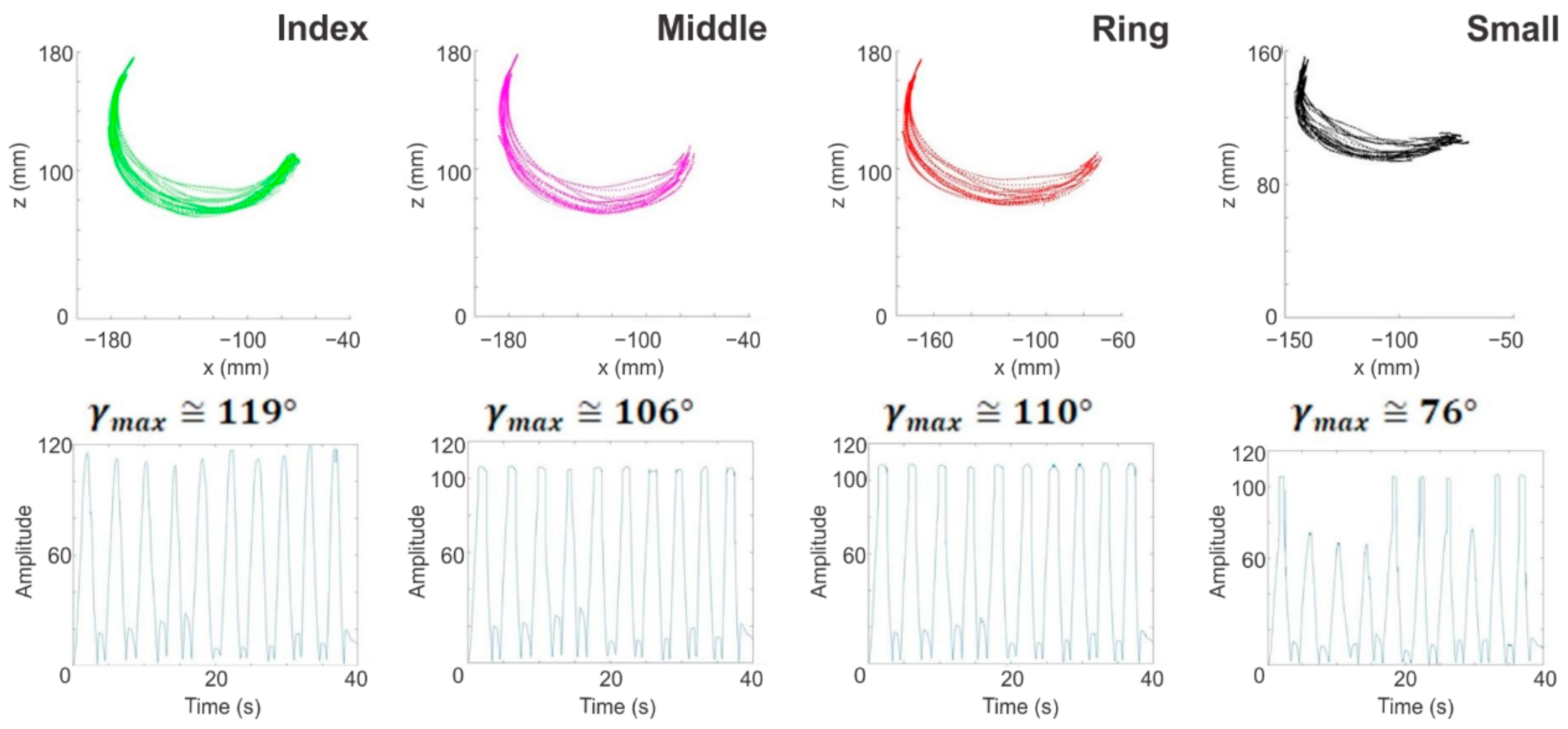
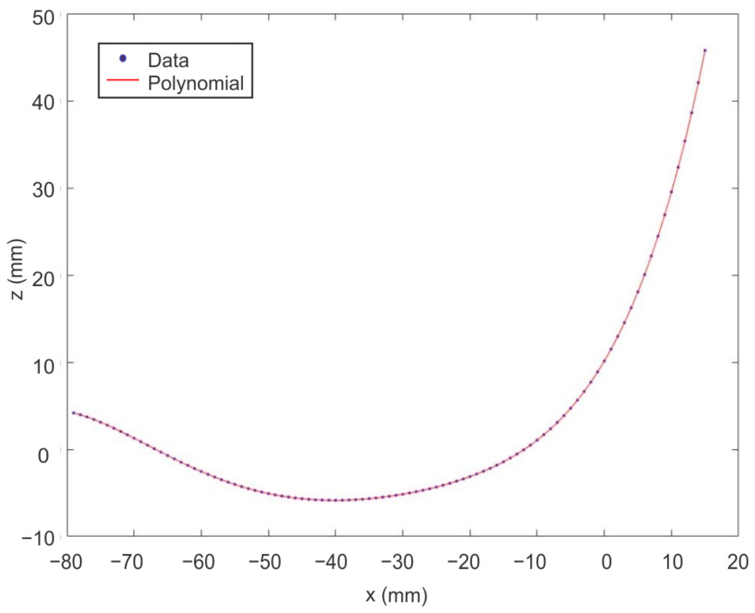
2.2.2. Results of the Analysis of the Fingers Real Motion

The recorded gesture focused on the flexion–extension movement leading to the fingertip trajectory. This finger movement occurs in the finger plane, which is normal to all joint axes. Consequently, the fingertip trajectory were defined only by the x and z coordinates (as shown in Figure 10). A series of three-dimensional curves, as shown in Figure 11, was obtained using the flexion–extension movement in the xyz space, which corresponded to the recorded motion for a volunteer’s index finger.
All subjects were asked to move their finger with a fixed abduction–adduction. Despite this virtual constraint and the low-speed exercise, the obtained fingertip trajectory presented a reduced variation along the y-axes, probed through principal component analysis (PCA). The PCA reduces the dimensionality of a dataset of interrelated variables while retaining the dataset’s variation. A new set of variables is generated, a linear combination of the original variables. This new set of variables is called the principal components [42].
The PCA indicates which variable is the most valuable for clustering the data. In this article, the original set of variables are the xyz coordinates of the n point of the flexion–extension movement, which means that three principals components exist. The principal component is obtained by calculating the average values for all the variables, as shown in Equation (8). The original variables are defined as p-dimensional vectors that need to be projected onto a q-dimensional subspace.
x ¯ = i = 1 n x i n y ¯ = i = 1 n y i n z ¯ = i = 1 n z i n
The PCA identifies the directions (principal components) along which the variation in the data is maximal. The direction of PC1 represents the most significant variation among the data, PC2 is the second most important direction and is uncorrelated to PC1 and PC3. PC3 represents the less important direction, also uncorrelated with the other principal components. Principal components are normalized eigenvectors of the covariance matrix. These are ordered according to how much of the variation present in the data they contain. The dimensionality of the three-dimensional data can be reduced to two-dimensional data using the first two principal components [43,44].
Table 3 shows the covariance data matrix’s eigenvalues and the percentage of each principal component total variance. The eigenvalues measure the amount of variation retained by each principal component [44].
As can be observed in Table 3, the first two components explained 99.39% of all variability, as shown in Figure 12. This proves that the y-axis presents a reduced variation in the flexion–extension movement of the fingers. Due to this, one can conclude that the flexion–extension movement can be assumed in the xz plane. The abduction–adduction movement of the finger was not considered.
The finger motion, from the index to small, was analyzed. A similarity was observed between all fingertip trajectories, as shown in Figure 13a. An example of graphs obtained for all fingers of one subject is depicted in Figure 13b. The left side of Figure 14 shows all the trajectories recorded in the xyz space. The right side shows one movement in the xz plane to improve the visualization of each finger’s trajectories.
Aside from the trajectories, we computed the range of motion of every finger. We defined the u f i vector in the finger plane, where f ϵ I , F , R , S corresponds to index ( I ), Middle ( M ), Ring ( R ), and Small ( S ), and the index i corresponds to the frame number from 1 (initial position) to N (last position). The computed vector corresponds to the subtraction between the xz position of the tip marker (I1, M1, R1, S1) and the xz position of the MCP marker (I4, M4, R4, S4), as defined in Equation (9).
Finger     Vector Index     u I i = I 1 I 4 ,   Middle     u M i = M 1 M 4 ,   Ring     u R i = R 1 R 4 ,   Small     u P i   = S 1 S 4 .  
Then, we defined u ^ f i as the normal vector of u f i as Equation (10) shows. The vector w f represents the dot product between the initial position and the i t h position, in order to compute the angle between these normal vectors, which is expressed in Equation (11).
u ^ f = u f u f   , w f = j = 1 j = 2 v f 1 · v f j j = 1 j = K v f 1 · v f j j = 1 j = N v f 1 · v f j ,
  γ i   = a r c cos w f .
Figure 15 shows the trajectories of one subject from the index to small in the xz plane and the maximum and minimum angle of each finger’s movement. The maximum angle for the small finger was chosen as γ m a x 76 ° because several points were outside the trajectory and represented false measurements (Figure 13).
As can be observed from Figure 14, the trajectories for the different fingers were similar in shape but with different maximum angle ( γ m a x ) amplitudes. Table 4 shows the values of the angles of movement among the volunteers after several tests.
To conclude this section on real finger motion. Figure 15a simultaneously illustrates the original prototype trajectory and index finger trajectory from one subject, which was chosen as the recorded real trajectory. The real finger trajectory did not have a regular elliptical shape, and it seems to have a more closed shape. In contrast, when the end-effector’s prototype trajectory maintained an elliptical behavior, an offset between the two trajectories was noted.
It seems feasible that the prototype trajectory follows the real trajectory more closely. Figure 15b shows the quadratic error between the two trajectories. It can be noticed that this error was not negligible and the error was used as an optimization criterion. The end-effector, located at the fingertip, was required to follow a specified curve with a minimum error computed between the obtained and desired trajectories.

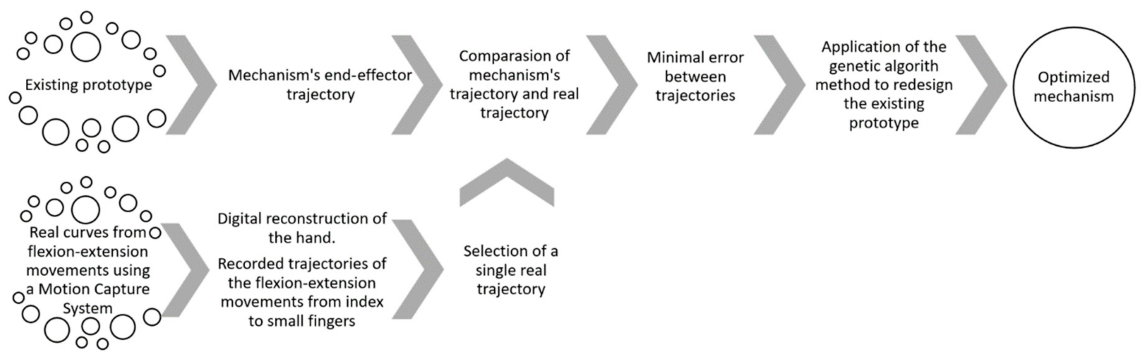
2.3. Synthesis Problem

Three types of formulation applied to mechanism synthesis problems can be found in the literature: function generation, trajectory generation, and body guidance [45]. This article focused on trajectory generation based on an optimization process. An optimal mechanism to generate the desired trajectory followed by the fingertip was found. The data from the real finger trajectory, described in the previous section, was used in the computation of the objective function. This allowed us to find the optimal parameter of the solution to reconfigure the existing rehabilitation mechanism. The optimization problem was solved using the genetic algorithm method.

2.3.1. Formulation of the Problem

The optimization problem can be established as the minimization of the error function E F , which is the sum of the square distance between the ith recorded position ( R x i : N ,   R z i : N ) and the coordinates of point D of the mechanism ( D x i : N , D z i : N ). The error function is expressed by Equation (12). This point corresponds to the end-effector of the slider-crank mechanism. Equation (13) defines the design vector F , which contains the set of variables that should be computed during the optimization procedure.
f m represents the individual in the genetic algorithm; H f   defines the lower and upper boundaries for each of the design variables; and g m 1 and g m 2 are constraints applied to the mechanism.
E F   = 1 N   i = 1 N D x i R x i 2 + D z i R z i 2 .
The optimization synthesis problem was formulated as follows with m = 10 parameters for a chosen objective function E F :
Minimize   E F ,
Subject to:
F =   f 1 , , f m ,   m = 10 ,   f m   ϵ   H f =   f m m i n , f m m a x g m 1 F 1 , g m 2 F 1 ,
where H f = f m m i n , f m m a x   is the bounding interval for each parameter of vector F . The parameters of vector F are defined in Table 5; most of the parameters are defined in the kinematic section. The variables x t and y t represent an offset applied to the real trajectory to relocate it to the same work area of the existing mechanism, allowing for a comparison of both trajectories.
The kinematic model of the slider-crank mechanism was defined by Equations (1)–(7) in previous sections. Equation (14) defines the inequality constraints to guarantee a feasible solution of the optimization problem and comes from the closed-loop equations. The constraints g m 1 and g m 2 are defined in the following formulation:
g m 1 =   a 2 c 2 b 2 2 b c   1 , g m 2 =   b 2 c 2 a 2 2 a c   1 .

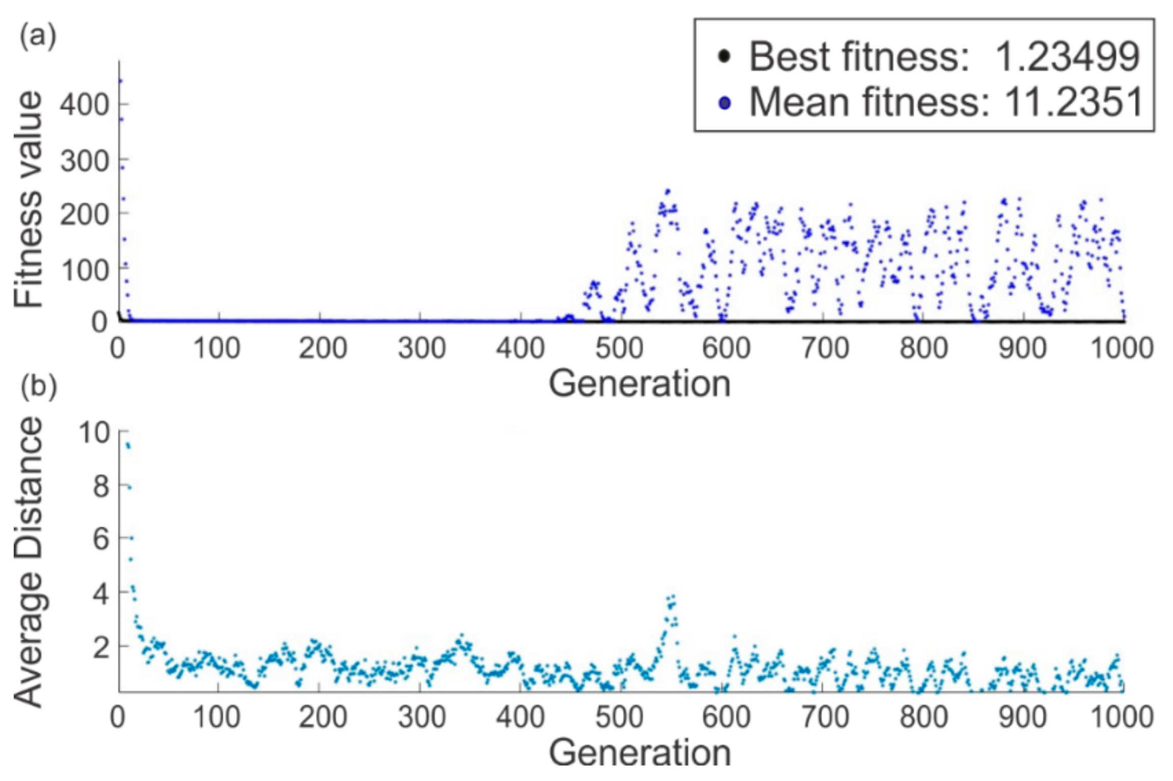
2.3.2. Genetic Algorithm Method Implementation and Curves Enhancement

The genetic algorithm (GA) is a probabilistic technique based on the evolutionary theory of natural selection that uses a population of designs rather than a single design at a time. The GA generates a population of individuals at each iteration. These individuals are a combination of the previous population’s characteristics (called parents). However, they can also present some mutations in their characteristics. Only the best individuals in the population are used to create a new generation, which allows the approach toward an optimal solution. The GA operators select the next population by computation using a random number generator.
Nevertheless, this algorithm presents a limited accuracy of the final solution. A large number of iterations is needed to obtain a solution [46,47]. Figure 16 shows the scheme of the GA method applied to the problem of mechanism synthesis.
The main goal of the GA is to identify the best value of the design vector F , which contains all the parameters that describe the mechanism. Each design vector is called an individual.
The design vector is evaluated through the fitness function that quantifies the result of the individual’s parameters. The best fitness value for a population is the smallest fitness value for any individual in the population [47]. In order to obtain better results in the GA implementation, it is recommended that the input trajectory presents the same step between points. A polynomial fitting method is used and included in the optimal synthesis process.
In order to obtain a uniformly distributed trajectory, the desired trajectory was approximated using a polynomial fitting method, as shown in Figure 17 and given by Equation (15), where a 0 , a 1 , a 2 , a 3 , a 4 , and a 5 are the fitting parameters. An example, based on the index finger’s trajectory of subject three, is given in this section. The numerical values of the fitting parameters are defined in Table 6.
P x   = a 0 + a 1 x + a 2 x 2 + a 3 x 3 + a 4 x 4 + a 5 x 5
A population of 1000 individuals was used, which was manipulated through 1000 generations ( G m a x ). The objective function was evaluated 1 × 10⁶ times. The algorithm was allowed to select the design parameter values in the interval stated in Table 7. This interval corresponds to the function H f . The best fitness value was obtained in the last generation. This solution represents an optimal solution for the mechanism.

3. Improvement of the Existing Mechanism and Results

Figure 18 shows the evolution of the objective function along with the generations. The figure shows the convergence between the best fitness and average fitness values found during the GA iterations. The upper plot (Figure 18a) displays the best score value (black dots) and the mean score (blue dots) versus generation. It showed little progress in lowering the fitness value. The best individual’s fitness value remained small throughout the generations. The lower plot (Figure 18b) shows the average distance between individuals at each generation and represents the population’s diversity.
Table 8 shows the comparison between the optimal solution provided for the GA and the prototype’s real dimensions. The GA provided a smaller mechanism through the best values of the seven parameters representing the mechanism’s dimensions. The optimized mechanism followed the desired trajectory with a minimal error of 1.62 mm. Furthermore, it shows the distance the slider needs to move to reproduce the desired trajectory, which is generally proposed by the designer.
Figure 19 shows the trajectories among the real data, the polynomial form, and the GA. It can be noticed that even though the error was minimal at the end of the trajectory, the mechanism was unable to reach the last point. This is logical considering the configuration of a slider-crank mechanism, derived from the fact that the slider-crank mechanism cannot close the path of the end-effector even when the distance traveled is increased.
Figure 20 shows how the error between the trajectories was dramatically reduced when implementing the GA method. Figure 20a shows the error between the real trajectory recorded by the motion capture system and the end-effector’s trajectory of the existing prototype (this figure has already been presented at the end of Section 2.2.2). Figure 20b shows the error between the real recorded trajectory and the end-effector’s trajectory obtained with the GA method.
To validate the quality of the convergence, Figure 21 shows the histogram of the last population. The histogram shows the distribution of the last population in the upper and lower limits of each individual. The frequency represents the number of times that an individual is presented in each limit. The cumulative frequency (expressed in percentage) is the sum of the absolute frequencies and indicates the number of individuals in each interval.
Concerning the angle of motion γ , a difference of 2.5 degrees was found between the real trajectory and the end-effector’s trajectory of the new mechanism (as is shown in Figure 22).
Improvement in size over the existing mechanism can be made. Both mechanisms were drawn in extreme positions (corresponding to flexion and extension positions), as shown in Figure 23.
In Figure 24, a CAD proposal for the new mechanism and the desired curve is presented. Figure 25 shows the redesign of the four fingers. The distance between mechanisms, measured from the point D of every mechanism, was 28 mm.

4. Discussion

The shape and amplitude of the flexion–extension trajectory had to be considered to design a better mechanism. This is because the mechanism must be able to adjust the range of motion for different flexion–extension amplitudes. Since the optimized mechanism’s configuration is an end-effector, it allows for the extrapolation of the result obtained for use with different subjects. The flexion–extension movement is not affected since the trace is at the fingertip.
Using the PCA technique, it was possible to transform the real flexion–extension movement from the xyz space to the xz plane. This simplification of the workspace simplifies the design of the mechanism and does not compromise the trajectory’s shape. The use of PCA to derive postural synergies has mainly been used to study the hand’s different kinematic configurations during the grasping and manipulation processes [48,49,50,51]. This article did not use PCA to reduce kinematic configurations during grasping. It consisted of verifying that the fingers’ flexion–extension movement in space could be simplified to a movement in a plane, resulting in a design simplification of the mechanisms that tried to reproduce this trajectory.
The rehabilitation mechanism presented did not seek to emulate the hand’s grip functions, but sought to intervene during the first stage of rehabilitation where the physiotherapist repeatedly and independently mobilized the patient’s fingers to reduce stiffness and expand the range of motion.
Regarding GA performance, the low measure of population diversity ensured that the best individuals were close to the optimal solution. The number of generations and the population size used also contributed to finding the best solution. The algorithm converges due to the average distance between individuals in terms of fitness value decreasing as generations passed. The capability to converge to an optimal solution means that the objective function was successfully minimized based on the error between the real finger trajectory and the mechanism’s trajectory. The error between the original mechanism’s trajectories and the real finger increased as the flexion–extension movement was performed. In contrast, this error decreased with the dimensions of the mechanism obtained through the GA.
The amplitude of the trajectory γ of the optimal design had a difference of almost 2.5 degrees, compared with the real trajectory considered for the optimization process. It is assumed that the difference between trajectories is representative of the mechanism’s performance. As can be observed in Figure 23, the mechanism trajectory followed the real trajectory very closely. This can be an indicator of mobility recovery in the patient because as the patient has an improvement in the rehabilitation process, the amplitude of the trajectory will increase. It is important to point out that clinical tests are required to evaluate the device’s feasibility and potential benefits.
Even though the design results for a slider-crank-based rehabilitation device are promising, this type of mechanism cannot reproduce more closed trajectories. This means that for a certain number of patients, the device cannot meet successful rehabilitation criteria.
One of the issues addressed and successfully handled in this work is that the design vector includes the geometric parameters of the slider-crank mechanism and the distance that the slider needs to displace to generate the desired trajectory. This point is significant because this distance is the input of the mechanism and traditionally considered as known. For example, this distance was fixed in the existing prototype as a consideration of the designer at 125 mm [34].
The mechanism design was limited only to physical therapy because it only helps the patient improve flexion–extension movements. Occupational therapy requires a more complex mechanical design that allows for different finger trajectories to be performed as well as some virtual interaction schemes that simulate daily life activities.
The prototype proposed needs less workspace to operate than Amadeo [22], one of the available commercial finger rehabilitation devices. The optimized prototype is expected to occupy a volume of 0.09 m3 against the 3 m3 that Amadeo needs [52]. The optimized prototype pretends to improve every joint’s ROM using a near trajectory to the natural flexion–extension trajectory regarding Amadeo’s end-effector linear trajectories.
Another available commercial finger rehabilitation device is Digitrainer. The workspace of the DigiTrainer is about 0.017 m3. However, its configuration uses end-effector rollers that make contact across the entire surface of the finger [53], which can be uncomfortable if the patient has sensitive skin. The optimized prototype presented in this paper avoids sensitive skin problems as the contact is only in the fingertip.

5. Conclusions

This article proposed an improvement of a finger rehabilitation device based on a real trajectory. The slider-crank mechanism is one of the most studied in the theory of mechanisms due to its simplicity, efficiency, and suitability for many applications in which it can be used. The significance of the slider-crank mechanism presented in this article is that the mono-actuator action is applied toward a medical solution. The presented mechanism is a novel finger flexion–extension rehabilitation device.
Its synthesis requires a careful analysis of the natural flexion–extension trajectory of the fingers. The focus of the optimization problem was the mono-objective formulation to minimize the error between the real trajectory and the mechanism’s trajectory. This optimal solution allows the mechanism to follow a real trajectory more closely. The optimal dimensions of the finger rehabilitation prototype presented in this article allow for the optimization of the therapist’s workspace without compromising the end-effector trajectory’s performance.
An experimental setup was performed to obtain real trajectories using a motion capture system and healthy volunteers. The real fingertip trajectory was used as an input to the synthesis problem of the slider-crank mechanism. The presented method is still available for all other subjects and fingers and is also based on the recorded real trajectories.
The kinematic equations were reformulated to be included in the GA method. Using other synthesis methods for this application would mean omitting the design’s original purpose: finger rehabilitation. The GA fitness function calculates the distance that the slider must travel to generate a flexion–extension path in the end-effector. This characteristic is a peculiarity of this function because GA proposes the optimal distance between the maximal flexion position and maximal extension position and does not need to be defined by the designer.
Future work will focus on a new topology of mechanisms with more degrees of freedom, which could describe more complex shapes of trajectories. In the next work, the study of transmitted forces on the fingers will also be examined. The idea of studying the behavior of the exchange forces between the patient and the device is to develop a more appropriate control strategy that could address the differences in the fingers’ capabilities.
This is an important point because, at this stage, the mechanism can only reproduce the flexion–extension trajectory but cannot deal with situations such as the pain experienced by the patient when trying to complete the movements. A suitable rehabilitation device must consider the relationship between the force provided by the mechanism and finger movement.

Author Contributions

Conceptualization, M.A.L., E.C.C. and A.Z.G.; Methodology, A.Z.G. and M.A.L.; Software, M.A.L. and A.Z.G.; Validation, A.Z.G. and M.A.L.; Formal analysis, A.Z.G., M.A.L., and E.C.C.; Investigation, A.Z.G., M.A.L., and E.C.C.; Resources, M.A.L.; Data curation: A.Z.G., M.A.L., and E.C.C.; Writing-original draft preparation, A.Z.G.; Writing-review and editing: M.A.L., E.C.C., and A.Z.G.; Visualization, M.A.L., E.C.C., and A.Z.G.; Supervision, M.A.L. and E.C.C.; Project administration, M.A.L. and E.C.C.; Funding acquisition, M.A.L. and E.C.C. All authors have read and agreed to the published version of the manuscript.

Funding

This research received no external funding.

Institutional Review Board Statement

Ethical review and approval were waived for this study due to non-invasive experimentation being performed.

Informed Consent Statement

Verbal informed consent was obtained from all subjects involved in the study due to non-invasive experimentation being performed.

Data Availability Statement

Data sharing is not applicable to this article.

Acknowledgments

The authors are grateful to the University of Poitiers, France and the Instituto Politécnico Nacional (IPN), México. As well as the Consejo Nacional de Ciencia y Tecnología (CONACYT), México, for the facilities provided for this research.

Conflicts of Interest

The authors declare no conflict of interest.

References

  1. Cooper, R.A.; Dicianno, B.E.; Brewer, B.; LoPresti, E.; Ding, D.; Simpson, R.; Grindle, G.; Wang, H. A Perspective on Intelligent Devices and Environments in Medical Rehabilitation. Med. Eng. Phys. 2008, 30, 1387–1398. [Google Scholar] [CrossRef] [PubMed]
  2. Freis, N.E. La Rehabilitación En Ortopedia y Traumatología Parte, I. Rev. Asoc. Argentina Ortop. Traumatol. 2006, 71, 272–277. (In Spanish) [Google Scholar] [CrossRef]
  3. Freis, N.E.; Heinrichs, K. La Rehabilitación En Ortopedia y Traumatología Parte II. Rev. Asoc. Argentina Ortop. Traumatol. 2006, 71, 362–368. (In Spanish) [Google Scholar]
  4. Dutton, M. Range of Motion. In Introduction to Physical Therapy and Patient Skills; McGraw-Hill Education: New York, NY, USA, 2014. [Google Scholar]
  5. Physical Rehabilitation. Available online: https://www.martinpetkov.com/your-opportunity/physical-rehabilitation (accessed on 9 December 2020).
  6. Borobia, C. Valoración Del Daño Corporal. Medicina de Los Seguros. Miembro Superior; Valoración del Daño Corporal; Masson Elsevier: Barcelona, Spain, 2006; Available online: https://books.google.com.mx/books?id=OClwWvys-ysC (accessed on 19 April 2020).
  7. Kim, Y.H.; Choi, J.H.; Chung, Y.K.; Kim, S.W.; Kim, J. Epidemiologic Study of Hand and Upper Extremity Injuries by Power Tools. Arch. Plast. Surg. 2019, 46, 63–68. [Google Scholar] [CrossRef] [Green Version]
  8. Krebs, H.I.; Edwards, D.; Hogan, N. Forging Mens et Manus: The MIT Robotic Therapy; Reinkensmeyer, D.J., Dietz, V., Eds.; Springer International Publishing: Berlin, Germany, 2016; pp. 333–350. [Google Scholar] [CrossRef]
  9. Burgar, C.G.; Lum, P.S.; Shor, P.C.; Machiel Van der Loos, H.F. Development of Robots for Rehabilitation Therapy: The Palo Alto VA/Stanford Experience. J. Rehabil. Res. Dev. 2000, 37, 663–673. [Google Scholar]
  10. Fasoli, S.E.; Krebs, H.I.; Stein, J.; Frontera, W.R.; Hogan, N. Effects of Robotic Therapy on Motor Impairment and Recovery in Chronic Stroke. Arch. Phys. Med. Rehabil. 2003, 84, 477–482. [Google Scholar] [CrossRef] [Green Version]
  11. Krebs, H.I.; Volpe, B.T.; Williams, D.; Celestino, J.; Charles, S.K.; Lynch, D.; Hogan, N. Robot-Aided Neurorehabilitation: A Robot for Wrist Rehabilitation. IEEE Trans. Neural Syst. Rehabil. Eng. 2007, 15, 327–335. [Google Scholar] [CrossRef] [Green Version]
  12. Volpe, B.T.; Ferraro, M.; Krebs, H.I.; Hogan, N. Robotics in the Rehabilitation Treatment of Patients with Stroke. Curr. Atheroscler. Rep. 2002, 4, 270–276. [Google Scholar] [CrossRef]
  13. Fasoli, S.E.; Adans-Dester, C.P. A Paradigm Shift: Rehabilitation Robotics, Cognitive Skills Training, and Function after Stroke. Front. Neurol. 2019, 10, 1–10. [Google Scholar] [CrossRef] [Green Version]
  14. Rodríguez-Prunotto, L.; Cano-De La Cuerda, R.; Cuesta-Gómez, A.; Alguacil-Diego, I.M.; Molina-Rueda, F. Terapia Robótica Para La Rehabilitación Del Miembro Superior En Patología Neurológica. Rehabilitacion 2014, 48, 104–128. [Google Scholar] [CrossRef]
  15. Aggogeri, F.; Mikolajczyk, T.; Kane, J.O. Robotics for Rehabilitation of Hand Movement in Stroke Survivors. Adv. Mech. Eng. 2019, 11, 1–14. [Google Scholar] [CrossRef]
  16. Maciejasz, P.; Eschweiler, J.; Gerlach-hahn, K.; Jansen-troy, A.; Leonhardt, S. A Survey on Robotic Devices for Upper Limb Rehabilitation. J. Neuroeng. Rehabil. 2014, 11, 1–29. [Google Scholar] [CrossRef] [PubMed] [Green Version]
  17. Yue, Z.; Zhang, X.; Wang, J. Hand Rehabilitation Robotics on Poststroke Motor Recovery. Behav. Neurol. 2017, 2017, 3908135. [Google Scholar] [CrossRef] [PubMed]
  18. Wege, A.; Zimmermann, A. Electromyography Sensor Based Control for a Hand Exoskeleton. In Proceedings of the 2007 IEEE International Conference on Robotics and Biomimetics, ROBIO, Sanya, China, 15–18 December 2007; pp. 1470–1475. [Google Scholar] [CrossRef]
  19. Bhandari, V.B. Design of Machine Elements; Tata McGraw-Hill Education: New Delhi, Delhi, India, 2007; Available online: https://books.google.com.mx/books?id=d-eNe-VRc1oC (accessed on 31 March 2020).
  20. Chiri, A.; Vitiello, N.; Giovacchini, F.; Roccella, S.; Vecchi, F.; Carrozza, M.C. Mechatronic Design and Characterization of the Index Finger Module of a Hand Exoskeleton for Post-Stroke Rehabilitation. IEEE/ASME Trans. Mechatron. 2012, 17, 884–894. [Google Scholar] [CrossRef]
  21. Pierce, R.M.; Fedalei, E.A.; Kuchenbecker, K.J. A Wearable Device for Controlling a Robot Gripper with Fingertip Contact, Pressure, Vibrotactile, and Grip Force Feedback. IEEE Haptics Symp. HAPTICS 2014, 19–25. [Google Scholar] [CrossRef]
  22. Amadeo®: The Hand Therapy World Champion. Available online: https://tyromotion.com/en/produkte/amadeo/ (accessed on 25 August 2019).
  23. Amar, J.; Nagase, K. Design Optimization of Tree-Type Robotic Systems Using Exponential Coordinates and Genetic Algorithms. In Proceedings of the 2020 6th International Conference on Control, Automation and Robotics (ICCAR), Singapore, 20–23 April 2020; pp. 67–73. [Google Scholar] [CrossRef]
  24. Premachandra, H.A.G.C.; Herath, H.M.A.; Suriyage, M.P.; Thathsarana, K.M.; Amarasinghe, Y.W.; Gopura, R.A.R.; Nanayakkara, S.A. Genetic Algorithm Based Pick and Place Sequence Optimization for a Color and Size Sorting Delta Robot. In Proceedings of the 2020 6th International Conference on Control, Automation and Robotics, ICCAR 2020, Singapore, 20–23 April 2020; pp. 209–213. [Google Scholar]
  25. Jamwal, P.K.; Kapsalyamov, A.; Hussain, S.; Ghayesh, M.H. Performance Based Design Optimization of an Intrinsically Compliant 6-Dof Parallel Robot. Mech. Based Des. Struct. Mach. 2020, 1–16. [Google Scholar] [CrossRef]
  26. Zeiaee, A.; Soltani-Zarrin, R.; Langari, R.; Tafreshi, R. Kinematic Design Optimization of an Eight Degree-of-Freedom Upper-Limb Exoskeleton. Robotica 2019, 37, 2073–2086. [Google Scholar] [CrossRef]
  27. Zhou, L.; Li, Y.; Bai, S. A Human-Centered Design Optimization Approach for Robotic Exoskeletons through Biomechanical Simulation. Rob. Auton. Syst. 2017, 91, 337–347. [Google Scholar] [CrossRef]
  28. Moosavian, S.A.A.; Nabipour, M.; Absalan, F.; Akbari, V. RoboWalk: Explicit Augmented Human-Robot Dynamics Modeling for Design Optimization. arXiv 2019, arXiv:1907.04114. [Google Scholar]
  29. Hernandez, E.; Valdez, S.I.; Carbone, G.; Ceccarelli, M. Design Optimization of a Cable-Driven Parallel Robot in Upper Arm Training-Rehabilitation Processes. Mech. Mach. Sci. 2018, 54, 413–423. [Google Scholar] [CrossRef]
  30. Dong, H.; Asadi, E.; Qiu, C.; Dai, J.; Chen, I.M. Geometric Design Optimization of an Under-Actuated Tendon-Driven Robotic Gripper. Robot. Comput. Integr. Manuf. 2018, 50, 80–89. [Google Scholar] [CrossRef]
  31. Bhupender, B.; Rahul, R. Study and Analysis of Design Optimization and Synthesis of Robotic ARM. Int. J. Adv. Eng. Manag. Sci. 2016, 2, 239459. [Google Scholar]
  32. Dutton, M. Improving Mobility. In Dutton’s Orthopaedic Examination, Evaluation, and Intervention; McGraw-Hill Education: New York, NY, USA, 2020. [Google Scholar]
  33. Edgerton, V.R.; Roy, R.R. Robotic Training and Spinal Cord Plasticity. Brain Res. Bull. 2009, 78, 4–12. [Google Scholar] [CrossRef] [PubMed] [Green Version]
  34. Aguilar-Pereyra, J.F.; Castillo-Castaneda, E. Design of a Reconfigurable Robotic System for Flexoextension Fitted to Hand Fingers Size. Appl. Bionics Biomech. 2016, 1712831. [Google Scholar] [CrossRef] [PubMed] [Green Version]
  35. Yu, Y.; Iwashita, H.; Kawahira, K.; Hayashi, R. Development of Rehabilitation Device for Hemiplegic Fingers by Finger-Expansion Facilitation Exercise with Stretch Reflex. In Proceedings of the 2013 IEEE International Conference on Robotics and Biomimetics, ROBIO 2013, Shenzhen, China, 12–14 December 2013; pp. 1317–1323. [Google Scholar] [CrossRef]
  36. Castillo-Castaneda, E.; Bemardo-Vasquez, A. Personalized Design of a Hand Prosthesis Considering Anthropometry of a Real Hand Extracted from Radiography. In Proceedings of the 2017 IEEE International Conference on Rehabilitation Robotics (ICORR), London, UK, 17–20 July 2017; pp. 1215–1220. [Google Scholar] [CrossRef]
  37. Kamper, D.G. Stereotypical Fingertip Trajectories During Grasp. J. Neurophysiol. 2003, 90, 3702–3710. [Google Scholar] [CrossRef]
  38. Bishop, L.; Gordon, A.M.; Kim, H. Hand Robotic Therapy in Children with Hemiparesis: A Pilot Study. Am. J. Phys. Med. Rehabil. 2017, 96, 1–7. [Google Scholar] [CrossRef]
  39. Stein, J.; Bishop, L.; Gillen, G.; Helbok, R. Robot-Assisted Exercise for Hand Weakness After Stroke. Am. J. Phys. Med. Rehabil. 2011, 90, 887–894. [Google Scholar] [CrossRef]
  40. Treatment Technology. Available online: http://synergicpro.com/en/treatment-en/ (accessed on 9 December 2019).
  41. Zapatero-Gutiérrez, A.; Castillo-Castañeda, E. Control Design for a Fingers Rehabilitation Device. In Proceedings of the 2017 IEEE 3rd Colombian Conference on Automatic Control, CCAC 2017, Cartagena, Colombia, 18–20 October 2018; pp. 1–6. [Google Scholar] [CrossRef]
  42. Jolliffe, I.T. Principal Component Analysis; Springer Series in Statistics; Springer: New York, NY, USA, 2013; Available online: https://books.google.com.mx/books?id=-ongBwAAQBAJ (accessed on 19 April 2020).
  43. Ringnér, M. What Is Principal Component Analysis? Nat. Biotechnol. 2008, 26, 303–304. [Google Scholar] [CrossRef]
  44. Practical Guide to Principal Component Methods in R. Available online: http://www.sthda.com (accessed on 8 October 2019).
  45. Erdman, A.G. Computer-Aided Mechanism Design: Now and the Future. J. Mech. Des. Trans. ASME 1995, 117, 93–100. [Google Scholar] [CrossRef]
  46. Laribi, M.A.; Mlika, A.; Romdhane, L.; Zeghloul, S. A Combined Genetic Algorithm-Fuzzy Logic Method (GA-FL) in Mechanisms Synthesis. Mech. Mach. Theory 2004, 39, 717–735. [Google Scholar] [CrossRef]
  47. What Is the Genetic Algorithm? Available online: https://la.mathworks.com/help/gads/what-is-the-genetic-algorithm.html (accessed on 15 April 2019).
  48. Ortenzi, D.; Scarcia, U.; Meattini, R.; Palli, G.; Melchiorri, C. Synergy-Based Control of Anthropomorphic Robotic Hands with Contact Force Sensors. IFAC-PapersOnLine 2019, 52, 340–345. [Google Scholar] [CrossRef]
  49. Ficuciello, F.; Palli, G.; Melchiorri, C.; Siciliano, B. Postural Synergies of the UB Hand IV for Human-like Grasping. Robot. Auton. Syst. 2014, 62, 515–527. [Google Scholar] [CrossRef]
  50. Palli, G.; Ficuciello, F.; Scarcia, U.; Melchiorri, C.; Siciliano, B. Experimental Evaluation of Synergy-Based in-Hand Manipulation; IFAC: Cape Town, South Africa, 2014; Volume 19. [Google Scholar] [CrossRef] [Green Version]
  51. Santello, M.; Flanders, M.; Soechting, J.F. Postural Hand Synergies for Tool Use. J. Neurosci. 1998, 18, 10105–10115. [Google Scholar] [CrossRef] [PubMed]
  52. Amadeo® in Practice. Available online: https://irp-cdn.multiscreensite.com/91b5b819/files/uploaded/Factsheet_Amadeo_V1_en_screen.pdf (accessed on 13 December 2019).
  53. Digitrainer. Available online: https://www.ostracon.gr/wp-content/uploads/2020/12/DigiTrainer_Flyer_english_2019-20_web.pdf (accessed on 13 December 2019).
Figure 1. The terminology of bones and joints of the hand.
Applsci 11 00708 g001
Figure 2. The block diagram for the approach.
Applsci 11 00708 g002
Figure 3. Finger rehabilitation prototype (back view).
Applsci 11 00708 g003
Figure 4. Finger rehabilitation prototype: (a) isometric view; (b) front view.
Applsci 11 00708 g004
Figure 5. The trajectory of the end-effector prototype.
Applsci 11 00708 g005
Figure 6. CAD (computer-aided design) and vector representation of the existing prototype.
Applsci 11 00708 g006
Figure 7. The experimental site with the Qualysis system.
Applsci 11 00708 g007
Figure 8. Location of the markers and the digital reconstruction of the hand.
Applsci 11 00708 g008
Figure 9. (a) Initial position to record. (b) Hand in closed fist configuration.
Applsci 11 00708 g009
Figure 10. Finger trajectory in the xz plane.
Applsci 11 00708 g010
Figure 11. Flexion–extension movement in the space for the index finger of a volunteer.
Applsci 11 00708 g011
Figure 12. Principal components representation. (a) Percentage of the total variance. (b) The data represented in the space of the three principal components.
Applsci 11 00708 g012
Figure 13. Trajectories for flexion–extension from index to small, (a) xyz spatial representation, (b) xz planar representation of one participant.
Applsci 11 00708 g013
Figure 14. Real trajectories of flexion–extension.
Applsci 11 00708 g014
Figure 15. (a) Real finger trajectory and the trajectory of the end-effector prototype. (b) The quadratic error between trajectories.
Applsci 11 00708 g015
Figure 16. The optimal synthesis process of the rehabilitation device mechanism.
Applsci 11 00708 g016
Figure 17. The desired and fitted trajectories.
Applsci 11 00708 g017
Figure 18. The transition of the fitness function. (a) Fitness value plot. (b) Average distance plot.
Applsci 11 00708 g018
Figure 19. Results of the genetic algorithm (GA).
Applsci 11 00708 g019
Figure 20. The error between trajectories: (a) with the original mechanism, (b) with the optimized mechanism.
Applsci 11 00708 g020
Figure 21. The last population histogram.
Applsci 11 00708 g021
Figure 22. Angles of the amplitude of the trajectories.
Applsci 11 00708 g022
Figure 23. Comparison between the two mechanisms in their extreme positions: (a) flexion and (b) extension.
Applsci 11 00708 g023
Figure 24. The new mechanism and the trajectory of the end-effector.
Applsci 11 00708 g024
Figure 25. Four mechanisms from the index to small fingers.
Applsci 11 00708 g025
Table 1. Tags for vectors.
Vector1
From A to B
2
From B’ to B
3
From B to C
4
From C to F
5
From C to A
6
From B’ to D
Tag   a     d     b     f   c   e  
Table 2. Localization and names of the markers in the hand.
FingerMarkerArticulation
ThumbT1Tip
T2IP
T3MCP
IndexI1Tip
I2DIJ
I3PIJ
I4MCP
MiddleM1Tip
M2DIJ
M3PIJ
M4MCP
RingR1Tip
R2DIJ
R3PIJ
R4MCP
SmallS1Tip
S2DIJ
S3PIJ
S4MCP
WristW1Carpal bones
W2Carpal bones
Table 3. Eigenvalues and percentage of the variance of each principal component.
New Set of VariablesEigenvalues% of the Total Variance% of the Cumulative Variance
PC12444.982.053182.05
PC2516.517.334599.39
PC318.20.6125100.00
Table 4. The angle (°) of movement of every finger among the subjects.
Finger Subject   1   γ m a x     Subject   2   γ m a x   Subject   3   γ m a x   Subject   4   γ m a x   Subject   5   γ m a x   Subject   6   γ m a x  
Index   119 °     104 °     101 °     92 °     116 °     104 °  
Middle   106 °     117 °     120 °     92 °     122 °     130 °  
Ring   110 °     108 °     119 °     95 °     113 °     119 °  
Small   76 °     105 °     109 °     89 °     92 °     116 °  
Table 5. Definition of vector F .
f 1
  f 2  
  f 3  
  f 4  
  f 5  
  f 6  
  f 7  
  f 8  
  f 9  
  f 10  
  a  
  b  
  d  
  e  
  φ  
  ρ  
  f  
  x t  
  y t  
  C i  
Table 6. Fitting parameters and errors.
Fitting ParameterError
  a 0 = 7.22   × 10 8   5.91   × 10 8 a 0 8.53   × 10 8
a 1 = 1.5   × 10 5 1.3   × 10 5 a 1 1.6   × 10 5
    a 2 = 1.2   × 10 3 0.001085 a 2 0.001257
a 3 = 5   × 10 2 0.04915 a 3 0.05114
a 4 = 1.3 1.281 a 4 1.331
a 5 = 10.13 9.954 a 5 10.31
Table 7. The lower (mm) and upper (mm) boundaries for each one of the design variables.
H f   F  
  f 1     f 2     f 3     f 4     f 5     f 6     f 7     f 8     f 9     f 10  
  f m m i n   10020510−10−200−100−10−10
  f m m a x   1000600702001202009004410
Table 8. Comparison between the existing prototype and the new proposal, units in mm.
F   f 1     f 2     f 3     f 4     f 5     f 6     f 7     f 8     f 9     f 10  
Prototype411.1983.777.6387.17109034400125
GA295.1154.2921.1169.88−3.56139.71246.113.99−6.519.99
Publisher’s Note: MDPI stays neutral with regard to jurisdictional claims in published maps and institutional affiliations.

