Abstract
A numerical model is proposed to calculate both the contact pressure and the friction torque (FT) of the friction components considering the spline friction in a wet multidisc clutch, which is verified by the bench test. The results indicate that the spline friction of components is an important factor causing the axial attenuation of contact pressure on friction pairs. As the applied pressure increases, the attenuation amplitude of contact pressure increases gradually. In addition, the average single-pair FT decreases with the increasing number of friction pairs, thus leading to the decrease of the growth rate of total FT. Therefore, when the number of friction pairs reaches a certain number, it is not reliable to obtain a good torque enhancement, indicating that the effect of spline friction needs to be weakened to reduce the attenuation of contact pressure.
1. Introduction
The wet multidisc clutch plays an important role in power-shift transmission, determining stability and reliability during the process of starting and shifting [,]. The engagement properties of friction components have an immediate impact on the torque capacity of wet clutch [,,]. With the aim to improve the torque efficiency and service life of the wet clutch, numerous theoretical and experimental researches were conducted regarding the thermodynamic characteristics. Based on the transient temperature model, Cui et al. [] and Xie et al. [] revealed that the grooved regions of the friction component could reduce the temperature gradient and deformation effectively. Marklund et al. [] proposed a torque transmission model to predict the friction torque (FT) and surface temperature of the friction pair. In addition, an algorithm to estimate the FT and lifetime of the clutch was derived with the application of Reye’s theory and Archard’s law [].
As shown in Figure 1, the spline teeth of the friction components have obvious wear marks after the experiments, indicating that the spline teeth were subjected to friction during the axial movement of friction components. However, relatively limited studies were devoted to the comprehensive analysis of the clutch structure and taking the spline friction into account. The paper [] offers a detailed mathematical analysis, given the spline friction, to investigate the various consequences on the FT of clutch. Newcomb et al. [] developed a contact pressure model of the friction pair to analyze the interface temperature distribution in view of the spline friction. Moreover, by using the thermal model of multidisc clutch, Yu et al. [] investigated the influence of spline friction on the temperature difference between different friction pairs.
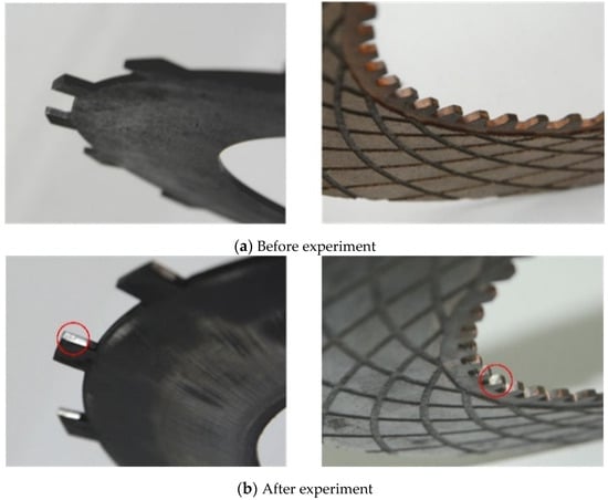
Figure 1.
Wear of the spline teeth.
This paper is devoted to investigating the effect of spline friction on the contact pressure and FT of friction components. The mathematical model regarding the spline friction of components is established first. Then, the numerical simulation and bench test are carried out by changing the number of friction pairs to verify the existence of spline friction. Finally, the effect of spline friction is summarized in detail, and the measures to improve the torque capacity and lifetime of multidisc clutch are proposed.
2. Numerical Model
Figure 2 presents a three-dimensional exploded layout of the wet clutch visually. The separate plates and friction discs are arranged alternately, and respectively mounted to the cylinder liner and driving shaft by splines []. The circlip installed in the groove of cylinder liner plays a role in limiting the axial position of friction components []. By pumping pressure oil into the piston chamber, the friction components start to rub against each other, and the axial gap between them gradually disappears [,]. Meanwhile, the separate plates, as the driven part, transfer the input power to the transmission system. Finally, the dynamic friction of spline teeth converts to static friction after the gap is eliminated [].
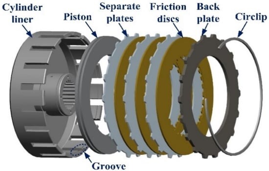
Figure 2.
Exploded layout of the multidisc clutch.
2.1. Spline Friction
Since the structural characteristics of the friction disc and separate plate are similar, the separate plate is chosen for the theoretical analysis and formula derivation. As shown in Figure 3, during the constant speed sliding process of the clutch, the separate plate reaches equilibrium status under the combined action of FT Tf and cylinder liner resistance torque Ts. The friction force, nominal tangential force and normal force acting on the spline teeth are expressed as Fs, Fcs and Fns, respectively. Moreover, Fp is the axial contact pressure applied on the separate plate. Hence, the equilibrium equation can be written as
where Rs is the pitch radius, Ns is the total number of splines in a single separate plate. It should be noted that the clockwise direction is positive, and the subscripts s and f represent separate plate and friction disc, respectively.
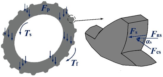
Figure 3.
Force diagram of the separate plate.
The normal force that cylinder liner acts on the involute spline can be given as
where αs is the pressure angle of spline teeth.
Therefore, the total friction force generated by spline teeth in a single separate plate can be expressed as
where μs is the coefficient of friction (COF) of spline teeth.
2.2. Contact Pressure
As shown in Figure 4, the pressure pc is evenly distributed on the piston. The friction components are numbered 0, 1, 2, …, i, I + 1, …, M, and the contact surfaces are similarly numbered S0, S1, S2, …, SM. For example, the two surfaces of component 1 are represented as S1, S2, respectively. Due to the spline friction, the contact pressure acting on the friction components is smaller compared with the oil pressure pc. To be more specific, the contact pressure gradually attenuates along the axial direction. Hence, the contact pressures on the two surfaces of friction component can be deduced as
where A is the contact area, namely, ; R2 and R1 are the outer and inner radii, respectively.
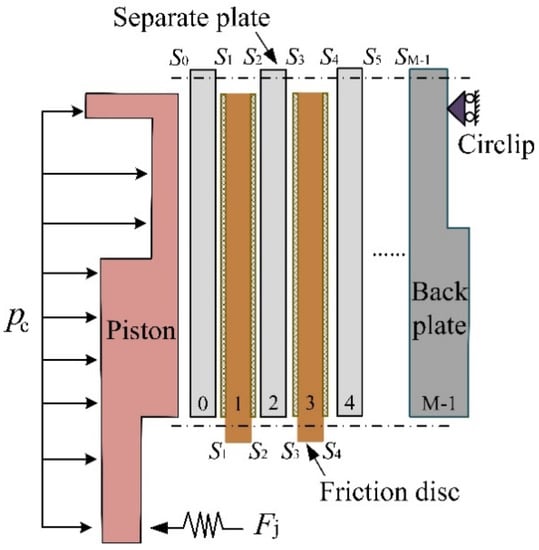
Figure 4.
Simplified 2D model of the multidisc clutch.
2.3. Friction Torque
As the friction material of the clutch is the copper-based powder metallurgy material, the interface COF can be expressed as []:
where ν, p and Θ are the relative sliding speed, average contact pressure and surface temperature, respectively.
Moreover, there is no relative motion between the piston, separate plate and back plate []. Hence, the FT on each friction component can be deduced as
Integrating Equations (3)–(6), the contact pressure on the two adjacent surfaces can be expressed as
where ξ is the attenuation coefficient of contact pressure. Thus, the attenuation coefficient ξs of the separate plate can be written as
Without consideration of the spline friction, the contact pressure is evenly distributed and there is no axial pressure attenuation. Consequently, the total FT transmitted by the clutch can be expressed as []:
When the spline friction exists, the total FT transmitted by the clutch can be given as
3. Numerical Simulation
The physical parameters of the friction components are listed in Table 1. With the consideration of spline friction, the simulation is conducted to investigate the effect of applied pressure and the number of pairs on the interface COF and the axial attenuation characteristics.

Table 1.
Physical parameters of the friction components.
According to Equation (5), the variation of interface COF under different applied pressure is shown in Figure 5. The interface COF gradually decreases as the applied pressure varies from 0.2 MPa to 2 MPa. This phenomenon can be interpreted as follows. The increasing applied pressure leads to the rise of the asperity contact area between friction pairs, which makes the friction pair become relatively smooth []. Therefore, the interface COF decreases gradually.
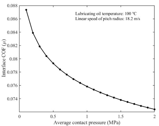
Figure 5.
Variation of the interface coefficient of friction (COF) regarding the contact pressure.
According to Equations (5), (7) and (8), the interface COF and contact pressure under different working conditions are shown in Figure 6 and Figure 7, respectively. As depicted in Figure 6, the farther the friction pair from the piston is, the greater the interface COF is. Moreover, as the applied pressure increases, the interface COF decreases gradually under the same number of friction pairs, which also has a good agreement with Figure 5.
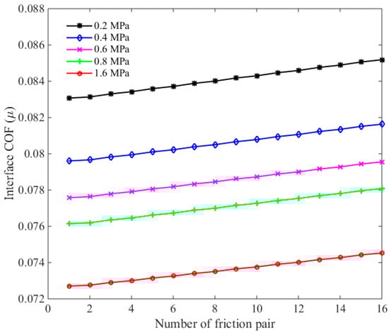
Figure 6.
Variation of the interface COF regarding the friction pairs.
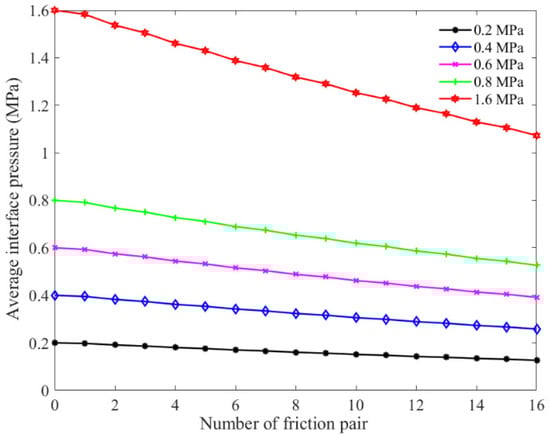
Figure 7.
Attenuation of the contact pressure.
Moreover, the contact pressure decreases gradually along the axial direction with an increase in the number of the friction pairs, as shown in Figure 7. Additionally, the attenuation amplitude of contact pressure increases gradually with the applied pressure growing. For instance, the contact pressure decreases from 0.2 MPa to 0.131 MPa as the number of friction pair varies from 0 to 16, a reduction of 0.069 MPa. When the applied pressure is 1.6 MPa, the contact pressure acting on p16 decreases to 1.106 MPa, an attenuation of 0.494 MPa, indicating a significant effect of spline friction to the attenuation of contact pressure.
As shown in Figure 8, the FT increases linearly with the increasing number of friction pairs in the ideal case, and the more the friction pair is, the greater the FT is. Considering the spline friction, the growth rate of FT decreases gradually as the number of friction pairs increases. The reason is that the growth of interface COF is much smaller than the attenuation amplitude of contact pressure. Moreover, the greater the applied pressure is, the greater the loss of FT is. In other words, the spline friction will weaken the torque transmission capacity of multidisc clutch. For example, the reduction amplitude of total FT in a 16-friction-pair system are 18.5 N·m and 114.58 N·m under the applied pressure of 0.2 MPa and 1.6 MPa, respectively. Therefore, when the friction pair reaches a certain number, it is not reliable to realize a substantial enhancement of FT by continuing to add the friction components.
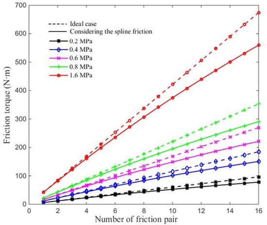
Figure 8.
Variation of the friction torque.
4. Attenuation Experiment
4.1. Experimental Equipment
As depicted in Figure 9, the test bench is mainly composed of the motor, the clutch pack, the hydraulic system and the data collection and control system. The pressure exerted on the piston is applied by the air pump. The lubricating oil flows into the clutch to lubricate and cool the friction components, and the heat exchanger is used to maintain the oil temperature at 100 °C. In addition, the data collection and control system plays a role in monitoring the real-time signals, including the rotating speed, the FT, the applied pressure and temperature, etc. Moreover, it can also calculate the equivalent COF μ* of friction pair according to the total FT T* measured by the torque sensor, the equivalent COF can be given as
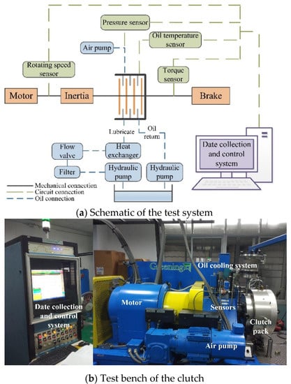
Figure 9.
Test system of the multidisc clutch.
The separate plate is made of the 65 Mn steel, while the friction discs are made of copper-based powder metallurgy material with nano-modifier, and the physical parameters are shown in Table 1. Moreover, the type of the lubricating oil is 10W/40-CF, while the average unit flow rate is 4 mL/(mincm2).
4.2. Experimental Method
Before the formal experiment, a running-in test is essential to ensure the equipment works properly to collect the valid data. The arrangement of clutch pack is divided into two categories, namely, the two-friction pair system and six-friction pair system. During the experiment of the former system, the initial motor speed is 2686 rpm. Moreover, an experiment cycle consists of five engagement tests at the applied pressure conditions of 0.2 MPa, 0.4 MPa, 0.6 MPa, 0.8 MPa, and 1.6 MPa, respectively. In order to reduce the measurement error, a total of 100 experiment cycles are carried out successively. Subsequently, the same experiment scheme is also conducted in the six-friction pair system. Figure 10 shows the experiment conditions.
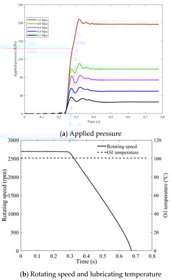
Figure 10.
Experiment conditions.
5. Results and Discussion
After experiments, the results of the equivalent COF and FT in the two-friction pair and six-friction pair system are shown in Figure 11 and Figure 12, respectively. The mean values of the equivalent COF, friction torques and single-pair friction torques in that two systems are shown in Table 2.
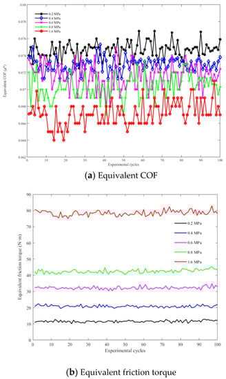
Figure 11.
Two-friction pair system.
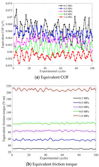
Figure 12.
Six-friction pair system.
Table 2.
Mean values of the two systems.
As the applied pressure increases, the equivalent COF gradually decreases, while the total FT increases nonlinearly. The equivalent COF in the two-friction pair system is greater than the other one under the same applied pressure. Moreover, the total FT in six-friction pair system does not reach three times as much as that in the two-friction pair system, indicating that the increase of friction pairs will enlarge the attenuation amplitude of axial contact pressure. In addition, the increasing applied pressure brings about the gradual decrease of the growth rate of average single-pair FT. The average single-pair FT is large than under various applied pressure conditions due to the spline friction. Therefore, the total FT cannot be significantly improved by increasing the applied pressure or using more friction pairs.
According to Figure 6 and Figure 7, the contact pressure and interface COF of the second friction pair is close to the first one, respectively. For example, when the applied pressure is 0.2 MPa, the ratios of the first two contact pressure and interface COF are 96.7% and 100.24%, severally. Therefore, the average equivalent COF in the two-friction pair system can be regarded as the interface COF of the first pair in the six-friction pair system. Besides, the range of spline COF μfs is 0.1–0.15 when the spline of friction component is in static friction status []. Accordingly, the total calculated torque in six-friction pair system and the relative error between the theoretical and experimental value can be obtained as shown in Table 3.
Table 3.
Total calculated torque and relative error.
Under the same applied pressure, the calculated torque decreases gradually with the increasing value of static COF. Besides, as the applied pressure increases, the total calculated torque increases approximately linearly. Moreover, the maximum relative error is within 10.3%, which not only verifies the reliability of theoretical model, but also testifies the significant effect of spline friction on the torque transmission capacity.
6. Conclusions
Considering the spline friction of friction components, the detailed numerical model and experimental method were established to study the FT attenuation in a wet multidisc clutch. Under various working conditions, the contact pressure and FT obtained by bench test show a good agreement with the numerical model, which also verifies the existence of spline friction. The conclusions can be summarized as follows: the spline friction is an important factor affecting the attenuation of the axial contact pressure and FT of the friction components. With the increase of applied pressure, the attenuation of the contact pressure along the axial direction increases gradually, whereas the growth rate of the average single-pair FT decreases. In addition, the average single-pair FT decreases gradually with the increasing friction pairs under the same applied pressure. To be more specific, it is not reliable to obtain a substantial enhancement of FT by continuing to add friction components when the friction pair reaches a certain number. Therefore, in order to reduce the effect of spline friction, it suggests to choose the reasonable structural parameters for friction component, to improve the manufacturing processes of spline and to increase the lubrication flow at the spline.
Author Contributions
M.C. is responsible for the theoretical modeling and research funding. B.Z. did the academic writing and the numerical analysis. Y.F. not only formulated the specific experimental scheme, but also provided the academic and experimental guidance. L.W. and H.W. did part of the experiments and organized the experimental data. All authors have read and agreed to the published version of the manuscript.
Funding
This work was supported by the National Natural Science Foundation of China (Grant NO. 51775045 and NO. 51975047), and the basic product innovation research project of the Ministry of Industry and Information Technology of China (JCCPCX201705).
Institutional Review Board Statement
Not applicable.
Informed Consent Statement
Not applicable.
Data Availability Statement
Not applicable.
Conflicts of Interest
The authors declare no conflict of interest.
References
- Yang, L.K.; Ma, B.; Ahmadian, M.; Li, H.Y.; Vick, B. Pressure distribution of a multidisc clutch suffering frictionally induced thermal load. Tribol. Trans. 2016, 59, 983–992. [Google Scholar] [CrossRef]
- Yu, L.; Ma, B.; Chen, M.; Li, H.Y.; Ma, C.N.; Liu, J.K. Comparison of the friction and wear characteristics between copper and paper based friction materials. Materials 2019, 12, 2988. [Google Scholar] [CrossRef] [PubMed]
- Tatara, R.A.; Payvar, P. Multiple engagement wet clutch heat transfer model. Numer. Heat Transfer A Appl. 2002, 42, 215–231. [Google Scholar] [CrossRef]
- Bao, H.Y.; Zhang, C.; Hou, X.N.; Lu, F.X. Wear Characteristics of Different Groove-Shaped Friction Pairs of a Friction Clutch. Appl. Sci. 2021, 11, 284. [Google Scholar] [CrossRef]
- Wang, S.Y.; Richard, J.H.; Yohan, N.; Anisha, S.; Lukas, L.; Liu, H.B.; Kaspar, A.; Joseph, H.; Davinder, S.; Kawal, R. Analysis of a Customized Clutch Joint Designed for the Safety Management of an Ultrasound Robot. Appl. Sci. 2019, 9, 1900. [Google Scholar] [CrossRef]
- Cui, J.Z.; Wang, C.T.; Xie, F.W.; Xuan, R.; Shen, G. Numerical investigation on transient thermal behavior of multidisk friction pairs in hydro-viscous drive. Appl. Therm. Eng. 2014, 67, 409–422. [Google Scholar] [CrossRef]
- Xie, F.W.; Cui, J.Z.; Sheng, G.; Wang, C.T.; Zhang, X.J. Thermal behavior of multidisk friction pairs in hydroviscous drive considering inertia item. J. Tribol. ASME 2014, 136, 041707. [Google Scholar] [CrossRef]
- Marklund, P.; Mäki, R.; Larsson, R.; Hoglund, E.; Khonsari, M.M. Thermal influence on torque transfer of wet clutches in limited slip differential applications. Tribol. Int. 2007, 40, 876–884. [Google Scholar] [CrossRef]
- Amedeo, T.; Emanuele, G.; Claudioet, A.; Renzo, C. Tribologic analysis, wear evolution and torque trend estimation of an LSD clutch pack. Int. J. Surf. Eng. Interdiscip. Mater. Sci. 2017, 5, 16–36. [Google Scholar]
- Finkin, E.F. The consequences of spline friction in multiple disk brake and clutch packs. J. Tribol. ASME 1968, 90, 65–71. [Google Scholar] [CrossRef]
- Newcomb, T.P.; Merritt, H.E. Effect of spline friction on the torque capacity and interface temperatures reached during a multi-disc clutch engagement. J. Mech. Eng. Sci. 2006, 4, 353–355. [Google Scholar] [CrossRef]
- Yu, L.; Ma, B.; Chen, M.; Li, H.Y.; Zhang, H.; Liu, J.K. Thermodynamic differences of different friction pairs in a multidisc clutch caused by spline friction: Numerical simulation and experimental verification. Tribol. Trans. 2019, 62, 724–736. [Google Scholar] [CrossRef]
- Yu, L.; Ma, B.; Chen, M.; Li, H.Y.; Liu, J.K.; Li, M.Y. Investigation on the failure mechanism and safety mechanical-thermal boundary of a multi-disc clutch. Eng. Fail. Anal. 2019, 103, 319–334. [Google Scholar] [CrossRef]
- Li, M.; Khonsari, M.M.; McCarthy, D.M.C.; Lundin, J. Parametric analysis of wear factors of a wet clutch friction material with different groove patterns. Proc. Inst. Mech. Eng. Part J 2017, 231, 1056–1067. [Google Scholar] [CrossRef]
- Ma, B.; Yang, L.K.; Li, H.Y.; Lan, N. Hot judder behavior in multidisc clutches. Proc. Inst. Mech. Eng. Part J 2017, 231, 136–146. [Google Scholar] [CrossRef]
- Zhang, H.; Zhao, X.X.; Yang, J.; Zhang, W.M. Optimizing Automatic Transmission Double-Transition Shift Process Based on Multi-Objective Genetic Algorithm. Appl. Sci. 2020, 10, 7794. [Google Scholar] [CrossRef]
- Cho, J.; Lee, Y.; Kim, W.; Jang, S. Wet single clutch engagement behaviors in the dual-clutch transmission system. Int. J. Auto. Tech. Kor. 2018, 19, 463–472. [Google Scholar] [CrossRef]
- Zhao, E.H.; Ma, B.; Li, H.Y. The tribological characteristics of Cu-based friction pairs in a wet multidisk clutch under nonuniform contact. J. Tribol. Trans. ASME 2018, 140, 011401. [Google Scholar] [CrossRef]
- Lingesten, N.; Marklund, P.; Höglund, E. The influence of repeated high-energy engagements on the permeability of a paper-based wet clutch friction material. Proc. Inst. Mech. Eng. Part J J. Eng. Tribol. 2017, 231, 1574–1582. [Google Scholar] [CrossRef]
- Lin, X.H.; Xi, J.Q.; Hao, S.Q. The calculation model of the friction torque on a dry clutch. Proc. Inst. Mech. Eng. Part D J. Automob. Eng. 2017, 231, 1796–1805. [Google Scholar] [CrossRef]
- Li, W.B.; Huang, J.F.; Fei, J.; Cao, L.Y.; Yao, C.Y. Simulation and application of temperature field of carbon fabric wet clutch during engagement based on finite element analysis. Int. Commun. Heat Mass. 2016, 71, 180–187. [Google Scholar]
Publisher’s Note: MDPI stays neutral with regard to jurisdictional claims in published maps and institutional affiliations. |
© 2021 by the authors. Licensee MDPI, Basel, Switzerland. This article is an open access article distributed under the terms and conditions of the Creative Commons Attribution (CC BY) license (http://creativecommons.org/licenses/by/4.0/).