1. Introduction
With the rapid development of space optical payload technology, the design of optical payload has shifted from focusing solely on basic indicators such as resolution and field of view (FOV) to a systematic indicator of multi-purpose and high-efficiency applications. Among them, the multifunctional and multispectral imaging capability of single payload based on highly integrated detectors is an important developmental direction to enhance the observation capability of payloads. Judging from the current development of payloads in the world, many satellite payloads adopt the idea of multi-spectral integrated design. For example, the United States commercial satellite Worldview-3 has 1 Panchromatic band, 8 Multispectral bands, 8 Multiband in SWIR (Shortwave Infrared) and 12 CAVIS (Corrects for Clouds, Aerosols, Vapors, Ice, & Snow) bands [
1]. In addition to obtaining high-resolution optical images, Worldview-3 can also obtain short-wave infrared band images, which has a good application prospect in fire detection and mineral detection [
2]. For another example, South Korea’s KompSat-3A satellite not only has 1 Panchromatic band and 4 Multispectral bands, but also has a 3.3–5.2 um mid-wave infrared imaging capability [
3,
4]. The Goodrich SYERS-2 detector used by the ORS-1 satellite, launched by the United States in 2011, has seven imaging spectrum bands, including panchromatic band, near-infrared band, two short-wave infrared bands, one mid-wave infrared band and red band and green band [
5]. The GaoFen-4 (GF-4) satellite launched by China in 2015 can achieve a resolution of 50m in the visible and near-infrared bands of 400–900 nm and a resolution of 400m in the mid-wave infrared band of 3.5um to 4.1um in an orbit of about 36,000 km [
6].
The advantage of infrared imaging is that it mainly relies on the radiation imaging of the target and the background, and generally does not require external environmental light sources. The infrared imaging system is less affected by severe weather such as rain, snow, wind and frost, and can also image normally at night [
7]. It has the ability to work all day, and has a certain ability to recognize camouflaged and anti-interference targets. However, the infrared detector is not sensitive to the brightness changes of the scene, and the imaging resolution and clarity are relatively low, which is not conducive to human eye judgment [
8]. The visible light band remote sensing camera can obtain high-resolution images, the images are clear, in line with human visual habits, and can show the true color characteristics of the target. However, the visible light band camera is greatly affected by weather conditions, and its observation ability is limited in rain, snow, and cloudy environments, and its night observation ability is relatively weak [
9]. The low-light detector can effectively enhance the camera’s ability to acquire information in the visible light band in low-illumination environments, extend the effective working time of the camera, and to a certain extent make up for the camera’s weak night observation ability [
10].
The single-spectrum detector imaging system can acquire very limited spectral information in the target area, while the use of multi-detector integrated cameras working in different spectral bands can make use of the data complementarity and redundancy of different detectors. This results in a single payload owning the ability to simultaneously acquire high-resolution images of multiple spectral bands in the target area, which greatly enhances the camera’s ability to adapt to the environment and the ability to acquire information about the target.
According to the current demand for multi-band imaging equipment, this paper proposes a compact visible/long-wave infrared dual-band common aperture design. By sharing the primary and secondary mirrors and the separate field of view design, the two bands can be imaged on one device at the same time. The design in this article makes full use of the space on the back of the primary mirror to make the structure more compact. The second section of this paper introduces the integrated design scheme and the calculation method of the initial structure in detail; the third section uses the Code V software to design the two subsystems separately and combines the two systems;
Section 4 carries out the system Tolerance analysis;
Section 5 analyzes the ambient temperature of the system;
Section 6 analyzes the optical transmittance of the system; and finally summarizes the main conclusions.
2. Integrated Design Principles and Schemes
Most space telescope designs use reflective or catadioptric optical systems. The reflective system can fold the optical path, it has a compact structure and is suitable for a long focal length optical system. In addition, the reflective system does not have the problem of chromatic aberration and secondary spectrum. The reflective system has relatively small restrictions on the aperture size, is more suitable for lightweight, and has a greater advantage in temperature control [
11].
Reflective systems include two types: coaxial reflective system and off-axis reflective system. Off-axis reflective systems can be designed with a larger field of view (greater than 2°), but relatively, their size and weight will also become larger. It is not conducive to the compression of the volume; in addition, the processing, testing and overall assembly and adjustment of off-axis reflective mirrors are more difficult and more costly. Although the field of view of the coaxial reflective system cannot be designed to be large, its overall size is relatively small, the stability of the opto-mechanical system is good, and the processing and installation are more convenient [
12].
The choice of the optical system structure should be as far as possible to choose a structure that is conducive to design, manufacturing and assembly on the premise of meeting the design indicators. Additionally, it is necessary to fully consider the cost factors of the camera in processing, testing, assembly and launching, etc., and reduce the volume and weight of the payload as much as possible.
2.1. Integrated Design Scheme
This paper proposes a visible light and infrared dual-band integrated system design. The system structure is shown in
Figure 1. The visible light band and the infrared band share the primary and secondary mirror of the camera. The integrated system separates the two wavebands by adopting a separate field of view design. The infrared band field of view partially overlaps the visible light band field of view, and field of view of the two band tilt directions are opposite, and the tilt angles are the same.
The integrated design scheme in this paper is mainly motivated by the following considerations.
(1). The integrated design of this paper is further optimized on the basis of the coaxial reflective system. This paper intends to design an integrated system with small volume and compact structure, which does not require a high field of view. With the same aperture, the coaxial reflective system is more advantageous in volume than the off-axis reflective system, so this paper chooses the coaxial reflective integrated scheme.
(2). The separate field of view design can make the visible light band and the infrared band separate naturally at the central hole of the primary mirror, without the use of band separation device, which simplifies the system structure to a certain extent. The visible light band focal plane can be arranged in a mixture of panchromatic and low-light detectors, and the detectors can be switched freely under different lighting conditions, so that the visible light band subsystem can accomplish observation tasks during the day and night.
(3). The rear optical system of the two subsystems makes full use of the back area of the primary mirror, which improves the space utilization of the camera to a certain extent and makes the system structure more compact. The primary and secondary mirrors of the system can also be further compressed by the expandable structure design to further improve the space utilization.
2.2. Initial Structure of the Integrated System
In order to make the visible light band and infrared band light path separated at the central opening of the primary mirror, and so that the light does not interfere with the components of the camera, the initial structure of the camera should be a coaxial three-mirror system with an intermediate image plane. The initial structure has seven free variables, where
e12,
e22, and
e32 represent the quadric characteristics of the three mirrors,
β1 is the magnification of the secondary mirror,
β2 is the magnification of the third mirror, and
α1 is the obstruction ratio of the secondary mirror to the primary mirror,
α2 is the obstruction ratio of the third mirror to the secondary mirror. Since there is an intermediate image plane between the primary and secondary mirrors,
α2 < 0,
β2 < 0; the beam emitted by the secondary mirror is a convergent beam, so
β1 < 0;
α1 represents the distance between the primary and secondary mirrors, generally 0 <
α1 < 1. In addition, it is also necessary to control the distance Δ between the intermediate image plane and the center of the primary mirror to better control the interference problem between the two subsystems. Δ can be calculated by Equation (1), where
l2 is the distance from the secondary mirror to the focal point of the primary mirror, and
f1′ is the focal length of the primary mirror [
13]. The initial structure diagram of the three-mirror system is shown in
Figure 2.
Through
α1,
α2,
β1, and
β2, the apex radius of curvature
R1,
R2,
R3 of the primary mirror, secondary mirror and the third mirror, the distance
d1 from the primary mirror to the secondary mirror, the distance
d2 from the secondary mirror to the third mirror, and the distance
l3’ between the third mirror to the image plane can be determined. The calculation equation refers to Equations (2)–(4).
According to the aberration elimination condition, Equations (5)–(8), the quadric coefficients of the three mirrors can be calculated. The three-mirror optical system can simultaneously eliminate four kinds of aberrations: spherical aberration, coma, astigmatism, and field curvature.
The initial structure of the system can be determined by the Equations (5)–(8), and the system can be further optimized by optical design software.
3. System Design Results
The integrated system in this paper is based on a 500 km orbit. The system has two imaging bands, the visible light band is 450–900 nm, covering visible light and near-infrared bands; the long-wave infrared band is 7700–10,500 nm. The pupil diameter of the system is 500 mm, and the system requires that the ground resolution in the visible light band is better than 1 m, the ground resolution in the long-wave infrared band is better than 10 m, and the ground width is greater than 8 km. According to the above system indicators, the design parameters of the two subsystems can be calculated separately, and the actual design of the two subsystems can be carried out.
3.1. Visible Light Band Subsystem Design
A detector with a pixel size of 10 μm is selected for the visible light band. According to calculations, the focal length of the system is 5000 mm, and the field of view is 1° × 0.2°. The system design parameters are shown in
Table 1.
The schematic diagram of the visible light band subsystem is shown in
Figure 3. The system adopts a coaxial biased field design, consisting of three quadric mirrors and a folding mirror. The surfaces of the primary mirror and the third mirror are ellipsoid, the surface of the secondary mirror is hyperboloid, and the aperture diaphragm is located on the primary mirror. The angle between the incident light in the central field of view and the horizontal direction is 0.9°, and the Alpha tilt of the folding mirror is 6°. The intermediate image plane is located behind the main mirror, which is a non-ideal image. Placing a stray light stop at the intermediate image position can reduce the influence of stray light on the system. The folding mirror is located near the middle image plane, the size is small, and its direction has little effect on the image quality.
We select nine points on the image plane A (−0.5°, 1.1°), B (−0.5°, 1°), C (−0.5°, 0.9°, D (0°, 1.1°), E (0°, 1°), F (0°, 0.9°), G (0.5°,1.1°), H (0.5°, 1°), I (0.5°, 0.9°) as the field of view points for evaluating the panchromatic imaging performance of the system. The image quality evaluation of the system is shown in
Figure 4. It can be seen from the figure that the MTF curve of the system is close to the diffraction limit, and the average MTF value at 50 lp/mm is higher than 0.45; from the image point diagram of the system, it can be seen that the image points are all smaller than Airy disk; from the field curvature and distortion curve, it can be seen that the distortion is less than 0.5%. The image quality is good and meets the expected requirements.
3.2. Infrared Subsystem Design
The infrared band subsystem uses a detector with a pixel size of 25 μm, the focal length of the system is 1250 mm, and the field of view is the same as the visible light band, 1° × 0.2°. The system design parameters are shown in
Table 2.
The infrared band subsystem is composed of five mirrors, the primary and secondary mirrors are shared with the visible light band, the third mirror and the fifth mirror are ellipsoidal, and the fourth mirror is hyperboloid. The angle between the incident light in the central field of view and the horizontal direction is also 0.9°, and the direction is opposite to the visible light band. The infrared system structure diagram is shown as in
Figure 5.
We select nine points A (−0.5°, −1.1°), B (−0.5°, −1°), C (−0.5°, −0.9°), D (0°, −1.1°), E (0°, −1 °), F (0°, −0.9°), G (0.5°, −1.1°), H (0.5°, −1°), I (0.5°, −0.9°) on the image plane to evaluate the long-wave infrared imaging performance of the system [
14]. The image quality evaluation of the system is shown in
Figure 6. It can be seen from the figure that the MTF curve of each field of view of the system in the infrared band is close to the diffraction limit, and the average MTF value at 20 lp/mm reaches 0.36. It can be seen from the image point diagram that the energy of the image points is concentrated, and the image points in each field of view are much smaller than the Airy disk. In addition, due to the asymmetrical field of view of the off-axis system, the distortion curve in the Code V software cannot truly reflect the system distortion. We can see from the text data of the distortion grid that the maximum value of the system Rad Dist in Code V is 0.4%, and the maximum value of Tan Dist is 0.12%. The image quality of the system is good and meets the expected requirements.
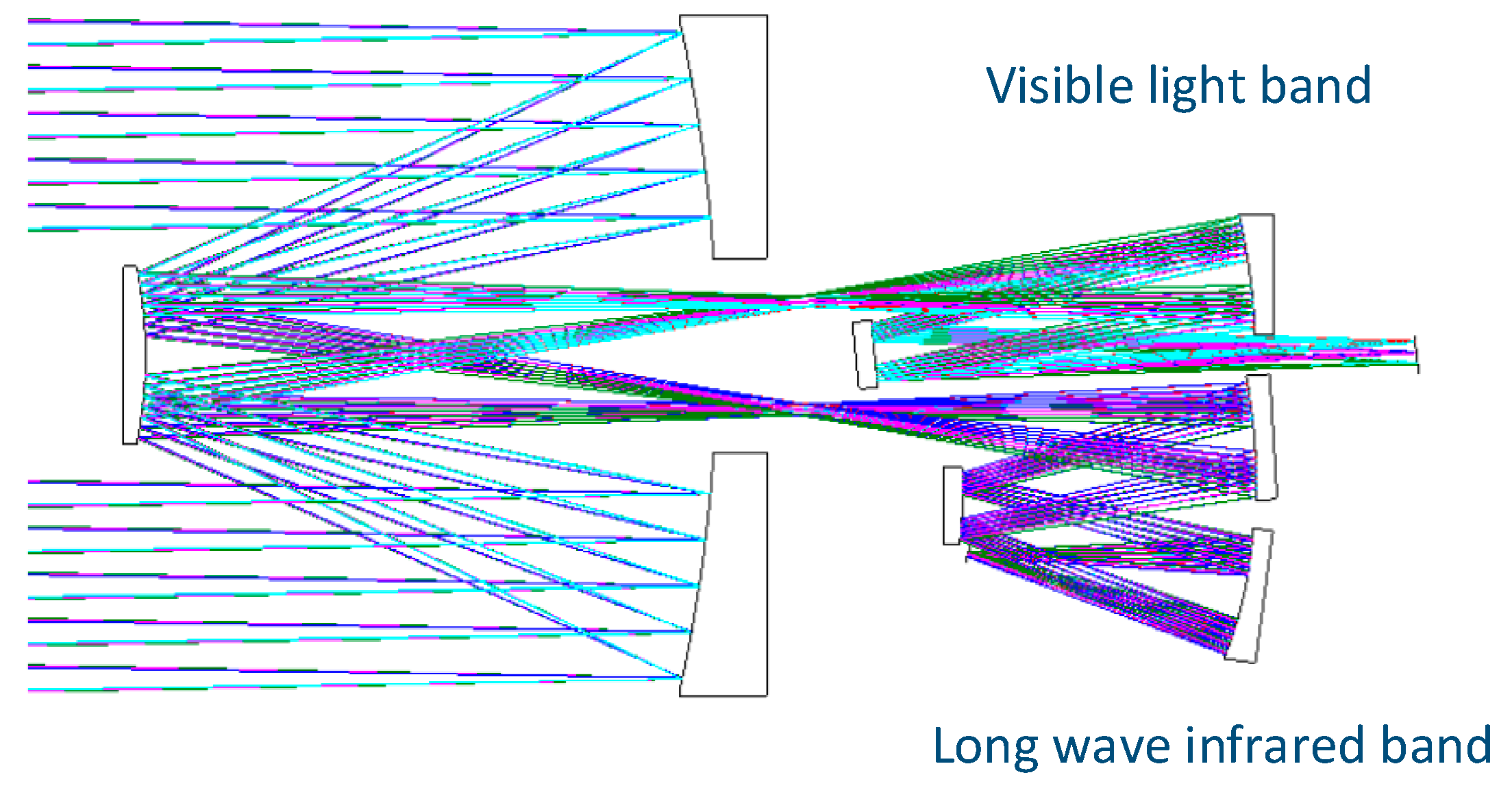
3.3. Integrated System Design Results
The visible light subsystem and the long-wave infrared subsystem are combined, and the final integrated design result is shown in
Figure 7, and the three-dimensional diagram is shown in
Figure 8. The horizontal length of the entire system is about 900 mm, and the longitudinal length is about 500 mm. It can be seen from the figure that the overall layout of the integrated system is reasonable, the structure is compact, and the design scheme is reasonable and feasible.
4. System Tolerance Analysis
We assigned tolerances to the two sub-systems of the integrated system, and performed Monte Carlo analysis on each sub-system based on the tolerances. The integrated system is a reflective system, mainly based on tolerances such as radius tolerance, mirror displacement, mirror tilt and other tolerances [
15]. The results of the tolerance distribution of the visible light subsystem are shown in
Table 3. The analysis shows that the displacement tolerance of the secondary mirror of the system is more sensitive. Through the 500-run Monte Carlo analysis, the MTF value of the system with tolerance is 0.386.
The primary and secondary mirrors of the long-wave infrared subsystem are shared with the visible light band, so the result of the tolerance distribution of the primary and secondary mirrors remains unchanged. The rear optical system tolerance distribution results in the infrared band are shown in
Table 4. The infrared band has a longer wavelength, so the tolerance requirements are relatively loose. Through 500-run Monte Carlo analysis, the MTF value of the system with tolerance is 0.345. It can be seen from the results that the infrared system is less sensitive to various tolerances, and the MTF of the system with tolerances only drops by 0.015, so various tolerance values can be appropriately increased.
5. System Environment Temperature Analysis
We use Code V software to simulate the effect of temperature on the image quality of the two subsystems in a vacuum environment. The camera uses silicon carbide (SiC) as the mirror substrate, the primary and secondary mirror structures are made of carbon fiber, and the rear optical system structure is made of titanium alloy.
The result of the system MTF varying with the ambient temperature is shown in
Figure 9. It can be seen from the figure that the system MTF value of the visible light band subsystem is higher than 0.4 at 50 lp/mm between 18 ℃ and 22 ℃, and reaches the highest point of 0.45 at 20 ℃. The system MTF value of the long-wave infrared band subsystem is higher than 0.354 at 20 lp/mm between −20 ℃ and −60 ℃, and reaches the highest point of 0.364 at 20 ℃. The two subsystems have certain adaptability to environmental temperature changes, and the simulation results achieve the expected results [
16,
17].
6. System Optical Transmittance Analysis
The optical energy loss of the optical system is determined by factors such as the number of reflective surfaces in the optical path, the reflectivity of the reflective surface, the number of lenses, the transmittance of the lenses, and the size of the central opening of the reflective surface. The camera’s visible light and long-wave infrared share the primary and secondary mirrors. The working spectrum ranges from 450 nm to 10,500 nm, and the spectral range is large. It is difficult to achieve high optical efficiency of the mirror in the full spectrum through conventional coating methods.
Under normal circumstances, the wide-spectrum reflective coating of a large-aperture mirror is a metal-protected or metal-enhanced film structure. Commonly used metal materials for reflective films include aluminum, silver, and gold. Among them, gold has high reflectivity only in the wavelength band greater than 550 nm, which cannot meet the requirements of the camera’s operating spectrum. Aluminum and silver have their own advantages and disadvantages. Aluminum has a high reflectivity in the ultraviolet band, but there is a low reflectivity near 800 nm, which has a greater impact on the reflectivity in the visible and near-infrared region, and its average reflectivity in each spectrum is low. Silver has good consistency and high reflectivity in a wide range of wavelengths greater than 350 nm [
18].
According to the existing optical film system theory and coating process technical conditions, the film system design of the primary and secondary mirrors in the camera in this paper is carried out by using silver as the main film layer. The average reflectivity of the reflective film on the surface of the primary and secondary mirrors in the visible spectrum is about 0.97, and the average reflectivity in the long-wave infrared spectrum is about 0.985. The reflectivity of other mirrors in the optical system is 0.97. The central opening radius of the primary mirror is 75 mm, and the radius of the primary mirror is 250 mm, so the actual light transmission rate of the main mirror is 91%. After calculation, the transmittance of the visible light band system is 0.806, and that of the long-wave infrared band system is 0.806.
7. Conclusions
Multi-band integrated design is currently one of the important means for space remote sensing cameras to expand the observation spectrum, improve observation capabilities and environmental adaptability. Based on the coaxial reflection system, this paper designs a compact visible light and long-wave infrared dual-band integrated space remote sensing camera. The camera can simultaneously obtain information in the visible and near-infrared bands of 450–900 nm and the long-wave infrared bands of 7700–10,500 nm. The two bands share the primary and secondary mirrors of the system, and the band separation is achieved through a separate field of view design. This design can make full use of the space on the back of the main lens, which greatly reduces the size of the camera. In this paper, the two-band subsystems are designed and simulated separately, and the imaging quality is good, and the MTF value of the system is close to the diffraction limit. In addition, this article further analyzes the error produced in the process of camera processing and adjustment, as well as the impact of environmental temperature changes on the image quality of the system. Finally, this article analyzes the reflective surface film of the system, and calculates the optical transmittance of each subsystem. After analysis, the integrated design of this article has good image quality and meets the expected requirements.
Author Contributions
Conceptualization, X.F. and R.L.; methodology, G.Z. and R.L.; software, G.Z. and R.L.; validation, X.F., L.F. and R.L.; formal analysis, G.Z. and R.L.; investigation, R.L.; resources, X.F.; data curation, R.L.; writing—original draft preparation, R.L.; writing—review and editing, X.F. and L.F.; visualization, R.L.; supervision, X.F. and G.Z.; project administration, X.F.; funding acquisition, X.F. All authors have read and agreed to the published version of the manuscript.
Funding
This research received no external funding.
Institutional Review Board Statement
Not applicable.
Informed Consent Statement
Not applicable.
Conflicts of Interest
The authors declare no conflict of interest.
References
- Longbotham, N.; Pacifici, F.; Malitz, S.; Baugh, W.; Camps-Valls, G. Measuring the spatial and spectral performance of WorldView-3. In Proceedings of the Hyperspectral Imaging and Sounding of the Environment, Lake Arrowhead, CA, USA, 1–4 March 2015; p. HW3B. 2. [Google Scholar]
- Xian, G.; Shi, H.; Dewitz, J.; Wu, Z. Performances of WorldView 3, Sentinel 2, and Landsat 8 data in mapping impervious surface. Remote Sens. Appl. Soc. Environ. 2019, 15, 100246. [Google Scholar] [CrossRef]
- Erdenebaatar, N.; Kim, J.; Kim, T. Analysis of geometric and spatial image quality of KOMPSAT-3A imagery in comparison with KOMPSAT-3 imagery. Korean J. Remote Sens. 2017, 33, 1–13. [Google Scholar] [CrossRef] [Green Version]
- Jeon, M.-J.; Lee, S.-R.; Kim, E.; Lim, S.-B.; Choi, S.-W. Launch and early operation results of KOMPSAT-3A. In Proceedings of the 14th International Conference on Space Operations, Daejeon, Korea, 16–20 May 2016; p. 2394. [Google Scholar]
- Andy, C. Goodrich Supplies ORS-1 Satellite with SYERS-2 Multi-Spectral Sensor. 2011. Available online: http://www.azosensors.com/News.aspx?newsID=2588 (accessed on 30 April 2011).
- Wang, M.; Cheng, Y.; Long, X.; Yang, B. On-Orbit Geometric Calibration Approach for High-Resolution Geostationary Optical Satellite GaoFen-4. Int. Arch. Photogramm. Remote Sens. Spatial Inf. Sci. 2016, 41, 389–394. [Google Scholar] [CrossRef] [Green Version]
- Guo, Y.; Yu, X.; Cai, K. Optical design of TV/IR dual-band common-aperture system. Infrared Tech. 2018, 40, 125–132. [Google Scholar]
- Wang, Y.; Li, W.; Meng, Q. Design of a visible light/LWIR dual-band mutual path optical system. Electron. Opt. Contr. 2018, 25, 94–97. [Google Scholar]
- Li, R.; Zou, G.; Wang, C.; Fan, X. Optical design of visible and infrared integrative camera. Acta Opt. Sin. 2016, 36, 217–224. [Google Scholar]
- Zou, M.; Zhang, J.; Zhong, S.; Li, Z.; Yao, L. Low-light-level CMOS imaging sensor with CTIA and digital correlated double sampling. Analog Integr. Circuits Signal Process. 2019, 101, 449–461. [Google Scholar] [CrossRef]
- Li, X.; Wu, M. Design of Compact Space Optical System with Large Relative Aperture and Large Field of View Based on Mangin Mirror. In Proceedings of the 6th International Symposium of Space Optical Instruments and Applications, Delft, the Netherlands, 24–25 September 2019; pp. 253–265. [Google Scholar]
- Xu, C.; Cheng, D.; Chen, J.; Wang, Y. Design of all-reflective dual-channel foveated imaging systems based on freeform optics. Appl. Opt. 2016, 55, 2353–2362. [Google Scholar] [CrossRef] [PubMed]
- Padin, S. Three-mirror anastigmat for cosmic microwave background observations. Appl. Opt. 2018, 57, 2314–2326. [Google Scholar] [CrossRef] [PubMed]
- Wang, C.; Zou, G.; Pang, Z.; Li, R.; Fan, X. Design of large field for visible/infrared integrated optical system. Infrared Laser. Eng. 2016, 45, 164–169. [Google Scholar]
- Fan, X.; Zou, G.; Qiu, Y.; Pang, Z.; Zhao, H.; Chen, Q.; Pan, Y.; Yuan, H. Optical design of the visible telescope for the SVOM mission. Appl. Opt. 2020, 59, 3049–3057. [Google Scholar] [CrossRef] [PubMed]
- Li, S.; Wang, Y.; Zhang, H.; Yu, F. Thermal Analysis and Validation of GF-4 Remote Sensing Camera. Int. J. Therm. Sci. 2020, 29, 992–1000. [Google Scholar] [CrossRef]
- Kovács, R.; Józsa, V. Thermal analysis of the SMOG-1 PocketQube satellite. Appl. Therm. Eng. 2018, 139, 506–513. [Google Scholar] [CrossRef]
- Zhao, H. An approach to 8–14um IR reflection film. J. Appl. Opt. 1993, 14, 43–45. [Google Scholar]
| Publisher’s Note: MDPI stays neutral with regard to jurisdictional claims in published maps and institutional affiliations. |
© 2021 by the authors. Licensee MDPI, Basel, Switzerland. This article is an open access article distributed under the terms and conditions of the Creative Commons Attribution (CC BY) license (https://creativecommons.org/licenses/by/4.0/).


