
Study of the Error Caused by Camera Movement for the Stereo-Vision System

Abstract
:1. Introduction
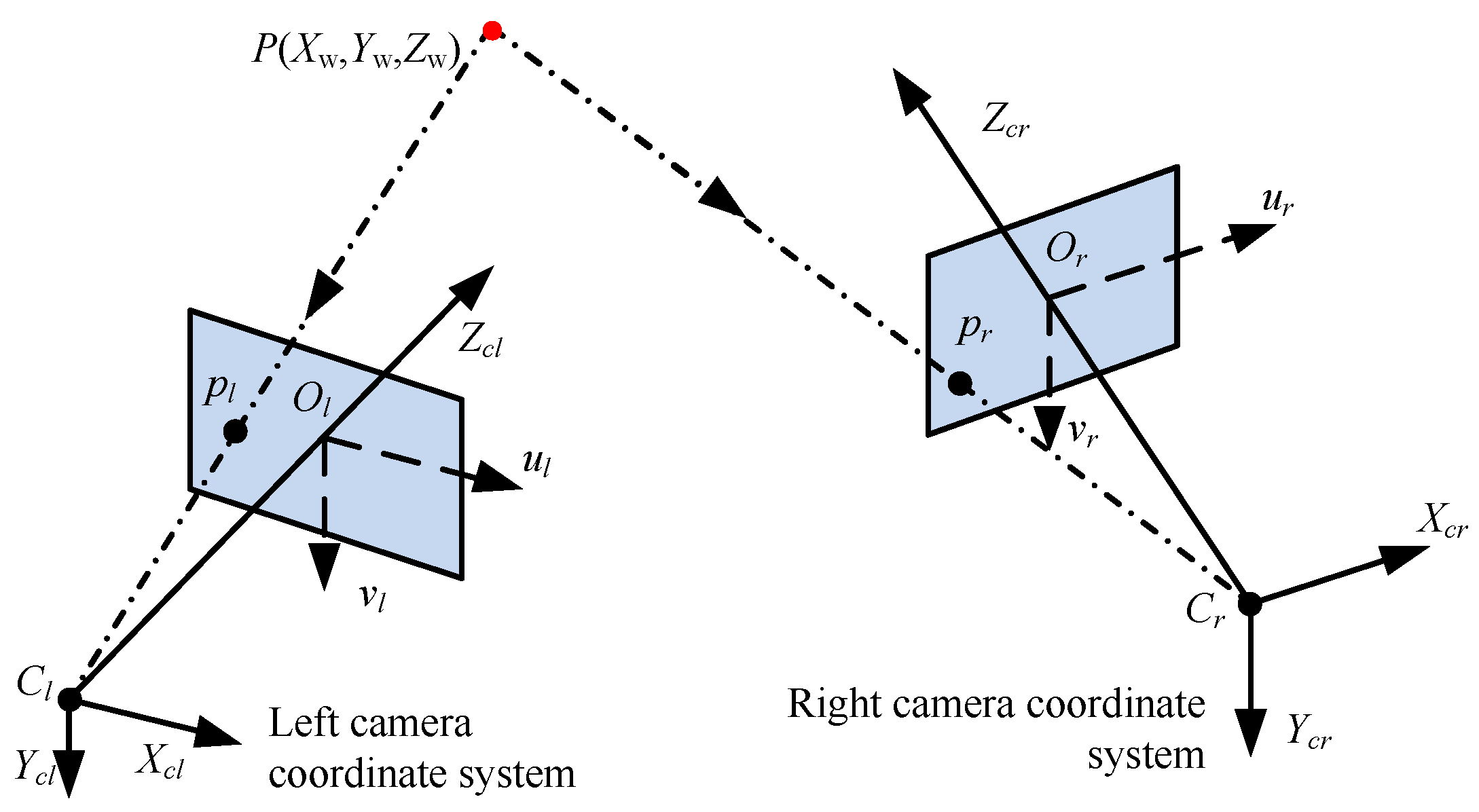
2. Principle
3. Camera Movement Errors
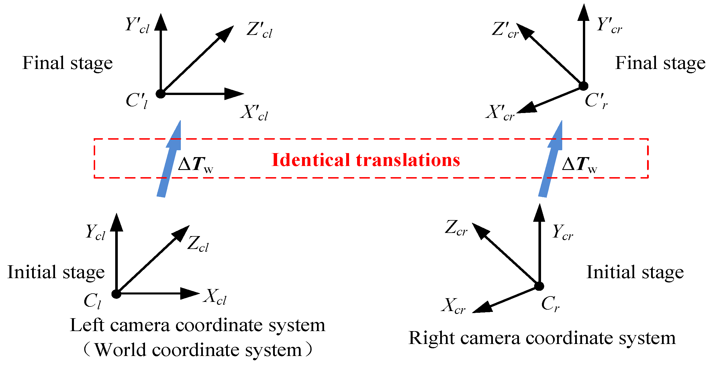
- (1)
- Identical translations of the left and right cameras when the positions and orientations of their optical centers have the same changes.
- (2)
- Identical rotations of the two cameras when the orientations of two cameras have the same changes.
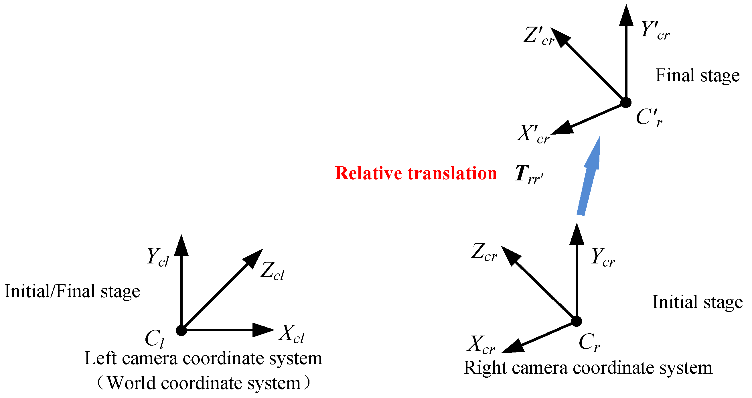
- (3)
- Relative translation when the position of the left camera relative to that of the right camera is changed.
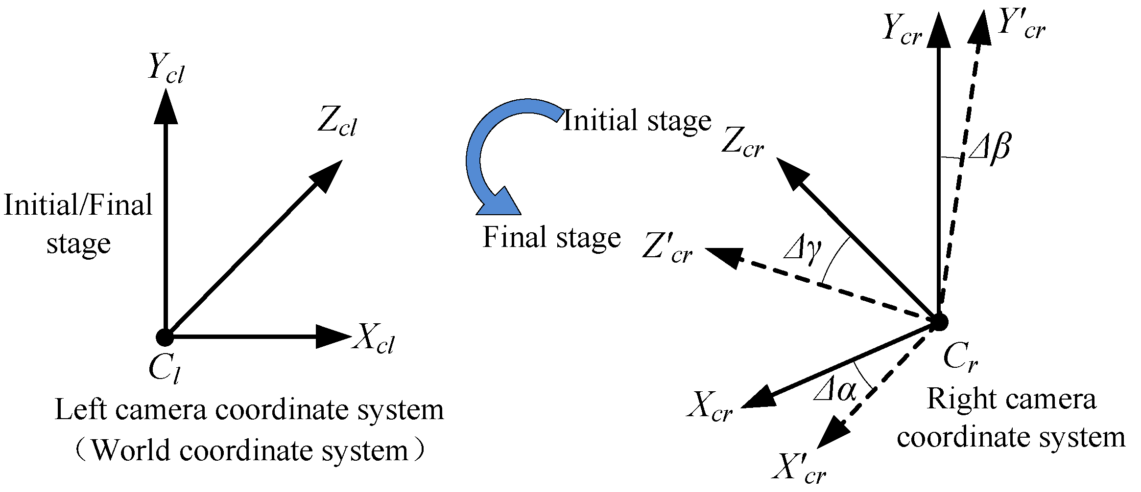
- (4)
- Relative rotation when the orientation of the left camera relative to that of the right camera is changed.
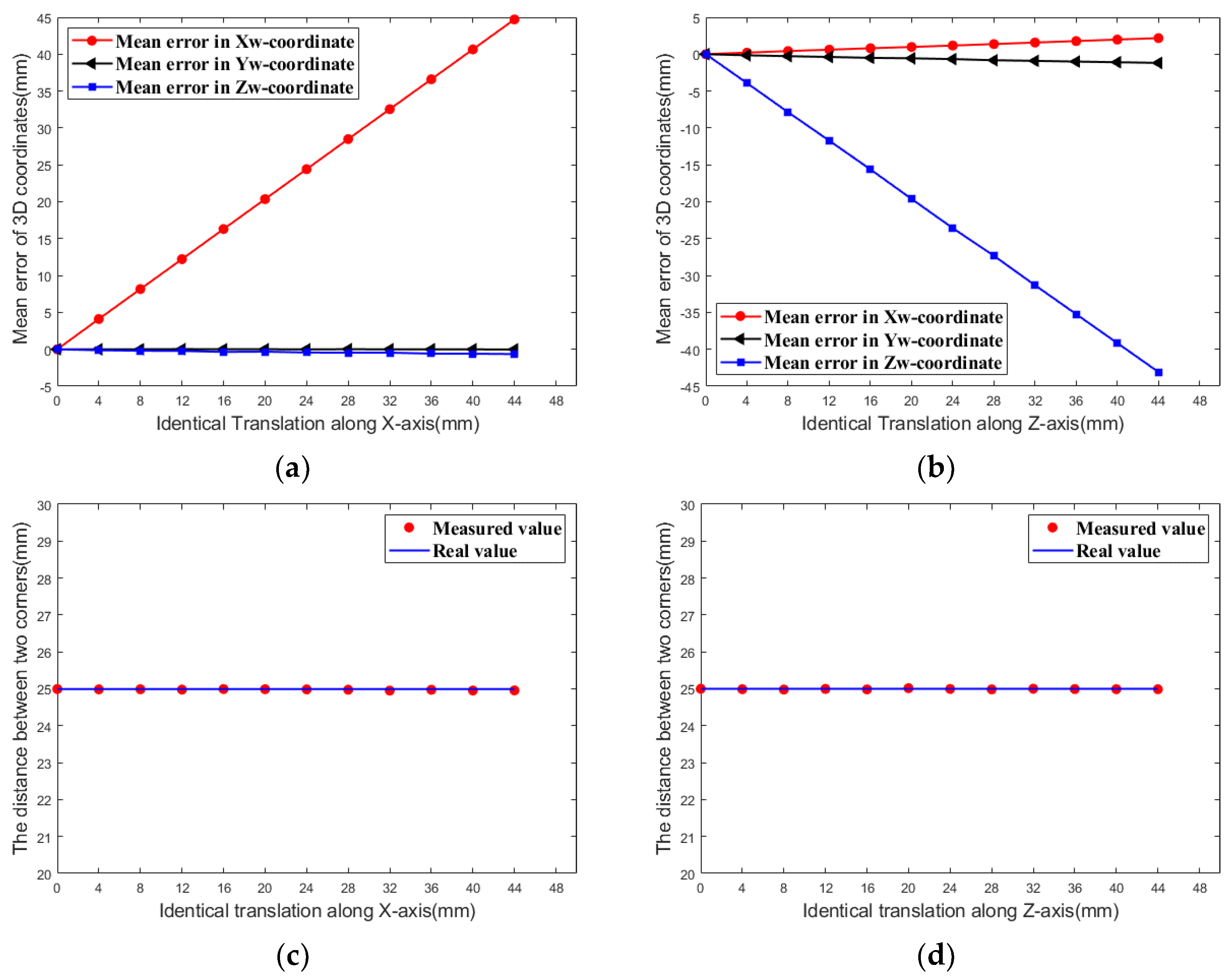
3.1. Identical Translations
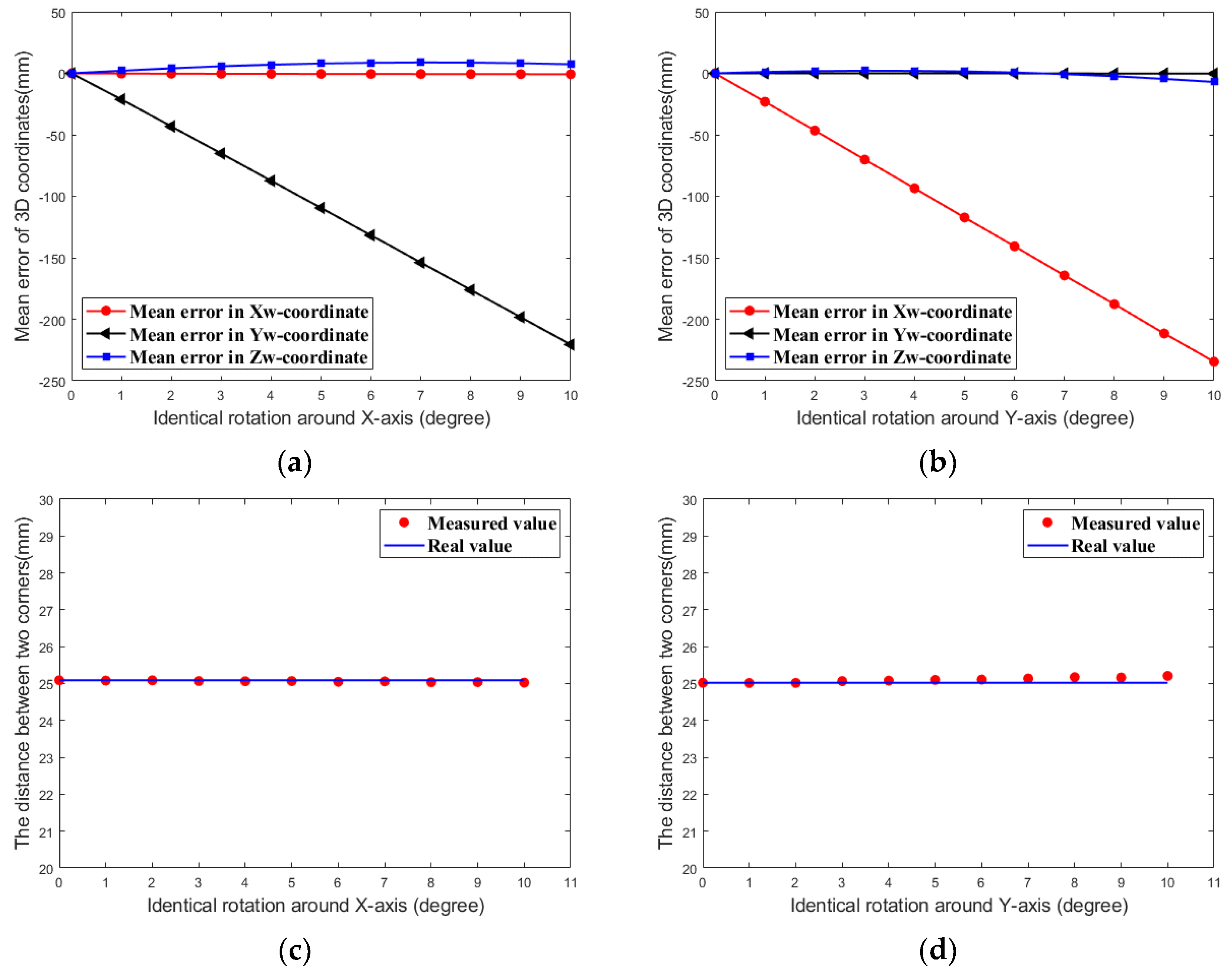
3.2. Identical Rotations
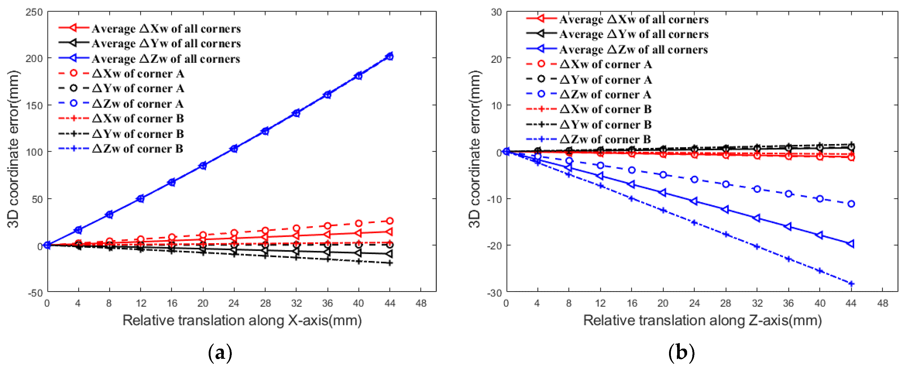
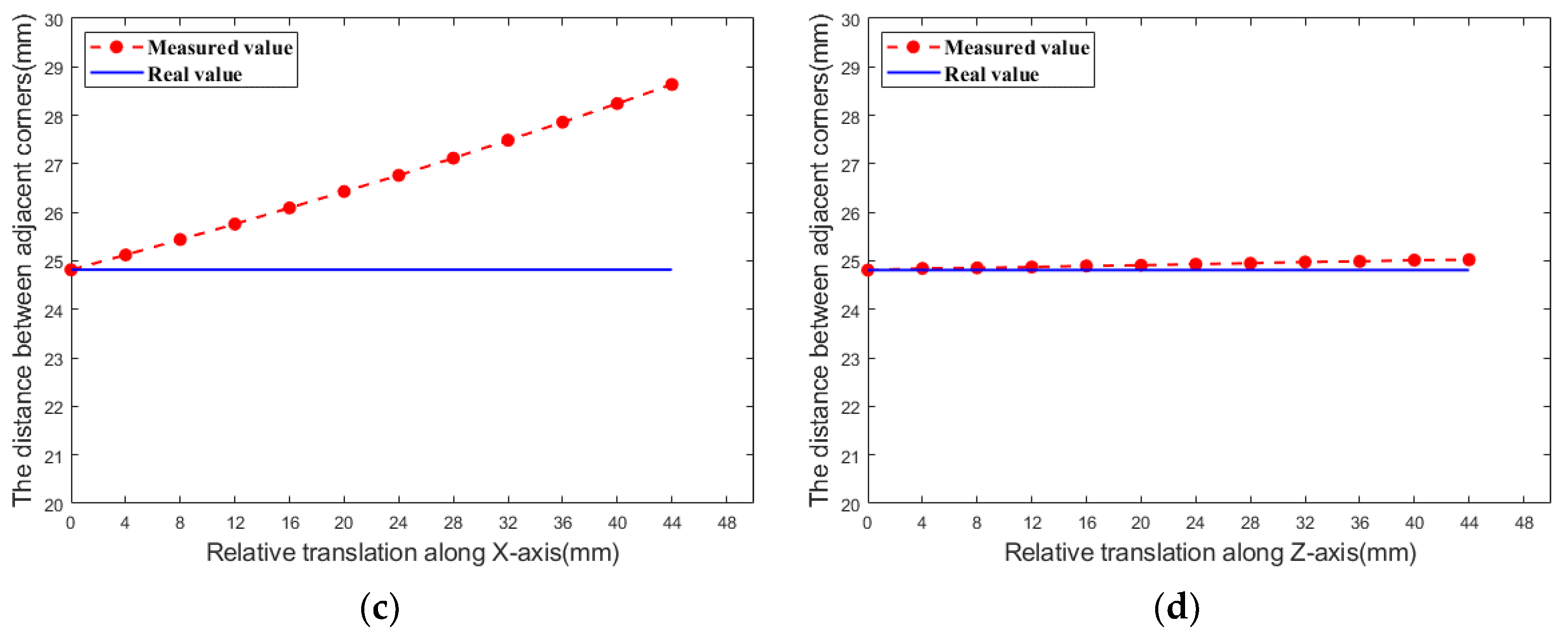
3.3. Relative Translations
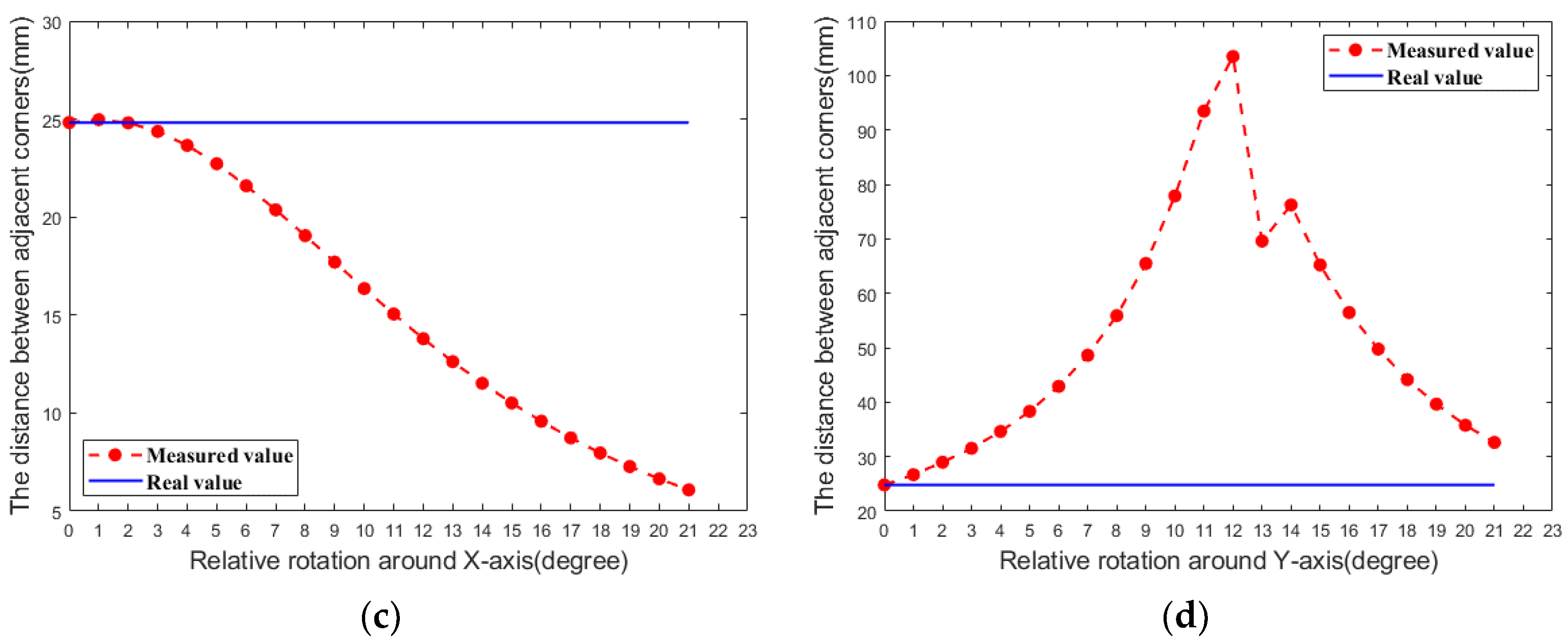
3.4. Relative Rotation
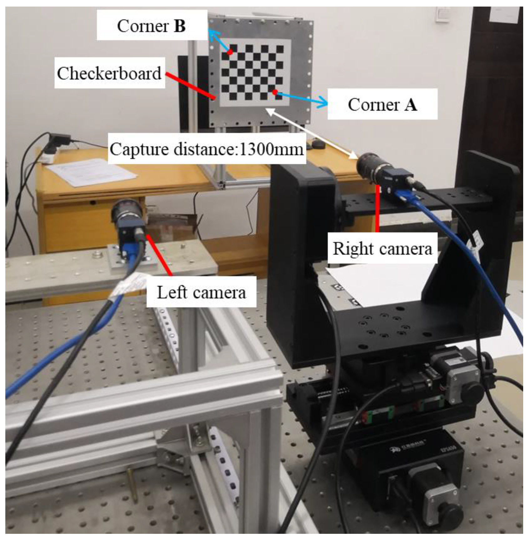
4. Experiments and Results
4.1. Identical Translation Experiment
4.2. Identical Rotation Experiment
4.3. Relative Translation Experiment
4.4. Relative Rotation Experiment
5. Conclusions
Author Contributions
Funding
Institutional Review Board Statement
Informed Consent Statement
Data Availability Statement
Conflicts of Interest
References
- Yu, C.; Chen, X.; Xi, J. Determination of optimal measurement configurations for self-calibrating a robotic visual inspection system with multiple point constraints. Int. J. Adv. Manuf. Technol. 2018, 96, 3365–3375. [Google Scholar] [CrossRef]
- Luo, Z.; Zhang, K.; Wang, Z.; Zheng, J.; Chen, Y. 3D pose estimation of large and complicated workpieces based on binocular stereo vision. Appl. Opt. 2017, 56, 6822–6836. [Google Scholar] [CrossRef]
- Wang, F.; Lü, E.; Wang, Y.; Qiu, G.; Lu, H. Efficient Stereo Visual Simultaneous Localization and Mapping for an Autonomous Unmanned Forklift in an Unstructured Warehouse. Appl. Sci. 2020, 10, 698. [Google Scholar] [CrossRef] [Green Version]
- Zhang, X.; Su, Y.; Gao, Z.; Xu, T.; Ding, X.; Yu, Q.; Zhang, Q. High-accuracy three-dimensional shape measurement of micro solder paste and printed circuits based on digital image correlation. Opt. Eng. 2018, 57, 054101. [Google Scholar] [CrossRef]
- Shao, X.; Dai, X.; Chen, Z.; Dai, Y.; Dong, S.; He, X. Calibration of stereo-digital image correlation for deformation measurement of large engineering components. Meas. Sci. Technol. 2016, 27, 125010. [Google Scholar] [CrossRef]
- Zhong, F.; Shao, X.; Quan, C. A comparative study of 3D reconstruction methods in stereo digital image correlation. Opt. Lasers Eng. 2019, 122, 142–150. [Google Scholar] [CrossRef]
- Guo, X.; Yuan, Y.; Suo, T.; Su, X.; Liu, Y.; Ge, Z. A novel deformation measurement method for ablation materials in combustion and ablation process. Opt. Lasers Eng. 2020, 134, 106255. [Google Scholar] [CrossRef]
- Su, Z.; Pan, J.; Zhang, S.; Wu, S.; Yu, Q.; Zhang, D. Characterizing dynamic deformation of marine propeller blades with stroboscopic stereo digital image correlation. Mech. Syst. Signal Process. 2022, 162, 108072. [Google Scholar] [CrossRef]
- Feng, D.; Feng, M.Q. Computer vision for SHM of civil infrastructure: From dynamic response measurement to damage detection—A review. Eng. Struct. 2018, 156, 105–117. [Google Scholar] [CrossRef]
- Dworakowski, Z.; Kohut, P.; Gallina, A.; Holak, K.; Uhl, T. Vision-based algorithms for damage detection and localization in structural health monitoring. Struct. Control. Heal. Monit. 2016, 23, 35–50. [Google Scholar] [CrossRef]
- Luo, L.; Feng, M.Q.; Wu, Z.Y. Robust vision sensor for multi-point displacement monitoring of bridges in the field. Eng. Struct. 2018, 163, 255–266. [Google Scholar] [CrossRef]
- Srivastava, B.; Anvikar, A.R.; Ghosh, S.K.; Mishra, N.; Kumar, N.; Houri-Yafin, A.; Pollak, J.J.; Salpeter, S.J.; Valecha, N. Computer-vision-based technology for fast, accurate and cost effective diagnosis of malaria. Malar. J. 2015, 14, 1–6. [Google Scholar] [CrossRef] [Green Version]
- Liu, T.; Burner, A.W.; Jones, T.W.; Barrows, D.A. Photogrammetric techniques for aerospace applications. Prog. Aerosp. Sci. 2012, 54, 1–58. [Google Scholar] [CrossRef]
- Liu, J.; Guo, P.; Sun, X. An Automatic 3D Point Cloud Registration Method Based on Biological Vision. Appl. Sci. 2021, 11, 4538. [Google Scholar] [CrossRef]
- Chen, L.; Huang, P.; Cai, J.; Meng, Z.; Liu, Z. A non-cooperative target grasping position prediction model for tethered space robot. Aerosp. Sci. Technol. 2016, 58, 571–581. [Google Scholar] [CrossRef]
- Li, W.; Shan, S.; Liu, H. High-precision method of binocular camera calibration with a distortion model. Appl. Opt. 2017, 56, 2368–2377. [Google Scholar] [CrossRef]
- Guan, B.; Yu, Y.; Su, A.; Shang, Y.; Yu, Q. Self-calibration approach to stereo cameras with radial distortion based on epipolar constraint. Appl. Opt. 2019, 58, 8511–8521. [Google Scholar] [CrossRef] [PubMed]
- Li, X.; Wu, Q.; Wang, Y. Binocular vision calibration method for a long-wavelength infrared camera and a visible spectrum camera with different resolutions. Opt. Express 2021, 29, 3855–3872. [Google Scholar]
- Satoru, Y.; Hiroki, U. Bridge deflection measurement using digital image correction with camera movement correction. Mater. Trans. 2012, 53, 285–290. [Google Scholar]
- Sohn, W.; Kehtarnavaz, N. Analysis of camera movement errors in vision-based vehicle tracking. IEEE Trans. Pattern Anal. Mach. Intell. 1995, 17, 57–61. [Google Scholar] [CrossRef]
- Chen, R.; Li, Z.; Zhong, K.; Liu, X.; Wu, Y.; Wang, C.; Shi, Y. A Stereo-Vision System for Measuring the Ram Speed of Steam Hammers in an Environment with a Large Field of View and Strong Vibrations. Sensors 2019, 19, 996. [Google Scholar] [CrossRef] [Green Version]
- Boden, F.; Lawson, N.; Jentink, H.W.; Kompenhans, J. Advanced in-Flight Measurement Techniques; Springer: Berlin, Germany, 2013; pp. 19–20. [Google Scholar]
- Lee, J.J.; Shinozuka, M. Real-Time Displacement Measurement of a Flexible Bridge Using Digital Image Processing Techniques. Exp. Mech. 2006, 46, 105–114. [Google Scholar] [CrossRef]
- Chang, C.-C.; Xiao, X.H. Three-Dimensional Structural Translation and Rotation Measurement Using Monocular Videogrammetry. J. Eng. Mech. 2010, 136, 840–848. [Google Scholar] [CrossRef]
- Won, J.; Park, J.-W.; Park, K.; Yoon, H.; Moon, D.-S. Non-Target Structural Displacement Measurement Using Reference Frame-Based Deepflow. Sensors 2019, 19, 2992. [Google Scholar] [CrossRef] [PubMed] [Green Version]
- Chen, J.G.; Davis, A.; Wadhwa, N.; Durand, F.; Freeman, W.T.; Büyüköztürk, O. Video camera-based vibration measurement for civil infrastructure applications. J. Infrastruct. Syst. 2016, 23, B4016013. [Google Scholar] [CrossRef]
- Zeinali, Y.; Li, Y.; Rajan, D.; Story, B. Accurate Structural Dynamic Response Monitoring of Multiple Structures using One CCD Camera and a Novel Targets Configuration. In Proceedings of the International Workshop on Structural Health Monitoring, Palo Alto, CA, USA, 12–14 September 2017; pp. 12–14. [Google Scholar]
- Yoon, H.; Shin, J.; Spencer, B.F. Structural Displacement Measurement Using an Unmanned Aerial System. Comput. Civ. Infrastruct. Eng. 2018, 33, 183–192. [Google Scholar] [CrossRef]
- Zhang, X.; Zeinali, Y.; Story, B.A.; Rajan, D. Measurement of Three-Dimensional Structural Displacement Using a Hybrid Inertial Vision-Based System. Sensors 2019, 19, 4083. [Google Scholar] [CrossRef] [Green Version]
- Kirmse, T. Recalibration of a stereoscopic camera system for in-flight wing deformation measurements. Meas. Sci. Technol. 2016, 27, 054001. [Google Scholar] [CrossRef]
- Xu, Y.; Zhao, Y.; Wu, F.; Yang, K. Error analysis of calibration parameters estimation for binocular stereo vision system. In Proceedings of the IEEE International Conference on Imaging Systems and Techniques (IST), Beijing, China, 22–23 October 2013; pp. 317–320. [Google Scholar]
- Yang, L.; Wang, B.; Zhang, R.; Zhou, H.; Wang, R. Analysis on Location Accuracy for the Binocular Stereo Vision System. IEEE Photon. J. 2018, 10, 1–16. [Google Scholar] [CrossRef]
- Kim, J.; Jeong, Y.; Lee, H.; Yun, H. Marker-Based Structural Displacement Measurement Models with Camera Movement Error Correction Using Image Matching and Anomaly Detection. Sensors 2020, 20, 5676. [Google Scholar] [CrossRef]
- Bier, A.; Leszek, L. Error analysis of stereo calibration and reconstruction. In Proceedings of The International Conference on Computer Vision/Computer Graphics Collaboration Techniques and Applications, Rocquencourt, France, 4–6 May 2009; pp. 230–241. [Google Scholar]
- Reu, P. A Study of the Influence of Calibration Uncertainty on the Global Uncertainty for Digital Image Correlation Using a Monte Carlo Approach. Exp. Mech. 2013, 53, 1661–1680. [Google Scholar] [CrossRef]
- Wang, Q.; Yin, Y.; Zou, W.; Xu, D. Measurement error analysis of binocular stereo vision: Effective guidelines for bionic eyes. IET Sci. Meas. Technol. 2017, 11, 829–838. [Google Scholar] [CrossRef]
- Su, Z.; Lu, L.; Dong, S.; Yang, F.; He, X. Auto-calibration and real-time external parameter correction for stereo digital image correlation. Opt. Lasers Eng. 2019, 121, 46–53. [Google Scholar] [CrossRef]
- Liu, X.; Liu, Z.; Duan, G.; Cheng, J.; Jiang, X.; Tan, J. Precise and robust binocular camera calibration based on multiple constraints. Appl. Opt. 2018, 57, 5130–5140. [Google Scholar] [CrossRef] [PubMed]
- Zhang, Z. A flexible new technique for camera calibration. IEEE Trans. Pattern Anal. Mach. Intell. 2000, 22, 1330–1334. [Google Scholar] [CrossRef] [Green Version]


Publisher’s Note: MDPI stays neutral with regard to jurisdictional claims in published maps and institutional affiliations. |
© 2021 by the authors. Licensee MDPI, Basel, Switzerland. This article is an open access article distributed under the terms and conditions of the Creative Commons Attribution (CC BY) license (https://creativecommons.org/licenses/by/4.0/).
Share and Cite
Liu, Y.; Ge, Z.; Yuan, Y.; Su, X.; Guo, X.; Suo, T.; Yu, Q. Study of the Error Caused by Camera Movement for the Stereo-Vision System. Appl. Sci. 2021, 11, 9384. https://doi.org/10.3390/app11209384
Liu Y, Ge Z, Yuan Y, Su X, Guo X, Suo T, Yu Q. Study of the Error Caused by Camera Movement for the Stereo-Vision System. Applied Sciences. 2021; 11(20):9384. https://doi.org/10.3390/app11209384
Chicago/Turabian StyleLiu, Yan, Zhendong Ge, Yingtao Yuan, Xin Su, Xiang Guo, Tao Suo, and Qifeng Yu. 2021. "Study of the Error Caused by Camera Movement for the Stereo-Vision System" Applied Sciences 11, no. 20: 9384. https://doi.org/10.3390/app11209384
APA StyleLiu, Y., Ge, Z., Yuan, Y., Su, X., Guo, X., Suo, T., & Yu, Q. (2021). Study of the Error Caused by Camera Movement for the Stereo-Vision System. Applied Sciences, 11(20), 9384. https://doi.org/10.3390/app11209384