Abstract
We investigated the fabrication and finishing of wall-profile machining by wire and arc additive manufacturing (WAAM) employing plasma welding with Ti-6Al-4V wire. We fabricated and integrated a local shield and a cover for the area below the local shield to achieve higher shielding ability. The tensile strength of the fabricated object met the forging standard for Ti-6Al-4V, but elongation was about 7%. We also focused on the possibility of reducing the cutting force and increasing the efficiency of the finishing process by cutting workpieces softened by high temperature immediately after the deposition process. We investigated the cutting force and tool wear of the fabricated objects heated to 300 °C using ceramics tools. Results showed that although the cutting force was reduced at high temperature, the wear rate of the tools was high, and the increase in cutting force due to wear was significant.
1. Introduction
Additive manufacturing (AM), which enables rapid modeling of complex shapes, reduces manufacturing costs, and has high functionality, has recently received increased attention [1]. AM technology can create thin-layer 2D data from designed 3D CAD data, fabricate them in order, and acquire the 3D CAD data. It enables the quick creation of complex structures close to the final shape from 3D CAD data designed on a PC. If the design must be changed, it can be immediately remodeled. In this paper, we focused on wire and arc additive manufacturing (WAAM) using a plasma arc as a heat source and conducted the deposition and finishing processes with milling for Ti-6Al-4V.
Ti-6Al-4V components are often used for aircraft parts due to their high specific strength and corrosion resistance [2,3]. Ti-6Al-4V components made by AM technology have a better yield rate than forged products, because they can be produced in near-net shapes. Cost reduction is expected by adopting parts created with AM technology. Ti-6Al-4V is a difficult-to-cut material, and the amount of cutting can be significantly reduced by fabricating it into a near-net shape.
Research on the AM of Ti-6Al-4V is actively underway. Oxidation during the process is a challenge because titanium alloy will easily oxidize, which deteriorates the part’s mechanical properties. Zhou et al. examined fabricating Ti-6Al-4V using a chamber filled with argon gas [4]. The mechanical properties of the fabricated objects were altered due to the deposition path. Specimen vertical to the deposition path has better elongation than horizontal specimens. β grains tend to grow in the direction vertical to the deposition path in objects fabricated by WAAM, which is considered to be one of the causes of the decrease in ductility in horizontal specimens. Ding et al. fabricated Ti-6Al-4V objects using a local shield, and investigated the effective amount of argon (Ar) gas needed and the position of the local shield [5]. They found that the oxygen (O2) concentration directly under the local shield tended to decrease as Ar gas supplied increased. Bermingham et al. also fabricated Ti-6Al-4V objects using a local shield to consider the mechanical properties and oxide layer thickness with and without the shield [6]. The elongation improved about 1% (from about 9 to 10%) by using a local shield. In addition, there was no significant difference between tensile strength and a 0.2% proof stress. The O2 content of the fabricated object was reduced from 0.10 to 0.08% by the local shield, proving that fabricated objects with less oxidation could be obtained with the shield.
Ti-6Al-4V objects were fabricated by plasma welding, electron beam welding, and powder bed fusion (PBF), and the mechanical properties of the fabricated objects by tensile tests were examined [7,8,9]. Compared to the ASTM B381-13 value, tensile strength was higher, while elongation was about 3% lower than the ASTM standard. They also clarified that the mechanical properties of fabricated objects whose oxidation was suppressed using the local shield were not significantly different from those made by other methods.
WAAM components have irregularities on each layer, so they must be finished in order to serve as mechanical parts. Ti-6Al-4V is a difficult-to-cut material due to its low thermal conductivity. A ceramic tool can be used for high-speed cutting, because it has high high-temperature strength. Ceramic tools include alumina-based ceramics [10,11], silicon nitride-based ceramics [12,13], cermet [14,15], and sialon-based ceramics [16,17]. These applications have been reported.
Zhang et al. performed high-speed milling of AM components using silicon nitride-based ceramic tools [12,13]; a Ti-6Al-4V workpiece made by direct metal laser sintering was grooved at room temperature. Experiments were conducted by changing the feed rate. The group clarified that when the feed rate was 0.05 mm/tooth, the cutting force was about 100 N, and the surface roughness was about 0.2-μm smaller than with 0.09 mm/tooth. Moreover, they found that when a silicon nitride-based ceramic tool was used, the main forms of wear were adhesive and diffusion wear.
Bermingham et al. carried out laser-assisted milling using PVD-coated carbide tools [18]. By preheating the work material side only with a laser to about 300 °C at an output of 50 W, and about 500 °C at a laser output of 150 W, they aimed to soften the material and improve the tool life. The study compared dry milling at room temperature, high-temperature milling with two types of laser output, and hybrid milling that combined preheating with a laser and minimum quantity lubrication (MQL). With dry machining, when the cutting speed was 69 m/min, tool life was increased about 10% with high-temperature milling compared to dry milling at room temperature, but tool life was less than half when the cutting speed exceeded 90 m/min. Tool life was most improved in hybrid machining in which MQL and laser assist were combined.
This background clarifies the need to establish a high-efficiency process for fabricating objects of titanium alloy that includes the finish cutting in addition to an additive process with no welding defects, higher shape accuracy, and low oxidation. In this paper, we used a plasma arc with high arc directivity and can form a straight bead without distortion. To suppress the oxidation of deposited materials, we supplied inert gas using a developed local shield that covered the deposition area. We then clarified the mechanical properties of the deposited object by tensile test.
After the WAAM deposition process, a machining process is necessary to achieve higher geometrical accuracy of the fabricated object. We therefore conducted a cutting experiment at a high temperature. This was because, on the hybrid machine that combines WAAM process and machining center, the machining process can be conducted immediately after deposition, similar to laser-assisted milling. The machining characteristics of titanium alloy deposited by WAAM at high temperature, however, remain unclear. We also investigated the effect on cutting force and tool wear under high-temperature milling using ceramic tools. In the deposition process, the welding point is melted at a temperature of about 1600 °C. Since Ti-6Al-4V oxidizes at 500 °C or higher, it is necessary to cool it to about 400 °C in an atmosphere of an inert gas such as Ar. Even if manufacturing were assumed using a hybrid AM machine that can alternately perform the cutting and additive processes, it would be expected that the temperature would drop further from fabricating to cutting. Therefore, the high temperature of the fabricated object was determined to be about 300 °C. Silicon nitride-based ceramic tools, which have excellent high-temperature strength and wear resistance, were used as the insert. The fabricated object of Ti-6Al-4V was cut with ceramic tools to reveal the effect of preheating temperature on cutting resistance and tool life.
2. Experimental Procedures
2.1. WAAM Machine with Plasma Arc Welding Torch
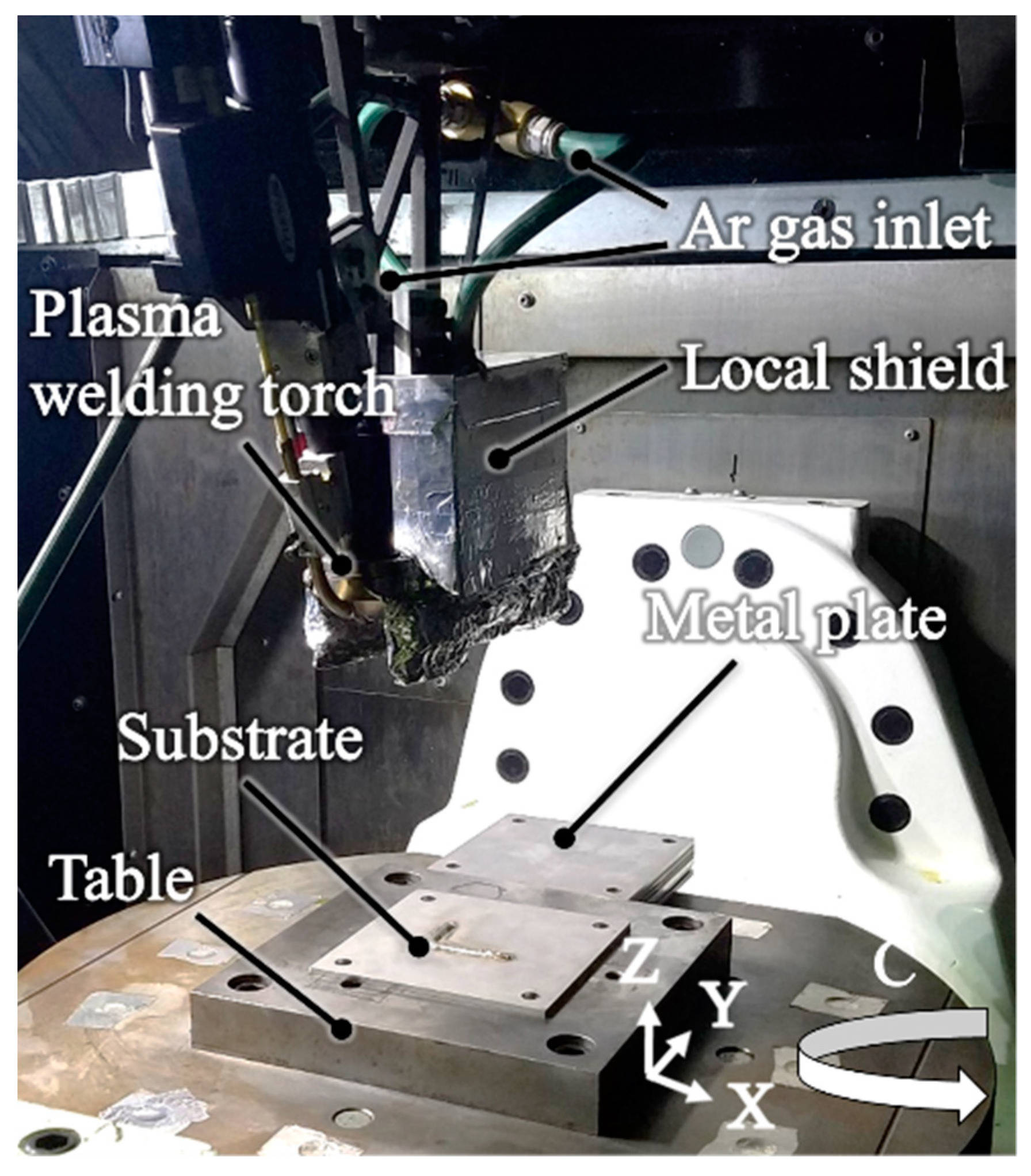
A plasma arc welding torch was installed in a 5-axis machining center (Yamazaki Mazak, VARIAXIS j-600/5X). Figure 1 shows the building area of the machine. With plasma arc welding, a tungsten electrode serves as the cathode, the base metal serves as the anode, and a straight bead can be formed without unintended arc discharge and with high arc directivity. The wire is supplied from the front side of traveling. The welding torch is fixed on the head, which cannot rotate or tilt then the work table has a rotation and tilt axis. During the deposition of one layer, the feed direction is maintained in the Y direction, controlling the C-axis with the X-axis.

Figure 1.
The 5-axis wire arc additive manufacturing machine.
2.2. Local Shielding to Inhibit Oxidation during the Deposition Process
The Ti-6Al-4V is an active metal that reacts with O2 in the atmosphere at 500 °C or higher, leading to embrittlement. When shielding gas is supplied from the torch, the vicinity of the molten pool is protected, but it is difficult to keep shielding the built beads while at a higher temperature. This study developed a local shield that could shield the bead after deposition over 100 mm. Ar gas was supplied at a concentration of 99.995% during fabrication. O2 concentration at the area directly under the local shield before fabricating was kept to 0.05% or less. O2 concentration was measured with a zirconia O2 concentration meter.
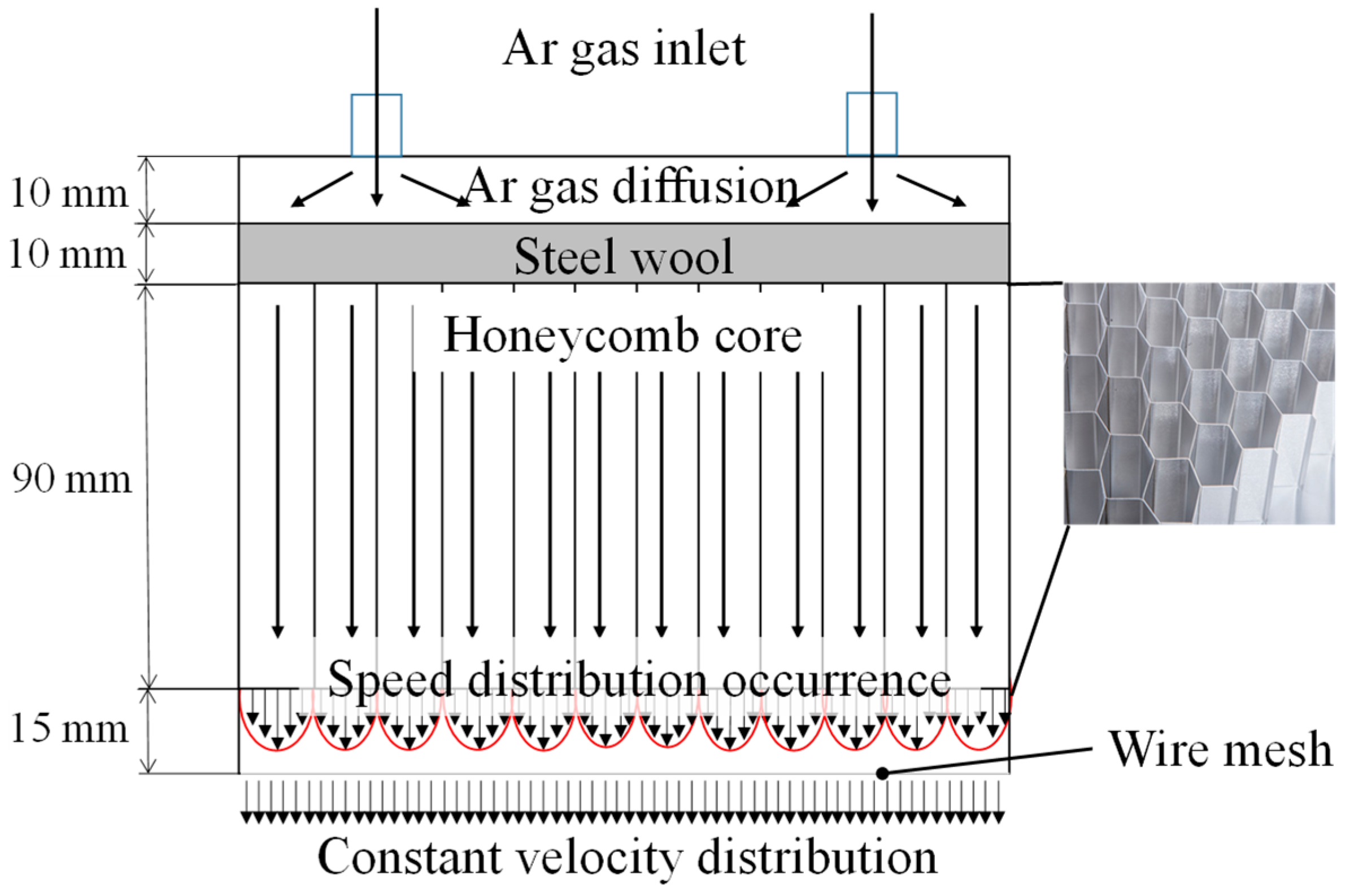
Figure 2 shows the shape of the local shield developed in this study. The overall dimension was 180 mm in horizontal length, 80 mm in width, and 125 mm in height. To configure the local shield, we referred to the paper by Bermingham et al. [6]. Ar gas was supplied from two holes on the top of the local shield using tubes. The supplied gas was diffused by a layer of steel wool with thickness of 10 mm, and rectified downward by the rectifying action of the honeycomb core located in the lower layer. The cell size of the hexagonal honeycomb core was 6.35 mm. Immediately below the honeycomb core, a velocity field was generated according to the distance from the wall due to viscosity, so the Ar gas was passed through a wire mesh with a spatial ratio of 0.37 to equalize its velocity and supply it directly above the shaped bead. In addition, the cover shown in Figure 3 was attached to the lower part of the local shield to protect the space from the lower part of the local shield to the substrate. This blocked off the area under the local shield from the outside, making it easier to reduce the O2 concentration in the high-temperature deposition part.
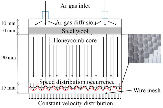
Figure 2.
Internal structure of the local shield.
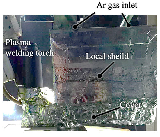
Figure 3.
Local shield with cover.
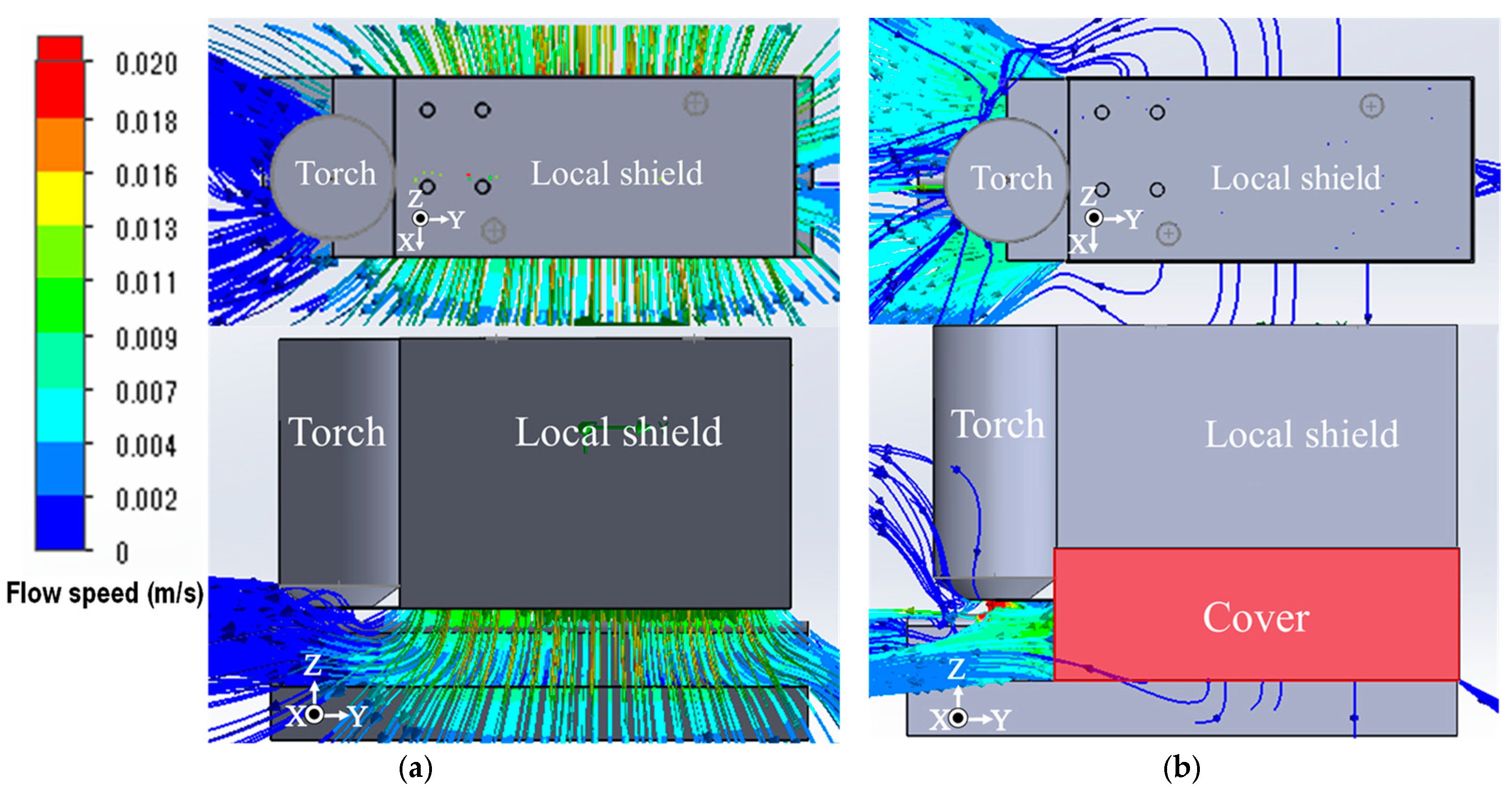
To evaluate the effectiveness of the newly attached cover underneath the local shield, flow analysis was performed using general-purpose fluid analysis software. Figure 4 presents the results. When the local shield was not equipped with the cover underneath it (Figure 4a), Ar gas flowed underneath the shield, surrounded the high-temperature region of built beads, and the concentration of Ar gas was low. On the other hand, with the cover underneath the local shield, Ar gas filled the area surrounded by the cover and substrate and was discharged from open space to the left (Figure 4b). We therefore expected that the concentration of Ar gas around the welding point and high temperature region of the built bead would be kept high. In other words, this local shield acted as a semi-closed chamber. The shield was attached to a plasma welding torch as shown in Figure 3.

Figure 4.
Flow velocity field of Ar gas supplied downward from local shield. (a) Without cover underneath local shield; (b) With cover underneath the local shield.
2.3. Fabrication of the Tensile Test Specimen
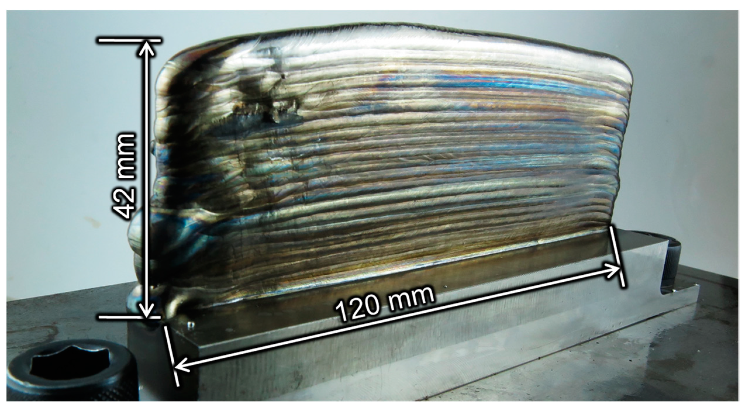
Test specimens for the mechanical property evaluation and milling test were built using the conditions listed in Table 1. Single beads were laminated to form a wall 120-mm long and 42-mm high. Its thickness was between 7.6 mm and 7.8 mm. The torch travel direction was alternated for each layer. Figure 5 shows the fabricated object. Temper color due to oxidation can be seen on the side surface of the object, but is pale bluish purple or gold, which is considered an acceptable condition for titanium alloy welding. Meanwhile, the upper part of the object was silvery white. We believe that the time of exposure to high temperatures affected the degree of oxidation. The top layer was exposed to high temperatures only once when it was deposited. During the deposition process, the temperature of the lower layers would also rise. Then the part except the top region was exposed to high-temperature several times when the upper layers were deposited.

Table 1.
Fabricating conditions of the additive process for tensile test specimen.
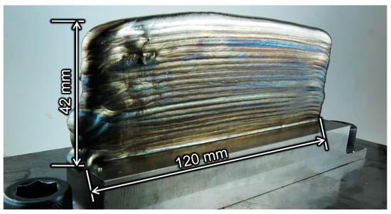
Figure 5.
Specimen fabricated by WAAM for tensile test.
2.4. High Temperature Milling of Fabricated Object
This paper investigates the cutting characteristics of titanium alloy parts fabricated by WAAM at high temperatures assuming that the fabricated parts are machined and finished immediately after fabrication using a machine that combines the AM process with the post-process cutting. However, the actual cutting test was conducted by heating the fabricated specimens to the specified temperature on the machining center, because the setup for immediate cutting was not available.
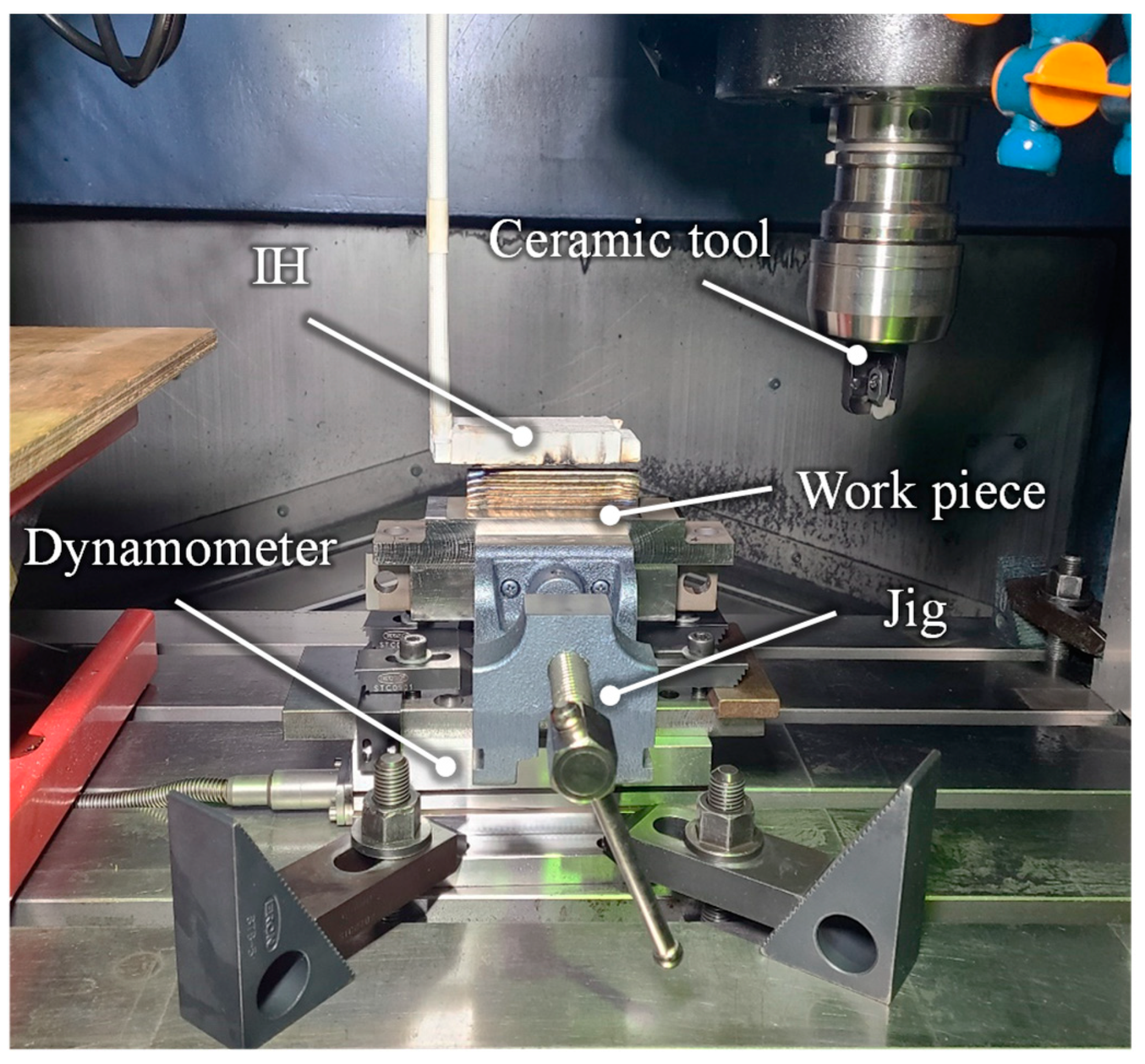
Figure 6 shows the experimental setup of milling test. A machining center (Yamazaki Mazak, FJV-250 UHS) was used for the high-temperature milling test. We used an induction heater (IH) to elevate the temperature of the fabricated object to about 300 °C to perform the high-temperature milling. In the experiment, a dynamometer (Kistler 9257B), a vise, and an object fabricated by WAAM were attached to the table of the machining center to measure the cutting force. A thermal camera (FLIR T650s) was used to confirm the heating and cutting temperature. Emissivity was set to 0.42 when measuring the temperature with the thermal camera; this was to ensure the temperature of the surface coated with Black-body spray coincided with that of the titanium alloy surface.
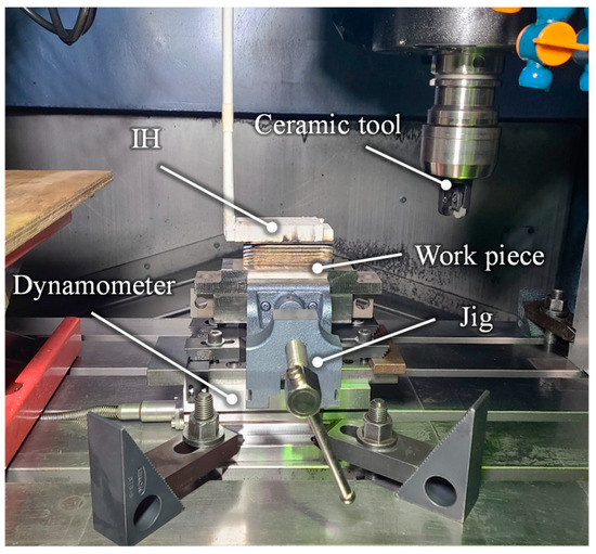
Figure 6.
Experimental setup for milling test.
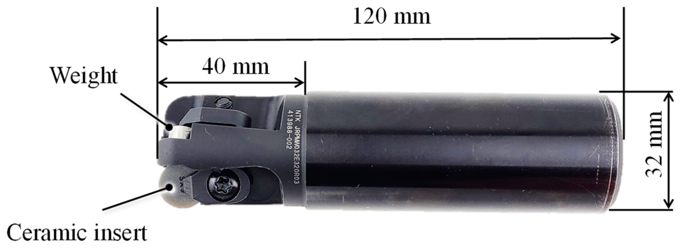
Figure 7 shows the ceramic tools used in the experiment. The tool insert was a round-type silicon nitride-based ceramic insert (NGK Spark Plug Co., Ltd., RPGN120400T00525: SX9), which has excellent high-temperature strength and wear resistance. The tool diameter was 32 mm. A 3-flute cutter body was used, but only one insert was attached to the cutter body to measure tool wear and to eliminate the influence of tool runout. The other insert mounting positions gripped a weight equal to the insert to suppress weight imbalance.
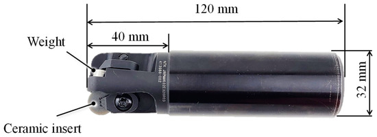
Figure 7.
Cutting tool used for milling test.
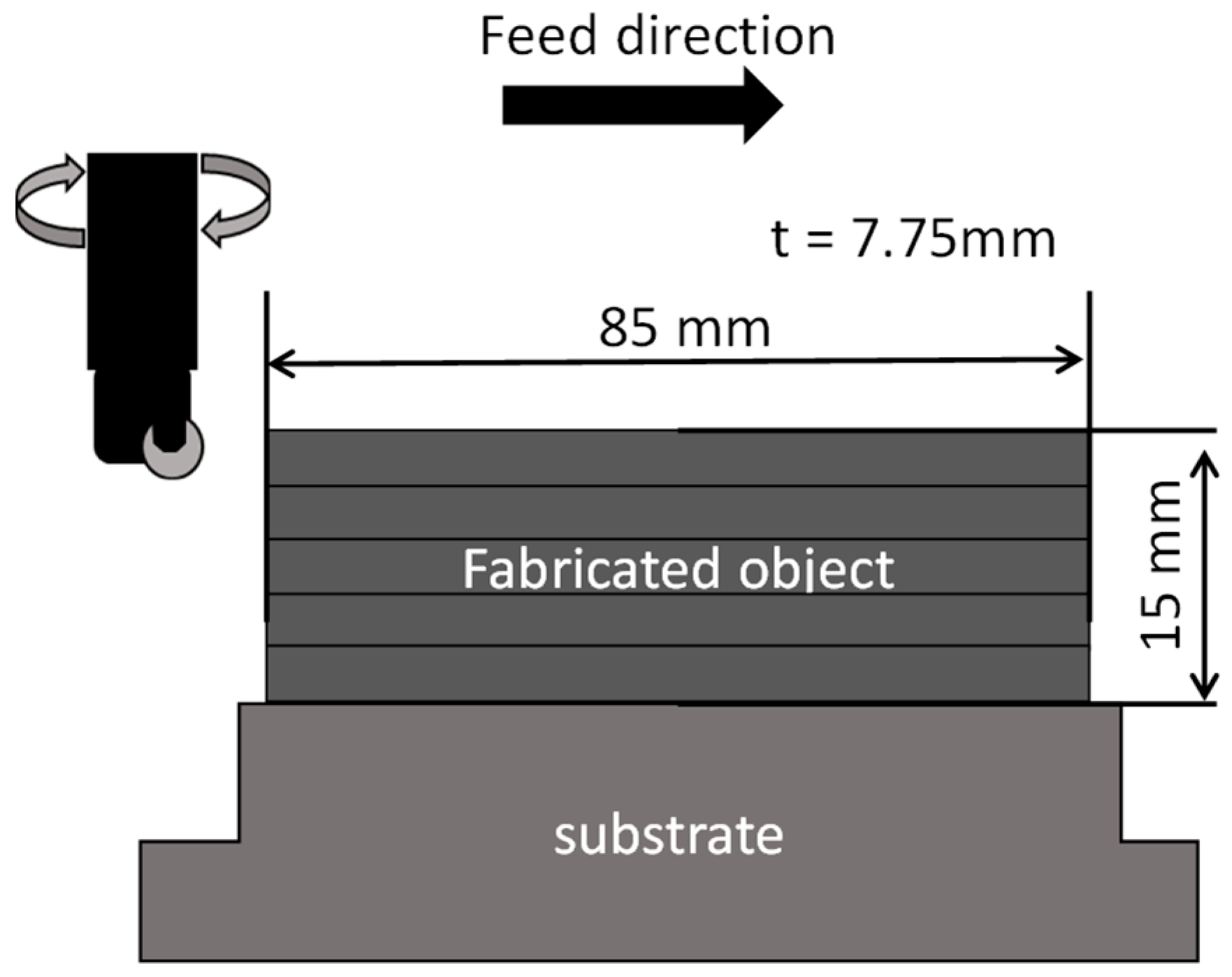
Figure 8 is a schematic diagram of how the fabricated object was milled; Table 2 lists the cutting test conditions; and Table 3 shows the welding conditions for the test object to be machined. The fabricated object was a 10-layer wall shape, 7.75-mm wide, 85-mm long, and 15-mm high. The top surface of the specimen was machined in the test. To reduce the fabricating height error, the feed rate within one path was changed as detailed in Table 4. Since the ends of the fabricated object were not uniform in shape, they were cut off by wire electric discharge machining so that the amount of cutting could be constant during milling. The sides of the fabricated object have the unevenness characteristic of WAAM, but the width was within the range of 7.67–7.81 mm. The cutting distance for each pass was 20 mm, and the cutting force from the start of milling to 0.5 s was defined as the initial stage cutting force. The average values of the maximum cutting forces in the range of 0.2–0.5 s were compared. The heating temperature during milling was set at room temperature, 50, 100, 150, 200, 250 and 300 °C.

Figure 8.
Schematic of the milling test.
Table 2.
Cutting test condition under varying workpiece temperature.
Table 3.
Fabricating conditions of the additive process for cutting test specimen.
Table 4.
Change of elemental composition before and after WAAM process measured with an oxygen/nitrogen analyzer and EDX.
3. Mechanical Properties of the Built Titanium Alloy
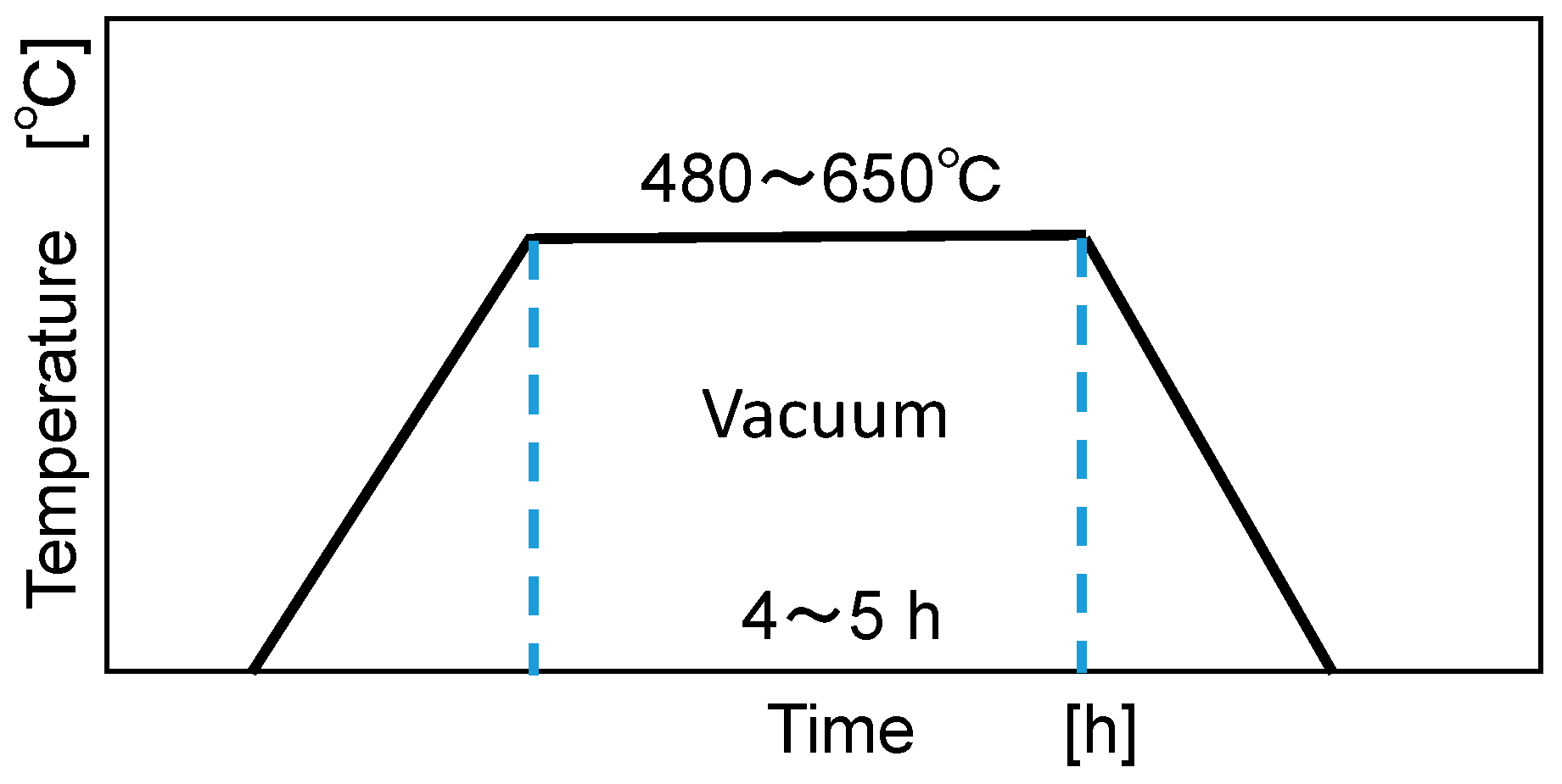
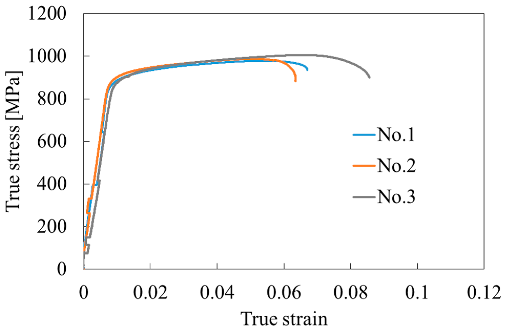
Figure 9 shows the dimensions of the tensile test piece. Since the test piece might be deformed due to residual stress generated during the deposition process, the built object was subjected to stress-relief annealing under the conditions shown in Figure 10. The test piece was then cut out by wire electric discharge machining. The tensile direction was parallel to the torch traveling direction. We do not consider anisotropy between the deposition direction and the torch traveling direction here. The applied load during the tensile test was measured by the load cell at the upper crosshead of the tensile testing machine, and the strain and elongation were measured with both a strain gauge attached to the tensile test specimen and a digital extensometer. The crosshead moving speed was 5.0 mm/min. Figure 11 shows the true stress–strain diagram of each test piece. The tensile strength of each test piece was between 931 and 946 MPa; the 0.2% proof stress was between 891 and 892 MPa; and the elongation ranged from 6.6–8.9%. According to JIS H4657 of the Ti-6Al-4V forging material standard, tensile strength, 0.2% proof stress, and elongation are 895 MPa or more, 825 MPa or more, and 10% or more, respectively. Based on this standard, the tensile strength and 0.2% proof stress met this required standard for forging material, but the elongation was slightly below the standard value. Elemental analyzers then evaluated the composition of the test specimen. An oxygen/nitrogen analyzer (HORIBA, Ltd., EMGA-900) was used to analyze light elements such as O2, and an EDX (AMETEK, EDAX) was used to analyze other elements. We considered that one of the causes of the slightly smaller elongation was the influence of O2 concentration in the deposited object. The local shield and cover were developed to reduce the O2 concentration in the fabricating atmosphere, but their effect might have been limited. Table 4 presents the elemental analysis results of the specimen, and the wire material supplied to the WAAM process. For reference, values for the aircraft standard AMS4911 for Ti-6Al-4V are also given in the table. The O2 concentration in the test specimen was 0.232%, slightly higher than the upper limit of O2 concentration of 0.20% for the aircraft standard ASM4911 of Ti-6Al-4V. The slight difference in the oxygen concentration in the parts, 0.2% and 0.23%, may be one of the reasons for the reduction in elongation. Nevertheless, the O2 concentration might be sensitive to elongation. The values of N and H in the modeled object were slightly larger than those in the wire material, but not by a problematic amount. The amount of Al was also smaller than the value in the wire material. It is considered that vaporization occurred under the high-temperature state in the plasma during the process, resulting in a decrease of component amounts.
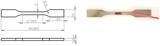
Figure 9.
Dimensions of the tensile test piece and its picture with strain gauge.
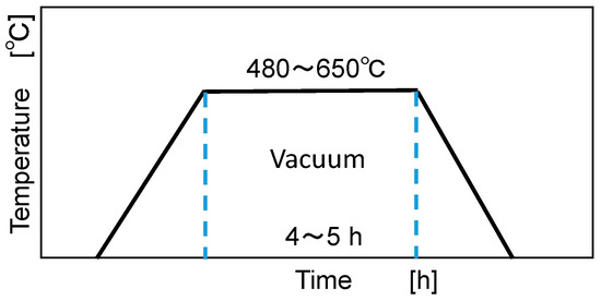
Figure 10.
Diagram of the stress-relief annealing process.
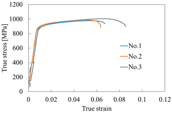
Figure 11.
True stress—strain diagram of the test pieces.
Finally, we compared the mechanical properties of the Ti-6Al-4V objects and other metal additive manufacturing. The comparison targets were as follows: (1) WAAM with a local shield and cover supplying Ar gas shown in this paper; (2) WAAM process using the same equipment but with the whole working area enclosed in an Ar-filled chamber to keep O2 concentration to less than 1% (tested by the authors); (3) WAAM with local shield without a cover supplying Ar gas by Lin et al. [7]; (4) electron beam + wire supplied in the vacuum chamber by Xu et al. [8]; and (5) PBF based on selective laser melting by Dutta et al. [9] Table 5 lists the tensile strength, 0.2% proof stress, and elongation for each method. The values of the forging material standard JIS H 4657 are given as a reference.
Table 5.
Comparison of mechanical properties of different AM processes of Ti-6Al-4V.
Compared to the Lin et al. case using a local shield, the tensile strength and 0.2% proof stress were slightly lower, and the breaking elongation slightly larger with the lower cover added to the local shield. On the other hand, it can be seen that elongation exceeded 10% in the case where the building area was a closed chamber to control O2 concentration, and in the vacuum case of the electron beam + wire. For reference, in the case of the PBF method, the tensile strength showed a high value of 1100 MPa, but the elongation was as low as 7%. In the case of powder material, since the surface area is large relative to the volume of the material, it is necessary to consider antioxidation in the stock state. In that respect, it is advantageous that the wire’s surface area/volume ratio in the material state is small. Since O2 concentration is kept low when a closed chamber or vacuum atmosphere is used, it leads to higher elongation, over 10%, whereas a local shield did not achieve elongation over 10%. However, fabricating larger objects requires a larger chamber volume. A local shield is easy to install for a larger WAAM machine. Moreover, on the hybrid machine combining the additive process and subtract machining processes, it is also easy to apply the local shield.
4. High-Temperature Cutting of the Titanium Alloy Object Built by WAAM
4.1. Relationship between Workpiece Temperature and Initial Cutting Force
We conducted the milling test on the fabricated object under high temperature and room temperature using a ceramic tool, and investigated the effect on the initial cutting force.
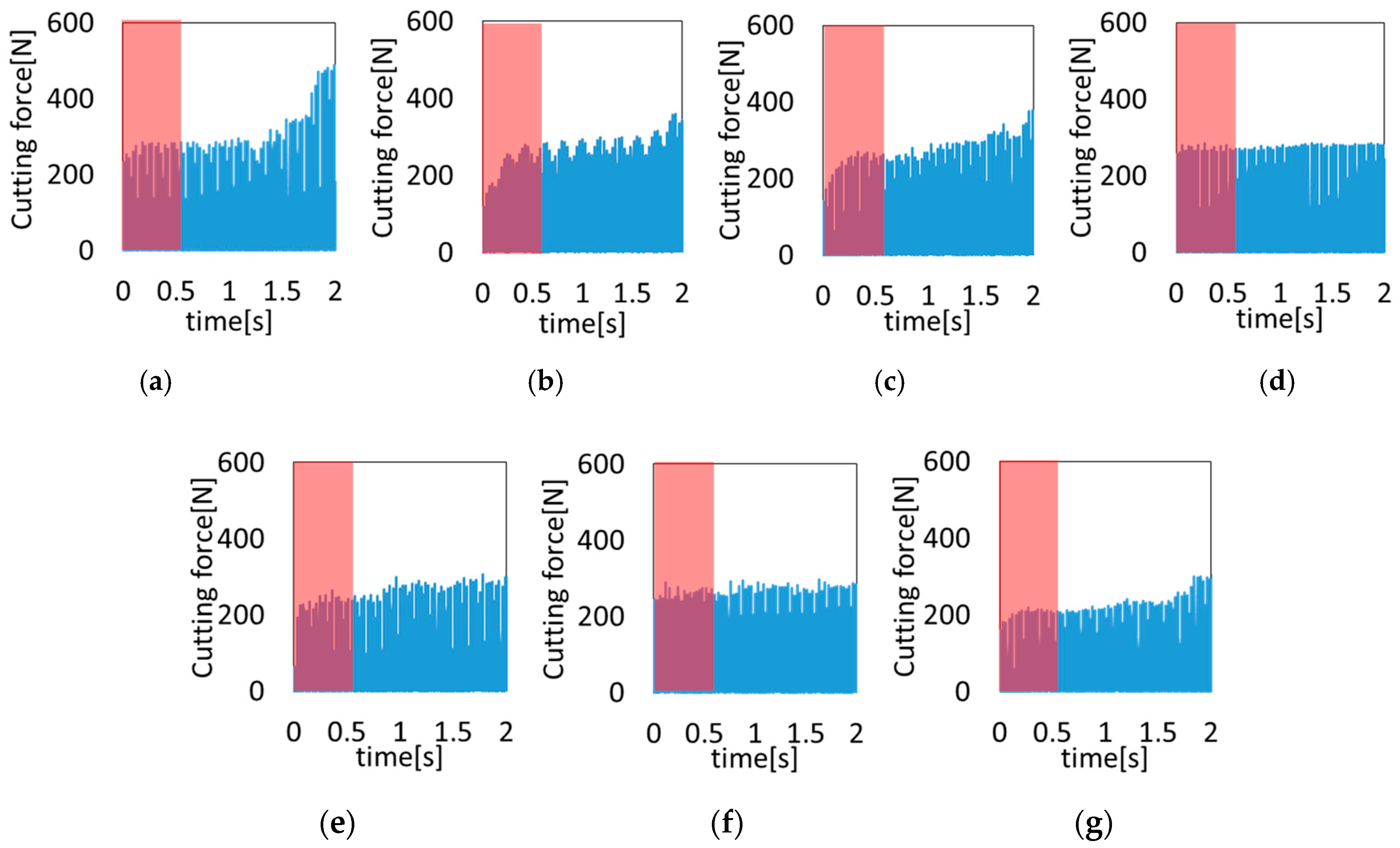
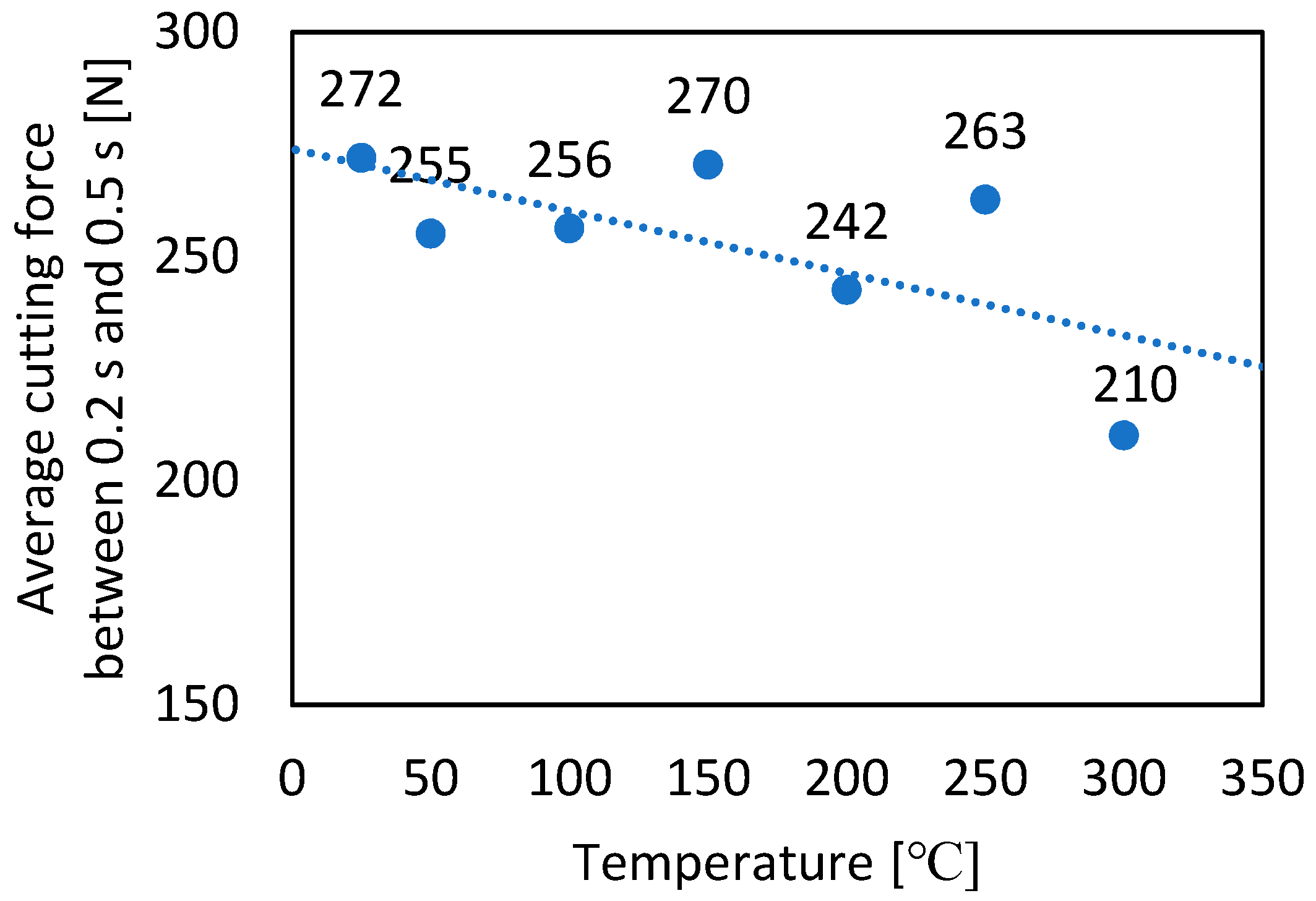
Figure 12 shows the transition of the cutting force at each heating temperature. The range shaded in red in Figure 12 indicates 0–0.5 s. It can be seen that the cutting force did not change significantly up to 1.5 s at any heating temperature. Figure 13 shows the average value of the maximum cutting force from 0.2–0.5 s at each heating temperature. The figure reveals that the initial cutting force between room temperature and 250 °C was around 260 N, which decreased with increasing heating temperature. When the temperature was elevated to 300 °C, the initial cutting force was 210 N, about 23% lower than that at room temperature. In the high-speed milling of Ti-6Al-4V fabricated objects, it would be possible to reduce the cutting force at a higher temperature if the amount of tool wear was small.
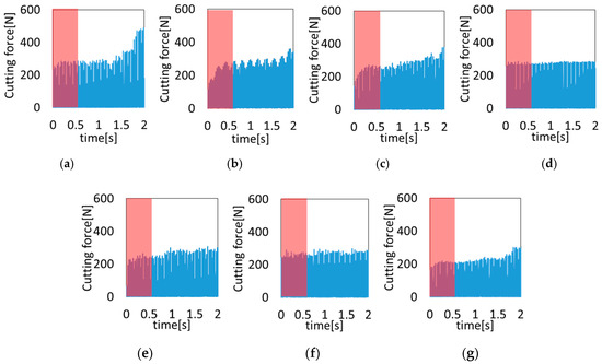
Figure 12.
Cutting force transition affected by the heating temperature. (a) R.T.; (b) 50 °C; (c) 100 °C; (d) 150 °C; (e) 200 °C; (f) 250 °C; (g) 300 °C.

Figure 13.
Effect of workpiece temperature on cutting force of WAAM Ti-6Al-4V.
4.2. Effect of Tool Wear Progression on Cutting Force
We demonstrated that the initial cutting force could be reduced by about 23% when the heating temperature was 300 °C compared to room temperature. We then milled the Ti-6Al-4V fabricated object at 300 °C using IH and investigated the changes in tool wear and cutting force as the cutting distance progressed. The heating temperature was set to 300 °C and compared with the case at room temperature. The fabricated object was first heated to about 500 °C, and then cooled to 300 °C before the cutting was conducted. A total of nine paths were performed, and tool wear and cutting force were measured at the third, sixth, and ninth paths. When the feed rate was 0.15 mm/tooth, the cutting length after three passes was about 14 m; at six passes, about 28 m; and at nine passes about 42 m. We alternated the feed direction, and the center of the tool was located on the left side of the workpiece. Then the milling was performed on the down-cut side, where the chipping of the tool is suppressed.
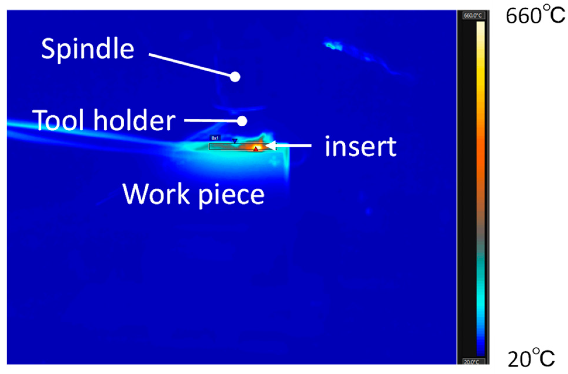
Figure 14 presents one example of an image captured by the thermal camera (FLIR, T650sc). With the camera, we were able to measure the temperature distribution and the maximum temperature in the frame. The maximum temperature near the tool edge was considered the cutting temperature. The spatial resolution of the thermal camera was 0.68 mrad. The cutting temperature was 158 °C on the third pass, 179 °C on the sixth pass, and 187 °C on the ninth pass when the workpiece temperature was room temperature. When heated to 300 °C, the cutting temperature was 530 °C on the third pass, 538 °C on the sixth pass, and 581 °C on the ninth pass.

Figure 14.
Example of the thermal image during the milling.
Figure 15 shows the transition of the cutting force of each pass. The light blue indicates the cutting force when milling at room temperature, and the orange represents the cutting force at 300 °C. Even when the number of cutting passes increased, the cutting force did not increase much. However, the cutting force at room temperature was around 900 N, smaller than at 300 °C when the cutting force was around 1000 N.
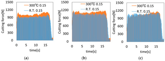
Figure 15.
Transition of cutting force of the fabricated object at 300 °C and room temperature. (a) Third pass; (b) Sixth pass; (c) Ninth pass.
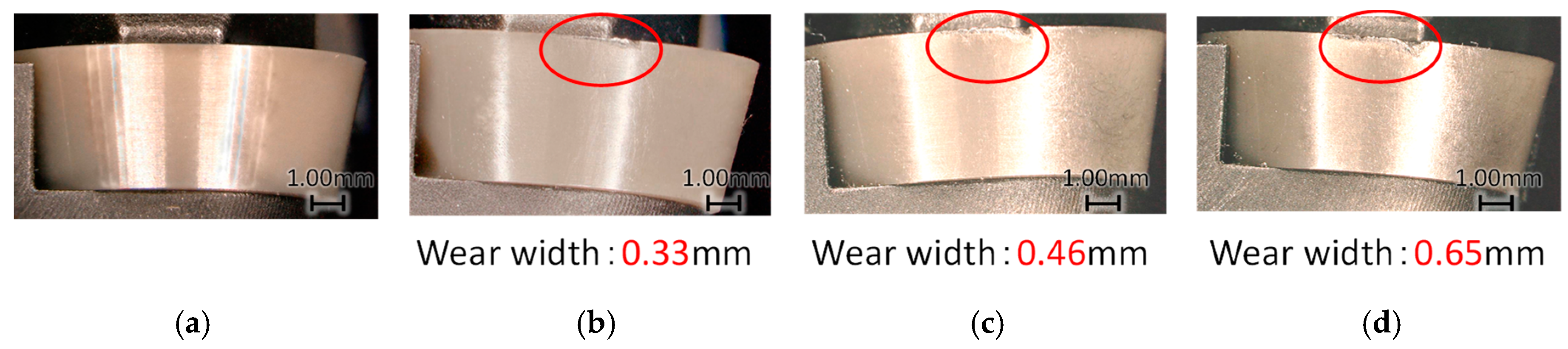
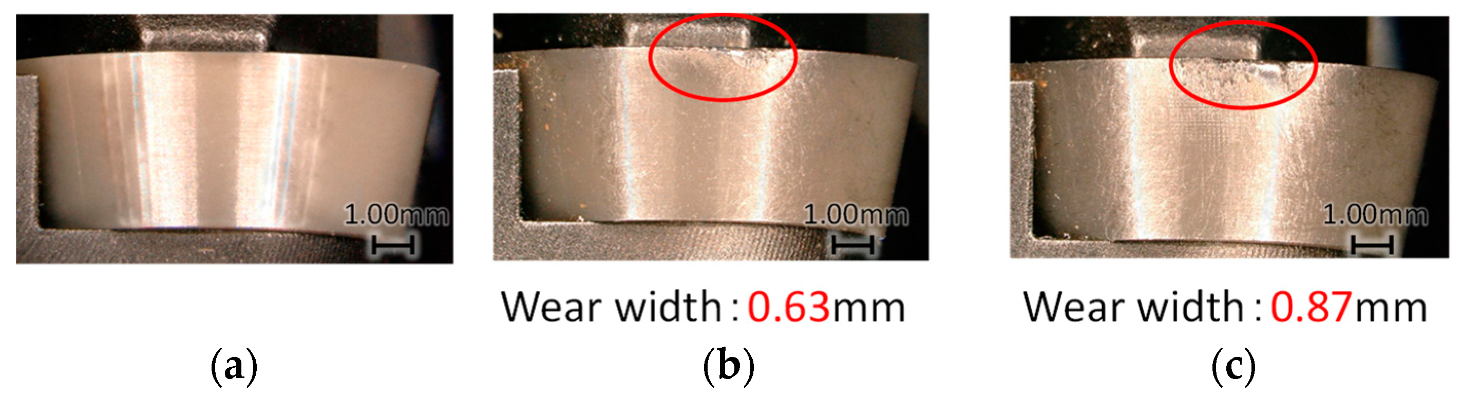
Figure 16 and Figure 17 show the flank wear width during milling at room temperature and 300 °C, respectively. There is no photograph for the 6th pass at 300 °C, because the whole view was not recorded. When milling at room temperature, the flank wear width increased to 0.33 mm, 0.46 mm, and 0.65 mm in steps of three passes. In contrast, it increased to 0.63 mm, 0.72 mm, and 0.87 mm when the workpiece was heated to 300 °C. Wear width was larger during high-temperature milling in all paths.
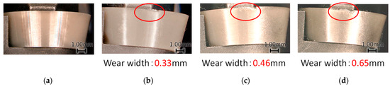
Figure 16.
Tool wear progress at room temperature. (a) New tool; (b) After third pass; (c) After sixth pass; (d) After ninth pass.
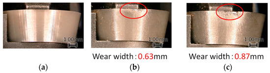
Figure 17.
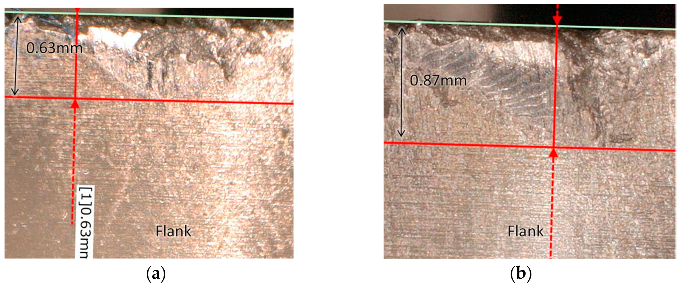
Tool wear progress for workpiece heated to 300 °C. (a) New tool; (b) After third pass; (c) After ninth pass.
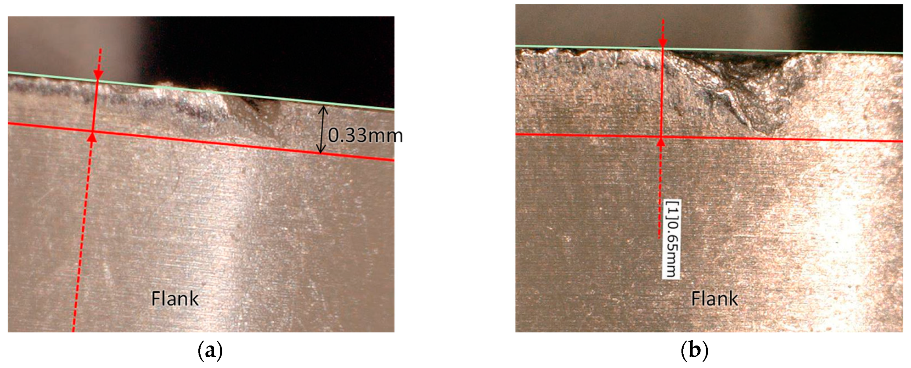
Figure 18 and Figure 19 show enlarged tool flanks on the third and ninth paths at room temperature and 300 °C, respectively. Only the boundary wear grew during room-temperature milling, but both boundary and flank wear increased during high-temperature milling. It should be noted that tool wear at 300 °C was almost comparable to the case after the ninth pass at room temperature. Higher temperature promoted larger tool wear, which in turn led to higher cutting force at 300 °C. Although the initial cutting force for a cutting time shorter than 0.5 s was smaller at 300 °C, the cutting force after the third path increased with the tool wear progression. This was because the increase in cutting force due to tool wear was greater than the decrease in cutting force due to the softening of the titanium alloy by temperature increase.

Figure 18.
Enlarged views of tool wear at room temperature. (a) Third pass; (b) Ninth pass.
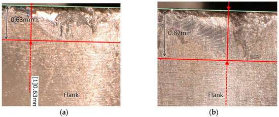
Figure 19.
Enlarged views of tool wear for workpiece heated to 300 °C. (a) Third pass; (b) Ninth pass.
5. Conclusions
In wire and arc additive manufacturing (WAAM), we showed that our newly developed local shield and cover could be used to fabricate titanium alloy parts successfully, and we investigated their mechanical properties. In addition, the cutting force and tool wear of the titanium alloy specimens were investigated, assuming that the specimens were machined and finished under high-temperature conditions just after fabrication. Our conclusions are as follows.
- (1)
- The tensile strength and 0.2% proof stress of the fabricated objects met the forging standard JIS H4657. On the other hand, the elongation was around 7%.
- (2)
- When a Ti-6Al-4V workpiece was machined at 300 °C, the cutting force at the initial stage of cutting, when tool wear is negligible, was reduced by about 20% compared to cutting at room temperature.
- (3)
- When milling a high-temperature fabricated object immediately after fabrication, it is estimated that the ceramic insert used will have a higher tool wear rate and shorter tool life than at room temperature. High-temperature milling may be effective in situations such as thin-walled structures where chatter vibration is likely to occur, but cutting at room temperature is preferable from the viewpoint of tool economy.
Author Contributions
Conceptualization, H.S., R.M. and S.O.; methodology, R.M. and H.S.; software, R.M. and A.S.; validation, R.M., H.S. and A.S.; formal analysis, R.M.; investigation, R.M.; resources, A.S.; data curation, H.S.; writing—original draft preparation, R.M.; writing—review and editing, H.S.; visualization, R.M.; supervision, H.S.; project administration, H.S. All authors have read and agreed to the published version of the manuscript.
Funding
This research received no external funding.
Institutional Review Board Statement
Not applicable.
Informed Consent Statement
Not applicable.
Data Availability Statement
Not applicable.
Conflicts of Interest
The authors declare no conflict of interest.
References
- Wohlers, T. Wohlers Report 2019; Wohlers Associates Incorporated: Fort Collins, CO, USA, 2019; pp. 18–19. [Google Scholar]
- Lutjering, G.; Williams, J.C. Titanium, 2nd ed.; Springer: Berlin/Heidelberg, Germany, 2007. [Google Scholar]
- Leyens, C.; Peters, M. Titanium and Titanium Alloys; Wiley-VCH: Weinheim, Germany, 2003. [Google Scholar]
- Zhou, Y.; Qin, G.; Li, L.; Lu, X.; Jing, R.; Xing, X.; Yang, Q. Formability, microstructure and mechanical properties of Ti-6Al-4V deposited by wire and arc additive manufacturing with different deposition paths. Mater. Sci. Eng. A 2020, 772, 138654. [Google Scholar] [CrossRef]
- Ding, J.; Colegrove, P.; Martina, F.; Williams, S.; Wiktorowicz, R.; Palt, M.R. Development of a laminar flow local shielding device for wire + arc additive manufacture. J. Mater. Process. Technol. 2015, 226, 99–105. [Google Scholar] [CrossRef]
- Bermingham, M.J.; Thomson-Larkins, J.; St. John, D.H.; Dargusch, M.S. Sensitivity of Ti-6Al-4V components to oxidation during out of chamber Wire + Arc Additive Manufacturing. J. Mater. Process. Technol. 2018, 25, 29–37. [Google Scholar] [CrossRef] [Green Version]
- Lin, J.J.; Lv, Y.H.; Liu, Y.X.; Xu, B.S.; Sun, Z.; Li, Z.G.; Wu, Y.X. Microstructural evolution and mechanical properties of Ti-6Al-4V wall deposited by pulsed plasma arc additive manufacturing. Mater. Des. 2016, 102, 30–40. [Google Scholar] [CrossRef]
- Xu, J.; Zhu, J.; Fan, J.; Zhou, Q.; Peng, Y.; Guo, S. Microstructure and mechanical properties of Ti–6Al–4V alloy fabricated using electron beam freeform fabrication. Vacuum 2019, 167, 364–373. [Google Scholar] [CrossRef]
- Dutta, B.; Froes, F.S. The Additive Manufacturing (AM) of titanium alloys. Met. Powder Rep. 2017, 72, 96–106. [Google Scholar] [CrossRef]
- Norfauzi, T.; Hadzley, A.B.; Azlan, U.A.; Afuza, A.A.; Faiz, M.M.; Naim, M.F. Fabrication and machining performance of ceramic cutting tool based on the Al2O3-ZrO2-Cr2O3 compositions. J. Mater. Res. Technol. 2019, 8, 5114–5123. [Google Scholar] [CrossRef]
- Zhao, B.; Liu, H.; Huang, C.; Wang, J.; Wang, B.; Hou, Y. Cutting performance and crack self-healing mechanism of a novel ceramic cutting tool in dry and high-speed machining of Inconel 718. Int. J. Adv. Manuf. Technol. 2019, 102, 3431–3438. [Google Scholar] [CrossRef]
- Zhang, H.; Dang, J.; Ming, W.; Xu, X.; Chen, M.; An, Q. Cutting responses of additive manufactured Ti6Al4V with solid ceramic tool under dry high-speed milling processes. Ceram. Int. 2020, 46, 14536–14547. [Google Scholar] [CrossRef]
- Dang, J.; Zhang, H.; Ming, W.; An, Q.; Chen, M. New observations on wear characteristics of solid Al2O3/Si3N4 ceramic tool in high speed milling of additive manufactured Ti6Al4V. Ceram. Int. 2020, 46, 5876–5886. [Google Scholar] [CrossRef]
- Zhou, H.; Huang, C.; Zou, B.; Liu, H.; Zhu, H.; Yao, P.; Wang, J. Effects of metal phases and carbides on the microstructure and mechanical properties of Ti(C, N)-based cermets cutting tool materials. Mater. Sci. Eng. A 2014, 618, 462–470. [Google Scholar] [CrossRef]
- Oh, S.W.; Ahn, S.Y.; Oh, K.S.; Lee, H.; Chung, T.J. Investigation into the microstructure and cutting performance of (Ti, Ta, W)(CN)-Co/Ni cermets. Int. J. Refract. Met. Hard Mater. 2015, 53, 36–40. [Google Scholar] [CrossRef]
- Celik, A.; Sert Alağaç, M.; Turan, S.; Kara, A.; Kara, F. Wear behavior of solid SiAlON milling tools during high speed milling of Inconel 718. Wear 2017, 378–379, 58–67. [Google Scholar] [CrossRef]
- Sun, J.; Huang, S.; Ding, H.; Chen, W. Cutting performance and wear mechanism of Sialon ceramic tools in high speed face milling GH4099. Ceram. Int. 2020, 46, 1621–1630. [Google Scholar] [CrossRef]
- Bermingham, M.J.; Sim, W.M.; Kent, D.; Gardiner, S.; Dargusch, M.S. Tool life and wear mechanisms in laser assisted milling Ti-6Al-4V. Wear 2015, 322–323, 151–163. [Google Scholar] [CrossRef] [Green Version]


Publisher’s Note: MDPI stays neutral with regard to jurisdictional claims in published maps and institutional affiliations. |
© 2021 by the authors. Licensee MDPI, Basel, Switzerland. This article is an open access article distributed under the terms and conditions of the Creative Commons Attribution (CC BY) license (https://creativecommons.org/licenses/by/4.0/).