Article

Approach for Calibrated Measurement of the Frequency Response for Characterization of Compliant Interface Elements on Vibration Test Benches

1
PKT—Institute of Product Development and Mechanical Engineering Design, Hamburg University of Technology (TUHH), Denickestraße 17, 21073 Hamburg, Germany
2
IPEK—Institute of Product Engineering, Karlsruhe Institute of Technology (KIT), Kaiserstrasse 10, 76131 Karlsruhe, Germany
*
Author to whom correspondence should be addressed.
Appl. Sci. 2021, 11(20), 9604; https://doi.org/10.3390/app11209604
Submission received: 30 August 2021 / Revised: 1 October 2021 / Accepted: 12 October 2021 / Published: 15 October 2021
(This article belongs to the Special Issue Alternative Techniques in Vibration Measurement and Analysis)

Abstract

:
In vibration tests, the behavior of the structure depends on its mechanical boundary conditions, which are represented in physical tests by connecting elements with mechanical properties. Adjustable impedance elements are machine elements fulfilling the task of an adjustable connection on a vibration test bench and therefore represent a variety of properties. Their mechanical properties must be known over wider ranges than comparable compliant structures tested in the literature. This paper is dedicated to vibration testing of the adjustable impedance elements themselves, taking the influences of fixtures and measuring devices of the test bench into account. Different approaches for measuring the frequency response functions are applied to freely vibrating masses at a hydraulic and an electrodynamic test bench. Mass cancellation and the frequency-dependent measurement systems function have shown their usefulness in characterizing the biodynamic response of hand–arm models before. This measurement method is extended to be transferable to machine elements to obtain reliable results under a wider range of test conditions. The necessity for dynamically calibrated measurement of the frequency response functions is demonstrated for different free vibration masses and for two compliant elements on two different test benches to provide results over a wide range of test conditions.

1. Introduction

The dynamic behavior of a structure under vibration loads depends on its boundary conditions, which are to be considered during testing. In physical testing, these boundary conditions are represented by the interface elements between the structure and the test bench. To reproduce the real properties on a test bench, the interface elements must have the same dynamic properties as the environmental interface of the real structure [1]. In the field of testing, interfaces whose mechanical properties are adjustable would provide a way to reproduce a variety of compliant environmental interfaces.
Adjustable impedance elements (AIE) are machine elements that can be used as adjustable connections on a vibration test bench. They consist of an adjustable stiffness mechanism and an adjustable damping mechanism, which are separated from each other [1]. On the physical vibration test bench, they perform the function of an adjustable interface to the test rig to reproduce real structures. For the use on vibration test benches, the mechanical properties of the AIEs must be known over the entire vibration range. The AIEs must therefore be examined as precisely as possible without disturbing influences.
This paper is dedicated to vibration testing of the AIEs themselves, taking the influence of fixtures and measuring devices of the test bench at the AIE into account. In physical testing, the AIE is attached to the test rig by fixtures, their influence must be considered as well when evaluating the samples [2,3]. Approximate rigid boundary conditions are to be used, so that the fixtures would not have any influence on the test results [2,4]. This can only be implemented for limited frequency bands and leads to unrealistic dynamic interfaces [4]. Dynamic resonance and anti-resonance phenomena in the fixture can cause the test object to be non-uniformly loaded [5]. Real interfaces have real mounting conditions, and corresponding mechanical stiffness, damping and inertia [6,7]. For vibration testing these properties influence the test results, but are generally not specified, and usually not even known [2].
Dynamic testing differs from static testing in its dependence on time. Especially in vibration testing, delays between measurement signals are crucial, which can be attributed to the sensors and electronic circuits of the measurement system or during computational processing. Lindenmann et al. [8] show the use of AIEs for testing and validation of aircraft components and hand-held power tools.
AIEs are comparable to compliant structures that are frequently investigated in research. In the literature, comparable compliant elements can be found under the terms adjustable, controllable or variable—stiffness, damping or compliant—connection, mechanism, actuator or element. Vanderborght et al. [9], van Ham et al. [10] and Tagliamonte et al. [11] have reviewed the field of adjustable compliant structures and have provided a broad basis for the use of these elements. In particular, they have focused on the use of these structures in the field of robotics.
In search for measurement methods in the field of vibration testing for AIEs, the measurement methods of different adjustable compliant structures were analyzed. Most of the published papers address elements with adjustable stiffness. These elements are only measured and characterized in the static range [12,13,14,15]. Although this is sufficient to validate the adjustability of the stiffness, it is not sufficient for the use in vibration testing, because the behavior over the whole frequency range of the later tests must be known. Fewer published papers are also dynamically investigated, e.g., as free vibration response to pendular movement [16]. In this case the tested elements react under one of its natural frequency, not over a frequency range. Li et al. [17] developed an adjustable fluid damper and investigate it from 0.2 to 3 Hz. In this range the intended viscous and visco-elastic damping behavior is found. Testing in higher frequency ranges could probably also reveal effects of the inertia of the fixtures, oil and piston. Deng et al. [18] designed a controlled magnetorheological fluid damper and investigated its behavior from 1 to 4 Hz. Xing et al. [19] developed a magnetorheological elastomer-fluid system with variable stiffness and damping behavior, the system is validated at 0.5, 1 and 2 Hz. Sun et al. [20] developed a shock absorber with magnetorheological fluid. They tested their system at a frequency range from 0.1 to 2 Hz, taking a stiffness and damping coefficient into account. The inertia of the bordering structures of a quarter-car model are modeled [21]. Effects of inertia of the element itself are neglectable here. These would be required for the testing of AIEs in higher frequencies.
Wu and Lan [22] present the design and experiment of a mechanism with a wide-range variable stiffness for semi-active vibration systems. They show the capability of absorbing vibrations from an excitation source with a frequency from 8.1 to 17.2 Hz [22]. In particular, the wide range of stiffness is of interest for use as an AIE as an interface in vibration testing. Meng et al. [23] show their development of a vibration isolator with controllable stiffness. Test results of the dynamic behavior up to a frequency of 14 Hz are shown. They provide detailed information about the test setup and the isolation of the excitation vibration test rig, but no detailed information about the calibration and mass cancellation of the fixtures and measurement system. Jujjavarupa et al. [24] present detailed test results of a variable stiffness mechanism over a frequency range from 2 to 20 Hz, from which many dynamic properties can be derived. Deviations between simulation and test results are mentioned and attributed to friction. The preceding calibration of the measuring systems is not discussed. The calibration presented in this paper may help to find reasons for this deviation.
In summary, it can be concluded that most adjustable compliant structures are tested statically or in the lower frequency range. In this range, the behavior is mostly dominated by stiffness, while damping and inertia are of minor relevance. For the dynamic testing of the AIEs their mechanical properties must be known over a much wider range. Furthermore, special focus should be placed on their characterization, as they are to be later used in experimental setups themselves and possible errors in characterization could multiply. The challenge is that to study AIEs over a wide range of frequencies, a procedure is needed that takes stiffness, damping and inertia into account, as well as measurement errors and influences of fixtures on the test bench.
In the domain of vibration testing for the characterization of the biodynamic response of hand–arm systems Dong et al. [25] encountered a similar problem. Stiffness, damping and inertias over frequency are also determined when studying hand–arm systems. Beyond this, they addresses considerable differences among reported data of biodynamic responses of hand–arm systems. They “believe that a significant portion of these differences are likely the result of instrumentation and data processing problems” [25]. The approach of Dong et al. [25] to calibrate the biodynamic response is promising in the application to machine elements such as AIEs.
In this publication, the approach is applied to the investigation of AIEs. For this the procedure is modified to provide reliable results in a wide range of test conditions of AIEs. The approach itself and its modifications as well as its applicability to vibration testing are discussed. The determination of the calibration function and its influence on the measurement of free masses is demonstrated on two different test benches. A hydraulic shaker is used for the low and medium frequency range and an electrodynamic shaker for the medium and high frequency range. The demonstration of the calibrated measurement is performed on two non-adjustable compliant elements. This is performed so that inaccuracies in the setting of the adjustment mechanism do not affect the test results, especially when switching between the two test benches on two different institutes.

2. Materials and Methods

2.1. Theory

The AIEs can be described as a mass-damper-spring system. In Figure 1a this is described by the stiffness k, the viscous damping c and the moving part of the element as mass m. The equation of motion for this context is given by Equation (1). For vibration investigation, the motion in time domain x ( t ) is described by a sinus with phase shift φ 0 , shown with its derivatives x ˙ ( t ) and x ¨ ( t ) in Equation (2). Vibration testing applies forced displacement controlled vibration and analyzes the response of the structure. Different excitation types can be chosen, among others, stepped-sinusoidal, slow sine sweep, periodic, random and transient excitation are common [26].
F ( t ) = k · x ( t ) + c · x ˙ ( t ) + m · x ¨ ( t )
x ( t ) = x ^ · s i n ( ω t + φ 0 ) ; x ˙ ( t ) = x ^ ω · c o s ( ω t + φ 0 ) ; x ¨ ( t ) = x ^ ω 2 · s i n ( ω t + φ 0 )
According to Ewins [26], vibration testing can be separated into two types of vibration measurement: “those in which just one parameter is measured (usually a response level), and those in which both input and response output are measured” [26]. The frequency response function (FRF) is used to characterize the behavior of a dynamic system, it describes the input–output relationship in the frequency domain. From a mechanical point of view, the relationship between force F and displacement x is relevant, for static testing this relation describes the stiffness of the system. Furthermore, the FRFs of the derivatives of displacement velocity x ˙ and acceleration x ¨ are of technical relevance [26]. The measurement acceleration is most commonly used in vibration testing [2]. These FRFs are defined as apparent mass (AM), mechanical impedance (MI) and apparent stiffness (AS) and are the inverse values of accelerance (AC), mobility (MO) and receptance (RE) [27].
A M ( ω ) = F ( ω ) / x ¨ ( ω ) ; M I ( ω ) = F ( ω ) / x ˙ ( ω ) ; A S ( ω ) = F ( ω ) / x ( ω )
A M ( ω ) = 1 / A C ( ω ) ; M I ( ω ) = 1 / M O ( ω ) ; A S ( ω ) = 1 / R E ( ω )
A M ( ω ) = M I / i ω ; M I ( ω ) = A S / i ω
Depending on the dominating mechanical properties, the respective FRFs have their advantages in representing and analyzing the behavior. The representation of the complex quantities in magnitude and phase is typical. Between the FRFs there is a phase shift of π / 2 between AM and MI and as well between MI and AS.

2.2. Calibration Function of the Frequency Response

According to DIN ISO/IEC 17025 testing and calibration laboratories must make sure that their “Measuring equipment shall be calibrated when the measurement accuracy or measurement uncertainty affects the validity of the reported results” [28].
When investigating elements with stiffness, damping and mass properties, the phase shift between the excitation signal and force signal is essential. The phase shift shows which mechanical property is involved and thus makes the characterization of the element possible. The validation of non-standardized or modified test methods must meet the requirements of the specific application. “Calibration or evaluation of bias and precision using reference standards or reference materials” [28] is a typical procedure when calibrating. A calibration weight is used as a reference standard for static calibration since it is directly related to the acceleration of gravity and physical quantity. For dynamic calibration, the time must be taken into account, as well as the disturbance variables over time. Systematic disturbances can result from the sensor and measurement delay, from the moving mass of the test system itself, or electronic, computational and numerical factors at the sensor, transducer, cables and acquisition system.
Dong et al. [25] demonstrate the use of this method for biodynamic responses of human hand–arm models. They report that few researchers provide detailed information on their instrumentation characteristics, systematic evaluations and dynamic calibrations. They expect that a large part of the deviations of dynamic responses in literature is due to a lack of mass cancellation. Their demonstrated mass cancellation is based on the electronic compensation of McConnell [27], who points the first idea of mass cancellation back to Ewins [26]. Silva et al. [29] successfully apply mass cancellation (building on the uncoupling techniques in structural dynamics [30,31]) for a complete FRF matrix to a simple numerical example.
Ewins [26] states, that there are two possible calibrations of test systems in the field of modal analysis. First, the absolute calibration of all independent individual measured variables. In practice, this is only possible for individual sensors under strictly controlled conditions. Second, Ewins [26] presents the possibility of calibrating systems using the ratio of two variables whose combination can be measured accurately. He proposes to measure the ratio of acceleration x ¨ and force F, which is the inverse of AM for a known mass m, a quantity that can be accurately determined by weighing [26].
To measure the test object, the moving mass belonging to the test setup must be subtracted. As shown in Figure 1b the total measured mass m m e a s . is separated into the moving mass of the test setup m s e n s o r and m t e s t o b j . . Assuming that, the added mass m s e n s o r behaves similar to a rigid body, we can conclude that the force actually applied to the test object differs from the measured force by the mass m s e n s o r times the acceleration x ¨ ( ω ) and effects the real part of the measurement of A M t e s t o b j . ( ω ) .
F t e s t o b j . ( ω ) = F m e a s . ( ω ) m s e n s o r · x ¨ ( ω )
A M t e s t o b j . ( ω ) = F t e s t o b j . ( ω ) x ¨ ( ω ) = F m e a s . ( ω ) x ¨ ( ω ) m s e n s o r
R e ( A M t e s t o b j . ( ω ) ) = R e ( A M m e a s . ( ω ) ) m s e n s o r
I m ( A M t e s t o b j . ( ω ) ) = I m ( A M m e a s . ( ω ) )
McConnel [27] formulates an error term that changes in magnitude and phase over frequency. To correct this error, he formulates the measurement systems FRF  H I p p . That represents the overall system characteristic, including electrical and mechanical behavior (see Ref. [27] for more details).
A C t e s t o b j . ( ω ) = A C m e a s . ( ω ) H I p p ( ω ) m s e n s o r · A C m e a s . ( ω )
A C m e a s . is the recorded test data that contains the behavior of the test object A C t e s t o b j . combined with the influence of fixtures and measuring devices. The inverse of the AM shown in Equation (10) can be simplified to Equation (13).
A C t e s t o b j . ( ω ) = 1 A M t e s t o b j . ( ω )
A C m e a s . ( ω ) = 1 A M m e a s . ( ω )
A M t e s t o b j . ( ω ) = H I p p ( ω ) · A M m e a s . ( ω ) m s e n s o r
The correlation can be applied to the integrated FRFs MI and AS, while H I p p and m s e n s o r are still unknown.
M I t e s t o b j . ( ω ) = H I p p ( ω ) · M I m e a s . ( ω ) m s e n s o r · i ω
A S t e s t o b j . ( ω ) = H I p p ( ω ) · A S m e a s . ( ω ) m s e n s o r · ( i ω ) 2

2.3. The Unknown Calibration Values

The parameter m s e n s o r describes the moving mass between the sensor and the test object, for one-dimensional translatory movement it is possible to determine m s e n s o r by measuring the weight. In the test systems shown schematically in Figure 2, the moving mass is the mass of the adapter and half of the load cell.
The simplification to half the mass of the load cell should only be made if the load cell has a completely symmetrical structure. The mass must be determined by dynamic testing, if it is not possible to determine the moving mass by weighing. In this case the measurement of the AM of the sensor is not calibrated by the measurement systems FRF  H I p p . Dong et al. [25] determine the calibrated quantities by taking a measurement without the test object. Consequently, by Equation (13) A M t e s t o b j . is zero, and thus measurement systems FRF H I p p can be determined by Equation (17).
0 = A M t e s t o b j . ( ω ) = H I p p ( ω ) · A M m e a s . ( ω ) m s e n s o r
H I p p ( ω ) = m s e n s o r A M m e a s . ( ω )
The determination of mass cancellation and measurement systems FRF can be dependent on the load range, even if only minor nonlinearities exist. Dong et. al. [25] determine the biodynamic response via the inertia of the handle, sensors, and attachments for the hand–arm models. This approach should not be directly applied to the calibration of AIEs. The inertial forces of the adapter are comparatively small to the loads that occur later when testing the AIEs. Thus, possible deviations due to nonlinearities are critical for this use.
In order to be able to measure larger forces on the elements after calibration, load cells with high maximum loads must be used; therefore, load cells capable of withstanding much higher forces should be used to test the AIE. The measurement of the force without a test object is too close to the measurement noise of the sensor; therefore, known variable masses are added at the test bench. The use of different calibration masses increase the amount of the measurement systems FRF  H I p p , resulting in Equation (18). Different force levels resulting from different optimal masses can increase the reliability of the determination and if present, nonlinear effects can be determined. In this publication, the values for H I p p are therefore determined via Equation (18) instead of Equation (17).
H I p p ( ω , m o p t . ) = m s e n s o r + m o p t . A M m e a s . ( ω )

2.4. Dynamic Response Measurement Systems for AIEs with Translatory Motion

AIEs are intended for use over wide ranges of frequencies, forces and displacements, and therefore should be investigated over these ranges. To cover this wide range, a hydraulic shaker (for large displacements and forces) and an electrodynamic shaker (for high frequencies) are chosen.
The use of electrodynamic shakers is common for the investigation of vibration behavior [27,33]. Electrodynamic shakers are found in a variety of sizes, frequency ranges and forces. The working principle introduces certain restrictions in the low frequency domain. The introduction of static payloads decreases the maximum acceleration when no static compensation is present. This is caused by static deflection and the limited stroke range [34]. Static compensation can either be introduced by external pneumatic systems or by application of DC current to the shaker input. The tuning of external compensation systems can however be challenging and the application of DC current heats up the system, inevitably reducing the dynamic capabilities [34]. The use of hydraulic shakers are generally beneficial for environments that require relatively large force over a wide range of distance, while the velocity is limited. The test range depends on a number of factors such as pump and servo valve flow rate capacity. The frequency range generally reaches up to 40 Hz [27]. In this paper, a hydraulic test rig represents the low frequency test bench. To evaluate the mechanical properties of the test object the one-dimensional servo hydraulic test rig shown by Lindenmann et al. [8] is used. Dynamic vibration tests with forces up to 125 kN and velocities up to 0.6 m/s are possible. An acceleration of 10 m/s2 leads to a frequency range from 3 to 23 Hz, since lower frequencies at this acceleration would result in too high displacements.
Figure 3a shows the test setup for testing of the compliant element A at the low frequency test bench (FGB-630, Fertigungsgerätebau Adolf Steinbach GmbH and Co. KG, Salz, Germany). The used force sensor (S9M/10kN, Hottinger Brüel and Kjaer (HBM) GmbH, Darmstadt, Germany) and acceleration sensor (3D 50g 356A15, PCB Piezotronics Inc., Depew NY, USA) are newly calibrated by the manufacturer. The force sensor weighs 0.9933 kg, the acceleration sensor with its base weighs 0.0144 kg and the adapter between the force sensor and tested element weighs 0.3533 kg. Half the mass of the force sensor plus the mass of the acceleration sensor (Section 2.5) results in the moved mass of the low frequency test bench m s e n s o r , l o w f r e q = 0.863 kg (Table 1). To transduce and record the signal the HBM QuantumX System (MX1601 and MX840B, Hottinger Brüel and Kjaer (HBM) GmbH, Darmstadt, Germany) is used at a sample rate of 600 Hz for the investigation of frequencies up to 23 Hz.
Figure 3b shows the high frequency test bench (M124M, ETS Solutions Europe, Loffenau, Germany). Kistler (9027C, Kistler Instrumente AG, Winterthur, Switzerland) and the accelerometer (3D 50g 356A15, PCB Piezotronics Inc., Depew, NY, USA) are calibrated. The moved mass is determined via a vibration test, since in the assembled state the moving mass cannot be determined directly. Furthermore, the moving mass of the assembled subsystem may differ from results obtained by conventional weighing. This may be due to a force bypassing in the bolted connections or due to unknown inertia forces for example by cable attachments at the sensors. A vibration test at frequencies from 10–500 Hz at a 5 Hz interval resulted in a force measured by the force transducers equivalent to a mass of m s e n s o r , h i g h f r e q = 1.133 kg (Table 1). This force poses a baseline for the dynamic calibration of the flange and further dynamic measurements. When attaching a weight for the dynamic calibration the increase in measured inertia force from the baseline during the vibration test must correspond to the mass of the calibration weight. The measurements are recorded by a real time system (ADWIN Pro II, Jaeger Messtechnik GmbH, Lorsch, Germany) with a sampling rate of 10 kHz and all measuring sensors are zeroed before the test.

2.5. Masses and Compliant Elements under Characterization

On each test rig, four different masses were used to determine the calibration function. On the low frequency test bench, each with around 2.5 kg and at the high frequency test bench each with around 0.23 kg. Multiple masses can be used together, resulting in the following configurations in Table 1. The masses can be attached without any further adapters at the low and high frequency test bench.
The use of the dynamic calibration is demonstrated for two compliant elements on two test rigs shown in Figure 4. In order to minimize measuring any disturbance, non-adjustable compliant elements are used instead of an AIE. This prevents disturbances of the adjustment mechanism and as well as an inaccurate setting of the AIE. The used compliant elements consist of two lathed steel parts with four M6 screw threads on one side and a clamping surface with a diameter of 14 mm on the other side. One configuration of the compliant elements has a set of buffers (rubber/metal buffer Typ-C 20 × 20-M6, Wuerth GmbH and Co. KG, Künzelsau-Gaisbach, Germany) aligned in parallel with each of the screws, each set consisting of two buffers stacked on top of each other (compliant element A in Figure 4a, and weighs 0.7123 kg. The second configuration has only one buffer aligned in parallel with each of the screws resulting in four buffers (compliant element B in Figure 4b), and weighs 0.6401 kg.

3. Results and Discussion

3.1. Dynamic Characterization of the System

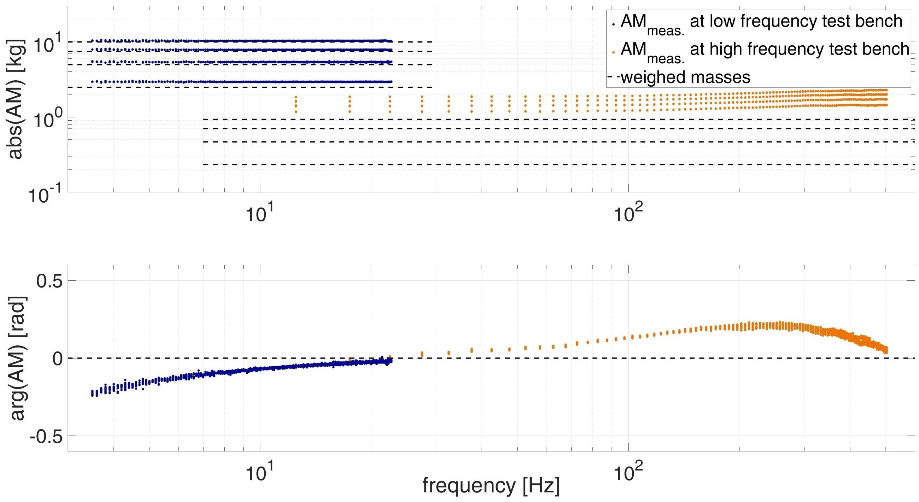
To determine the calibration values, the masses are attached to the load cell of the test bench. The masses can vibrate freely and therefore AM should be a real constant value over the whole frequency range which corresponds to the mass. Figure 5 shows the ideal values of the measured masses with dashed lines. The masses are given in Section 2.5. The values for A M m e a s . are derived from testing. They are marked blue for the low frequency and orange for the high frequency test bench. For each mass configuration studied, three repetitions were performed. The mass configuration and reputations were performed in a random order. Each test is evaluated at 200 different frequencies. All results are plotted in Figure 5.
The deviation of the magnitude of the mass a b s ( A M ) is mainly due to the additional mass m s e n s o r , as it is to be extracted according to Ewins [26]. The phase diagram in Figure 5 shows the phase of AM. According to Equation (3), the AMs angle a r g ( A M ) describes the phase difference between force and acceleration. Ideally, there should be no phase shift between force and acceleration. A phase shift differing from n · π means that there is an imaginary part that is related to damping. A stiffness would lead to a phase shift of π , resulting in a negative real part for AM. The test results show a phase that deviates from zero, which for the low frequency test bench increases from −0.2 rad at 3 Hz to near 0 rad at 23 Hz. For the high frequency test bench it increases from around 0 up to 0.2 rad at 250 Hz and decreases back to near 0 rad at 500 Hz. The negative phase angle of the low frequency test bench indicates that the force is behind the acceleration signal in the time domain and this is equivalent to the force signal behind the displacement by more than π . Instead, the positive phase angle at the high frequency test bench indicates that the acceleration is behind the force signal. Both deviations indicates that the phase shift is due to a delay in the measuring system.

3.2. Calibration of the Measurement System

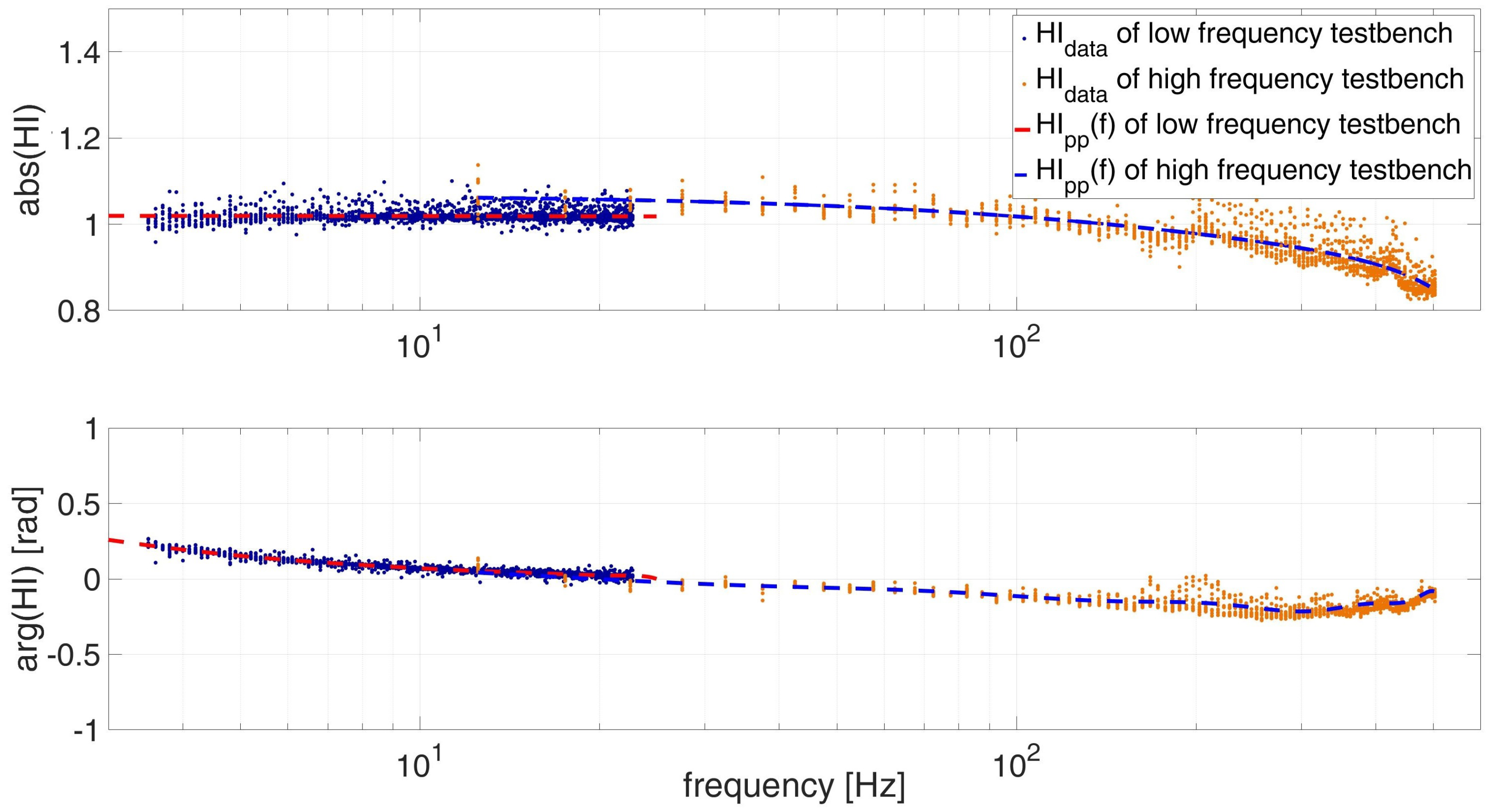
The determination of the measurement systems FRF  H I p p is given by Equation (18). The masses of the sensor at each test bench are derived at Section 2.5. Each weighted real constant mass configuration (Table 1) is divided by the corresponding measured complex value of A M m e a s . ( f ) . The resulting values for the low and high frequency test bench are marked in frequency domain as data points (Figure 6). At each evaluated frequency, 12 data points resulting from four different mass configurations with each three reputations are shown.
The magnitude of a b s ( H I ) for the low frequency test bench is slightly above the ideal magnitude value of one, while a b s ( H I ) for the high frequency test bench is decreasing from a value of 1.05 to 0.85. To determine HI, the mass m s e n s o r has already been subtracted. The phase difference behaves as the inverse of A M m e a s . ( f ) shown in Figure 5. The deviation from the ideal magnitude one and phase difference zero show the necessity to use the calibration function H I p p , as introduced by McConnell [27]. The pure mass cancellation of Ewins [26] is not enough to calculate the deviation from the ideal result for the given test benches, even though both test stands are statically calibrated.
The data points of H I p p scatter around a center value depending on the frequency. A continuous FRF has to be formulated. A polynomial function allows a flexible determination when the behavior is unknown [35]. Using a polynomial function, however, cannot be recommended to extrapolate results at the far ends of the determined data [35]. The polynomial function is determined individually for the magnitude and phase angle, and then combined to the complex function H I p p ( f ) in Euler form. In this way, the HI function can be represented in a shorter notation than if always the higher polynomial degree is used for both magnitude and phase angle. The high amount of data points k theoretically allows the determination of a polynomial of a high degree of k 1 [36]. The data to be described can be expressed by a function of much lower polynomial degree. For this, the residual between the data points H I p p , n and the function H I p p , f i t can be minimized [36].
e = 1 N n = 1 N | H I p p , n ( ω ) H I p p , f i t ( ω ) |
The average residual e can be calculated by Equation (19) for each function H I p p , f i t . Figure 7 shows the average residual over the degree of the polynomial of the argument and the modulus. The average residual is calculated from the summed up difference between each data point and the function, with a given polynomial degree divided by the amount of data points k.
As a compromise between a simple description versus the accuracy of the data, the lowest polynomial degree is chosen, whose relative change of the residual to the next polynomial degree is less than 1% (marked as red circle at Figure 7). The two following functions describe the resulting function H I p p ( f ) for each test bench. The resulting functions are marked as dashed lines in Figure 6 and qualitatively fit the data.
H I p p , f i t , l o w f r e q ( f ) = ( 1.0196 5.7312 · 10 5 · f ) · e x p ( i · ( 0.52767 0.1353 · f + 0.01676 · f 2 0.001087 · f 3 + 3.5122 · 10 5 · f 4 4.4507 · 10 7 · f 5 ) )
H I p p , f i t , h i g h f r e q ( f ) = ( 1.056 3.1385 · 10 4 · f 8.9521 · 10 7 · f 2 + 4.0439 · 10 9 · f 3 5.3453 · 10 12 · f 4 ) · e x p ( i · ( 0.02695 0.0021295 · f + 9.3418 · 10 6 · f 2 2.2897 · 10 8 · f 3 + 2.4072 · 10 11 · f 4 ) )

3.3. The Dynamic Response of the Masses

To check the calibrated measurement by mass cancellation and the determined function, H I p p ( f ) is reapplied to the already measured masses under vibration. A M t e s t o b j . ( f ) is calculated by Equation (13), the results are shown in Figure 8. As in Figure 5 the ideal values of the measured masses (Section 2.5) are shown with dashed lines and the data points of each test bench are marked blue and orange.
The deviations from the ideal expected behavior of a real mass in Figure 8 are much smaller than the uncorrected ones shown in Figure 5. The better representation of the magnitude of AM is mainly due to the elimination of the mass m s e n s o r (Equation (13)). The smaller deviation from the ideal behavior of the phase of AM is due to the determination of the measurement systems FRF H I p p (Equation (13)). The uniform reduction in the deviations shows that the correction using a frequency-dependent function HI is suitable for achieving the desired results.
In order to quantitatively evaluate the improvements of the measurement results by the presented calibration, the deviation of the test results are to be determined. Furthermore, the deviation shall be compared to the procedures of Ewins [26] and Dong et al. [25]. The deviation determined in each case is given by the difference of AM and the weighed masses m i (Section 2.5) by Equation (22). Since the masses vary, the relative deviation is determined by dividing the absolute deviation by the corresponding mass resulting in Equation (23).
e A M , a b s = 1 N n = 1 N | A M n ( ω ) m i |
e A M , r e l = 1 N n = 1 N | A M n ( ω ) m i | m i
The deviation of the results is examined for the following approaches: static calibration only, mass cancellation by Ewins only, mass cancellation and measurement systems FRF  H I p p and mass cancellation by Dong et al. and measurement systems FRF H I p p , f i t and mass cancellation determined over multiple masses as presented here in this publication. For the determination of the average deviation e A M by the static calibration A M n = A M m e a s u r e d is used and or the mass cancellation only, A M n = A M m e a s u r e d m s e n s o r . For the mass cancellation and measurement systems FRF as used by Dong A M t e s t o b j . from Equation (18) are used, the function H I p p , f i t is calculated only by the mass of the sensor and adapter. For comparison, the procedure addressed in this publication is listed with the measurement of different added masses (Table 1). The resulting absolute and relative average deviation e A M by by Equation (22) and by Equation (23) for each of the four approaches is shown in Table 2.
By only statically calibrated sensors without consideration the influence of fixtures and measuring devices of the test bench a clear deviation of test results can be seen. The deviation in this case is particularly due to the mass of the sensors and adapters and the size thus also corresponds roughly to the mass m s e n s o r (Table 1). The deviation on the low frequency test bench deviates from the mass m s e n s o r , l o w f r e q , this indicates a uniform deviation of the determined AM, which then leads to a deviation resulting over all measured masses. Since the tested masses on the high frequency test bench are lower than the mass of the adapter and the sensors, it results in a very high relative deviation of the measurement results of over 250 %. For this reason, the deviation due to mass cancellation on the high frequency test rig decreases a lot. The approach of Dong et al. [25] considers influences of measuring devices and of fixtures exceeding their mass, decreasing the deviation further. Especially the deviation at the low frequency can be decreased by this method by a factor of five. The determination of H I p p , f i t over several masses has the advantage that it is determined over a larger range of loads. Thus, nonlinear effects, especially in the lower load range, are not extrapolated to results in the higher load range. Furthermore, the measurement noise relative to the measured force has less influence on the determination of H I p p . The deviation can be more than halved for both test benches. The resulting deviation is 0.0433 kg for the low frequency test bench and 0.0237 kg for the high frequency test bench.
Since the values are derived from the related test results themselves, these only give an indication of the possibilities of the method. In the following subsection, the use of the specific correlation is applied to two compliant elements.

3.4. Evaluation of the Dynamic Response of the Compliant Elements

The evaluation of the possibilities of the adapted approach (Section 2.2 and Section 2.3) is shown in this section for the compliant elements A and B (Figure 4). The measured force, analytically given by Equation (1) results from the stiffness, damping, and mass properties of the element. The resulting force is dependent on displacement, velocity and acceleration, which are derivatives of each other. Since AM, MI and AS are given by force over acceleration, velocity and displacement (see Equation (3)), they are inverse derivatives as well (see Equation (5)). Figure 9 shows the test results of the compliant element A (Figure 4) in form of AM, MI and AS, as well as the phase of AS. All plots have their advantage in analyzing specific parts of the test objects behavior. The measured data points for A M m e a s . , M I m e a s . and A S m e a s . are marked as dots and the calibrated ones A M t e s t o b j . , A M t e s t o b j . and A S t e s t o b j . are marked as asterisks.
From the nearly constant part of a b s ( A S ) in Figure 9 in front of the first natural frequency results that the behavior of compliant element A is dominated by its stiffness. A phase angle of AS near zero or n · π also shows a stiffness-dominated behavior. The natural frequency can be determined at the phase change and the point of least necessary force to excite the element, which therefore is also described by the low point of AM, MI and AS. With increasing frequency, the acceleration increases (Equation (2)), and with it the force component of mass multiplied by acceleration. For AS and MI in Figure 9 this can be seen as an increase over frequency, especially above the natural frequency. At high frequencies the force component of the mass dominates this behavior; therefore, in the plots of AM, they converge to an asymptote, which corresponds to the real vibrating mass. From the plot MI, the damping behavior can be derived, since at the natural frequency ( ω 0 = k / m ) the resulting force from mass and stiffness cancel each other and only the damping force remains (Equation (1)).
When determining the stiffness in the lower frequency range, the influence of calibration by mass cancellation is negligible. In addition, the influence of the H I p p function is less than 2% for the low frequency test bench (Section 3.2). The value of the deepest point of MI is located at the natural frequency and is smaller for the calibrated measurement. The resulting force from the non-calibrated, as well as from the calibrated measurement, dissolve in both cases with the force resulting from stiffness. The remaining damping force is at a higher frequency, respectively higher velocity, which is why MI is lower.
In all frequency ranges, except very low frequencies and at the natural frequency, the mass cancellation introduced by Ewins [26] and the measurement systems FRF  H I p p by McConnell [27] have a clear influence on the results. Noticeable in all diagrams is the deviation of the natural frequency between the non-calibrated measurement at approximately 80 Hz and the calibrated measurement at approximately 190 Hz. In the calibrated measurement, the mass m s e n s o r , h i g h f r e q = 1.133 kg is subtracted, which directly affects the natural frequency. In addition, the asymptote, approached by AM at high frequencies, differs between the non-calibrated and calibrated measurement by the mass m s e n s o r .
The phase angle of AM, MI and AS is also crucial for vibration analysis. A phase angle of a r g ( A S ) = 0 shows that force and displacement are in phase and thus describe an ideal spring. A phase angle of a r g ( M I ) = 0 is equivalent to a r g ( A S ) = π / 2 and describes that force and velocity are in phase and therefore an ideal viscous damper. A phase angle of a r g ( A M ) = 0 is equivalent to a r g ( A S ) = π and describes an ideal mass.
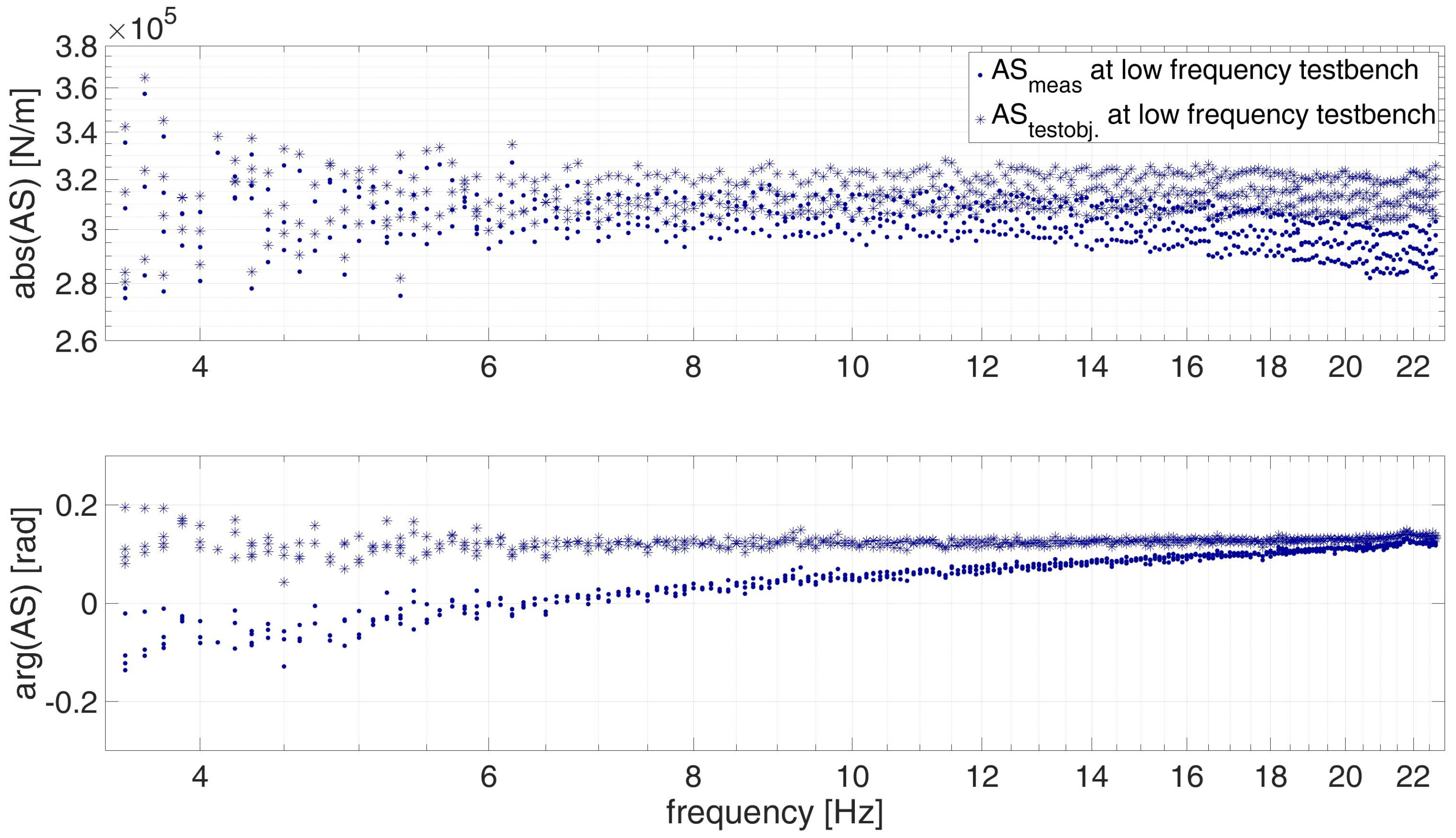
Figure 10 shows AS of the low frequency test bench in detail. As previously mentioned, in the low frequency range the influence of mass is negligible. The correction by H I p p ( f ) on a r g ( A S ) is small; however, H I p p ( f ) has a decisive influence on the phase angle a r g ( A S ) . The uncorrected phase a r g ( A S m e a s . ) changes from negative values to positive values with increasing frequency. The dynamic calibrated phase a r g ( A S t e s t o b j . ) stays nearly constant over frequency at around 0.1 rad.
The calibrated measurement results are more realistic, since the non-calibrated ones cannot be described mechanically with a positive damping coefficient. A negative phase angle of AS means that the force is behind the displacement signal in time domain. This correlation can not be represented by the mechanical equation of motion (Equation (1)) with a sinusoidal displacement (Equation (2)) having a positive damping coefficient c. The real part of AS is described by the stiffness and mass. The imaginary part is only described by the damping and is therefore the only part to change the phase angle from 0 and correspondingly n · π . It is clear that the negative phase shift is due to a delay in the measuring system, and not given by a negative damping coefficient.
Figure 11 shows the calibrated frequency response functions AM, MI, AS and its phase for two compliant elements: one with double rubber buffer in each stack (Figure 4a) and the other one with a single rubber buffer in each stack (Figure 4b). Halving the stacks of the rubber buffer doubles the stiffness from compliant element A to B. This can be clearly seen in the low frequency range of A S m e a s . and increases as well the natural frequency.
Both compliant elements show a stiffness dominated behavior. The stiffness of element B with 540 N / m m is not twice as large as that of element A with 300 N/mm. This is most likely due to the nonlinear behavior of the rubber buffers themselves, since the single stacks are compressed twice as much as the double stacks at the same amplitude. The phase difference of both compliant elements are almost equal in front of the first natural frequency.
The calibrated measurement of compliant element A has its natural frequency at approximately 190 Hz (Figure 11 blue dots) and compliant element B at 240 Hz (Figure 11 black dots). For element A it is shown that the non-calibrated measurement provides a natural frequency of about 80 Hz (Figure 9) and the non-calibrated measurement of the compliant element B determines a natural frequency of 110 Hz. The relative difference between the non-calibrated to the calibrated measurement for the given elements is larger than the difference between the two elements themselves. This again shows the high sensitivity of the test results by mass cancellation and measurement systems FRF  H I p p .

3.5. Findings from the Performed Dynamic Calibration

The compliant structures presented in literature (Section 1) have been investigated in specific test ranges. For the use of AIEs as interface elements in vibration testing further application requirements must be fulfilled. An increase in the investigated force, displacement and frequency range of the test object leads to the necessity to calibrate the test benches in the entire test range. Investigations of the FRFs AS, MI and AM show deviations from the ideal behavior of a freely vibration mass. Calibration quantities can be calculated by the known systematic deviation from the ideal behavior.
The investigations on the vibrating mass and the compliant elements have shown the influence and resulting possibilities on the measurement results by mass cancellation and measurement systems FRF  H I p p . To make sure that these influences do not only apply to one specific sensor and measuring system, the investigation was carried out on the two clearly different systems presented. This led to different calibration values for H I p p and m s e n s o r . Consequently, the calibration quantities must be determined for each configuration. Even if the test setup is not changed, “frequent checks on the calibration factors are strongly recommended” [26].
The measurement systems FRF  H I p p is determined only for the test data of the freely vibration mass, and is limited at its ends. Furthermore, the function H I p p ( f ) depends on the data accuracy from which it is created. The residual should be determined from using sufficient data and the accuracy should be evaluated. The measurement systems FRF H I p p and its values are determined over frequency. Non-systematic errors and non-linearly dependent correlations cannot be described or compensated. For example, non-linear friction effects of the test bench between sensor positions cannot be represented. Such effects should only be attributed to the test element. The test results of four different masses and two different compliant elements on both test rigs showed almost linear effects in the lower and medium frequency range. In high frequency ranges above 300 Hz deviations of the vibrating mass could be attributed to non linearity.
Ewins [26] already mentioned, with regards to the calibration by mass cancellation, that “a calibration procedure of this type has the distinct advantage that it is very easy to perform, and that it can be carried out in situ with all the measurement equipment” [26]. Further, the additions by the measurement systems FRF  H I p p by McConnell [27] can be performed directly with all the measurement equipment. For the calibration, the test object must be replaced by a freely vibrating mass and the two relevant quantities are then measured. The measurement of the test object can be performed immediately. The calibration can be calculated afterwards and later applied to the measurement results of the test object. Even if the evaluation of the test results becomes more complicated due to the determination of the calibration values, it is still easy to implement in testing.

4. Conclusions

The presented approach is suitable for the investigation of compliant interface elements over a wide range of test conditions. The approach is shown representatively for two configurations of compliant elements. Plots of the AS, MI and AM and the associated phase are necessary to clearly identify the dynamic characteristics over the wide frequency range. These plots are also suitable to clearly recognize measurement errors and influences of fixtures. By plotting AM, MI or AS, it is possible to identify behaviors that deviates from the ideal case and thus highlight the need for calibration. If the dynamic behavior of a reference sample, such as when the free vibrating mass is known, systematic errors can be calculated. The systematic errors can be characterized by the mass cancellation by Ewins et al. [26] and the frequency dependent measurement systems FRF by McConnell et al. [27].
For the investigation of compliant elements on the shown test benches a dynamic calibration as recommended by Dong et al. [25] is useful. The mass cancellation as introduced by Ewins et al. [26] had a decisive influence on the results of the determined mass of the element itself, and therefore also on its natural frequency. The measurement systems FRF  H I p p introduced by McConnel et al. [27], due to its complex notation, has the ability to adjust the magnitude and phase angle of the measurement results.
For the two representative test benches, the calibration presented had a meaningful impact on the test results. When measuring the freely vibrating masses on the low frequency test bench, the deviation could be reduced from 0.625 kg (12%) to 0.043 kg (0.75%); on the high frequency test bench, reduced from 1.158 kg (252%) to 0.024 kg (4.2%). The values of the different calibrations have to be determined for each test bench and each sensor configuration. The effects are different depending on their characteristics.
The measurements have been performed on two non-adjustable compliant elements. This was implemented so that inaccuracies in the setting of the adjustment of the AIEs do not affect the test results, especially when switching between the test benches. Deviations between the non-calibrated and calibrated test results are dominated by measurement effects, and not by the adjustment of the elements. Two different configurations are represented by two configurations of compliant elements. A differentiation of properties is shown. Further testing of AIEs with more adjustment settings would follow the same approach.
The investigated experiments were carried out on relatively high-quality test benches (details in [8]) and with recently calibrated measuring equipment. Nevertheless, a deviation from the ideal behavior of a freely vibrating mass can be recorded. It can only be recommended to examine a freely vibrating mass during vibration testing. If there are any deviations from the ideal expected behavior, a dynamic calibration should be performed. For dynamic calibration, the usefulness of the approach by Dong et al. [25] has been confirmed. If larger forces are to be measured on the test bench, it is recommended to use an additional mass as in this publication.
In summary, it can be stated that the procedure for the calibration of biodynamic responses intended for testing of hand–arm models can be transferred with necessary modifications to the dynamic calibration of machine elements such as AIEs. Dynamic calibration can have a decisive influence on the measurement results and should always be performed for vibration testing of compliant elements.

Author Contributions

All the authors contributed to the development of the approach in their respective fields. Conceptualization, E.H., A.L., S.M. and D.K.; methodology, E.H., A.L., S.M. and D.K.; validation, E.H. and A.L.; formal analysis, E.H. and A.L.; investigation, E.H. and A.L.; resources, S.M. and D.K.; data curation, E.H. and A.L.; writing, E.H.; visualization, E.H.; supervision, S.M. and D.K.; project administration, E.H., A.L., S.M. and D.K. All authors have read and agreed to the published version of the manuscript.

Funding

This research was funded by by DFG—Deutsche Forschungsgemeinschaft (Project AIProVE—number 399922375). The statements and information in this contribution do not necessarily represent the opinion of DFG.

Institutional Review Board Statement

Not applicable.

Informed Consent Statement

Not applicable.

Data Availability Statement

Not applicable.

Conflicts of Interest

The authors declare no conflict of interest.

Abbreviations

The following abbreviations are used in this manuscript:
absabsolute value or magnitude in polar coordinate system
ACaccelerance
AIEadjustable impedance element
AMapparent mass
argargument in polar coordinate system
ASapparent stiffness
FRFfrequency response function
MImechanical impedance
MOmobility
REreceptance

References

  1. Heyden, E.; Lindenmann, A.; Oltmann, J.; Bruchmueller, T.; Krause, D.; Matthiesen, S. Adjustable Impedance Elements for Testing and Validation of System Components. In Symposium Lightweight Design in Product Development; Ermanni, P., Meboldt, M., Wartzack, S., Krause, D., Zogg, M., Eds.; CMASLab, ETH: Zurich, Switzerland, 2018; pp. 44–46. [Google Scholar]
  2. Lalanne, C. Sinusoidal Vibration, 3rd ed.; John Wiley & Sons, Ltd.: Chichester, UK, 2014. [Google Scholar] [CrossRef]
  3. Moldenhauer, B.; Allen, M.; DeLima, W.J.; Dodgen, E. Using Hybrid Modal Substructuring with a Complex Transmission Simulator to Model an Electrodynamic Shaker. In Dynamic Substructures; Linderholt, A., Allen, M.S., Mayes, R.L., Rixen, D., Eds.; Conference Proceedings of the Society for Experimental Mechanics Series; Springer International Publishing: Cham, Switzerland, 2020; Volume 4, pp. 23–34. [Google Scholar] [CrossRef]
  4. Karlicek, A.C.; Dilworth, B.J.; McDaniel, J.G. System Characterization and Design Using Mechanical Impedance Representations. In Special Topics in Structural Dynamics & Experimental Techniques; Epp, D.S., Ed.; Conference Proceedings of the Society for Experimental Mechanics Series; Springer International Publishing: Cham, Switzerland, 2021; Volume 5, pp. 121–128. [Google Scholar] [CrossRef]
  5. Kim, J.Y.; Jeong, W.B.; Lee, S.B.; Lee, B.H. An Experimental Approach for Structural Dynamic Modification of Fixture in Vibration Test Control. JSME Int. J. Ser. C 2001, 44, 334–340. [Google Scholar] [CrossRef] [Green Version]
  6. Rivin, E. Design Techniques for Reducing Structural Deformations (Stiffness Enhancement Techniques). In Handbook on Stiffness & Damping in Mechanical Design; Rivin, E.I., Ed.; ASME: New York, NY, USA, 2010; pp. 371–453. [Google Scholar] [CrossRef]
  7. Heyden, E.; Hartwich, T.S.; Schwenke, J.; Krause, D. Transferability of Boundary Conditions in Testing and Validation of Lightweight Structures. In Proceedings of the 30th Symposium Design for X (DFX 2019), Jesteburg, Germany, 18–19 September 2019; pp. 85–96. [Google Scholar] [CrossRef]
  8. Lindenmann, A.; Heyden, E.; Matthiesen, S.; Krause, D. Adjustable Impedance Elements for Testing and Validation of Aircraft Components and Hand-Held Power Tools. In Stuttgarter Symposium für Produktentwicklung SSP 2019; Binz, H., Bertsche, B., Bauer, W., Riedel, O., Spath, D., Roth, D., Eds.; Fraunhofer-Institut für Arbeitswirtschaft und Organisation IAO: Stuttgart, Germany, 2019; pp. 63–72. [Google Scholar]
  9. Vanderborght, B.; Albu-Schaeffer, A.; Bicchi, A.; Burdet, E.; Caldwell, D.G.; Carloni, R.; Catalano, M.; Eiberger, O.; Friedl, W.; Ganesh, G.; et al. Variable impedance actuators: A review. Robot. Auton. Syst. 2013, 61, 1601–1614. [Google Scholar] [CrossRef] [Green Version]
  10. van Ham, R.; Sugar, T.; Vanderborght, B.; Hollander, K.; Lefeber, D. Compliant actuator designs. IEEE Robot. Autom. Mag. 2009, 16, 81–94. [Google Scholar] [CrossRef]
  11. Tagliamonte, N.L.; Sergi, F.; Accoto, D.; Carpino, G.; Guglielmelli, E. Double actuation architectures for rendering variable impedance in compliant robots: A review. Mechatronics 2012, 22, 1187–1203. [Google Scholar] [CrossRef]
  12. Petit, F.; Friedl, W.; Höppner, H.; Grebenstein, M. Analysis and Synthesis of the Bidirectional Antagonistic Variable Stiffness Mechanism. IEEE/ASME Trans. Mechatron. 2015, 20, 684–695. [Google Scholar] [CrossRef]
  13. Stucheli, M.; Foehr, A.; Meboldt, M. Work density analysis of adjustable stiffness mechanisms. In Proceedings of the 2016 IEEE International Conference on Robotics and Automation (ICRA), Stockholm, Sweden, 16–21 May 2016; pp. 648–654. [Google Scholar] [CrossRef]
  14. Awad, M.I.; Gan, D.; Cempini, M.; Cortese, M.; Vitiello, N.; Dias, J.; Dario, P.; Seneviratne, L. Modeling, design & characterization of a novel Passive Variable Stiffness Joint (pVSJ). In Proceedings of the 2016 IEEE/RSJ International Conference on Intelligent Robots and Systems (IROS), Daejeon, Korea, 9–14 October 2016; pp. 323–329. [Google Scholar] [CrossRef]
  15. Vuong, N.D.; Li, R.; Chew, C.M.; Jafari, A.; Polden, J. A novel variable stiffness mechanism with linear spring characteristic for machining operations. Robotica 2017, 35, 1627–1637. [Google Scholar] [CrossRef]
  16. Hošovský, A.; Pite’, J.; Židek, K.; Tóthová, M.; Sárosi, J.; Cveticanin, L. Dynamic characterization and simulation of two-link soft robot arm with pneumatic muscles. Mech. Mach. Theory 2016, 103, 98–116. [Google Scholar] [CrossRef]
  17. Li, Z.Q.; Xu, Y.L.; Zhou, L.M. Adjustable fluid damper with SMA actuators. Smart Mater. Struct. 2006, 15, 1483–1492. [Google Scholar] [CrossRef]
  18. Deng, H.; Deng, J.; Yue, R.; Han, G.; Zhang, J.; Ma, M.; Zhong, X. Design and verification of a seat suspension with variable stiffness and damping. Smart Mater. Struct. 2019, 28, 065015. [Google Scholar] [CrossRef]
  19. Xing, Z.; Yu, M.; Sun, S.; Fu, J.; Li, W. A hybrid magnetorheological elastomer-fluid (MRE-F) isolation mount: Development and experimental validation. Smart Mater. Struct. 2016, 25, 015026. [Google Scholar] [CrossRef]
  20. Sun, S.; Deng, H.; Du, H.; Li, W.; Yang, J.; Liu, G.; Alici, G.; Yan, T. A Compact Variable Stiffness and Damping Shock Absorber for Vehicle Suspension. IEEE/ASME Trans. Mechatron. 2015, 20, 2621–2629. [Google Scholar] [CrossRef]
  21. Sun, S.; Tang, X.; Li, W.; Du, H. Advanced vehicle suspension with variable stiffness and damping MR damper. In Proceedings of the 2017 IEEE International Conference on Mechatronics (ICM), Churchill, VIC, Australia, 13–15 February 2017; pp. 444–448. [Google Scholar] [CrossRef]
  22. Wu, T.H.; Lan, C.C. A wide-range variable stiffness mechanism for semi-active vibration systems. J. Sound Vib. 2016, 363, 18–32. [Google Scholar] [CrossRef]
  23. Meng, K.; Sun, Y.; Pu, H.; Luo, J.; Yuan, S.; Zhao, J.; Xie, S.; Peng, Y. Development of Vibration Isolator With Controllable Stiffness Using Permanent Magnets and Coils. J. Vib. Acoust. 2019, 141, 954. [Google Scholar] [CrossRef]
  24. Jujjavarapu, S.S.; Memar, A.H.; Karami, M.A.; Esfahani, E.T. Variable Stiffness Mechanism for Suppressing Unintended Forces in Physical Human–Robot Interaction. J. Mech. Robot. 2019, 11, 1–7. [Google Scholar] [CrossRef] [Green Version]
  25. Dong, R.G.; Welcome, D.E.; McDowell, T.W.; Wu, J.Z. Measurement of biodynamic response of human hand–arm system. J. Sound Vib. 2006, 294, 807–827. [Google Scholar] [CrossRef]
  26. Ewins, D.J. Modal Testing: Theory and Practice, 4th ed.; Mechanical engineering research studies; Research Studies Pr: Taunton, UK, 1989; Volume 2. [Google Scholar]
  27. McConnell, K.G. Vibration Testing: Theory and Practice; Wiley: New York, NY, USA, 1995. [Google Scholar]
  28. International Organization for Standardization. General Requirements for the Competance of Testing and Calibration Laboratories (ISO/IEC 17025:2017). 03/2018. Available online: https://www.iso.org/standard/66912.html (accessed on 25 July 2021).
  29. Silva, J.M.M.; Maia, N.M.M.; Ribeiro, A.M.R. Cancelation of Mass-Loading Effects of Transducers and Evaluation of Unmeasured Frequency Response Functions. J. Sound Vib. 2000, 236, 761–779. [Google Scholar] [CrossRef]
  30. Silva, J.M.M.; Maia, N.M.M.; Ribeiro, A.M.R. Some Applications of Coupling/Uncoupling Techniques in Structural Dynamics: Part 1: Solving the Mass Cancellation Problem. In Proceedings of the SPIE—The International Society for Optical Engineering, Orlando, FL, USA, 21–22 April 1997; pp. 1431–1439. [Google Scholar]
  31. Maia, N.M.M.; Silva, J.M.M.; Ribeiro, A.M.R. Some Applications of Coupling/Uncoupling Techniques in Structural Dynamics: Part 2: Generation of the Whole FRF Matrix from Measurements on a Single Column-The Mass Uncoupling Method (MUM). In Proceedings of the SPIE— The International Society for Optical Engineering, Orlando, FL, USA, 21–22 April 1997; pp. 1440–1452. [Google Scholar]
  32. Laukotka, F.; Hartwich, T.S.; Hauschild, J.; Heyden, E.; Schmidt, J.; Schwenke, J.; Wegner, M.; Wortmann, N.; Krause, D. Entwicklung und Anwendung von Sonderprüfständen. In Produktentwicklung und Konstruktionstechnik; Krause, D., Hartwich, T.S., Rennpferdt, C., Eds.; Produktentwicklung und Konstruktionstechnik; Springer: Heidelberg, Germany, 2020; Volume 19, pp. 177–205. [Google Scholar] [CrossRef]
  33. Brandt, A. Noise and Vibration Analysis: Signal Analysis and Experimental Procedures; John Wiley and Sons Ltd.: Chichester, UK, 2011. [Google Scholar] [CrossRef]
  34. Lang, G.F.; Snyder, D. Understanding the Physics of Electrodynamic Shaker Performance. In Sound and Vibration—Dynamic Testing Reference Issue; Data Physics Corporation: San Jose, CAM, USA, 2001; pp. 24–35. [Google Scholar]
  35. Stone, C.J.; Koo, C.Y. Additive Splines in Statistics. Proc. Am. Stat. Assoc. ASA 1985, 45, 48. [Google Scholar]
  36. Harrell, F.E. Regression Modeling Strategies: With Applications to Linear Models, Logistic and Ordinal Regression, and Survival Analysis; Springer International Publishing: Cham, Switzerland, 2015. [Google Scholar] [CrossRef]
Figure 1. (a) mechanical model of a mass-damper-spring system; (b) mass separated into m s e n s o r and m t e s t o b j . .
Applsci 11 09604 g001
Figure 2. (a) Hydraulic test bench for low frequencies adapted from [32]; (b) electrodynamic test bench for high frequencies.
Applsci 11 09604 g002
Figure 3. Test setup for the compliant element at: (a) low frequency; (b) high frequency test bench.
Applsci 11 09604 g003
Figure 4. (a) Compliant element A with two rubber buffers aligned; (b) compliant element B with one rubber buffer aligned; (c) size of rubber buffer.
Applsci 11 09604 g004
Figure 5. Apparent mass A M m e a s . of freely vibration masses over frequency.
Applsci 11 09604 g005
Figure 6. Measurement systems FRF H I p p over frequency of both test benches.
Applsci 11 09604 g006
Figure 7. Average residual e (Equation (19)) of H I p p ( f ) over degree of fitting polynoma for the low frequency (a) and high frequency (b) test bench. The red circle marks the polynomial degree whose relative change of the residual is less than 1%.
Applsci 11 09604 g007
Figure 8. Calibrated apparent mass A M t e s t o b j . of freely vibrating masses over frequency.
Applsci 11 09604 g008
Figure 9. FRFs AM, MI, AS and its phase directly measured and the calibrated FRFs of the compliant element A over frequency.
Applsci 11 09604 g009
Figure 10. Apparent Stiffness directly measured A S m e a s . and calibrated A S t e s t o b j . of the compliant element A at the low frequency test bench.
Applsci 11 09604 g010
Figure 11. Calibrated FRFs AM, MI, AS and its phase of the compliant elements A and B with double and single rubber buffer in each stack over frequency.
Applsci 11 09604 g011
Table 1. Added masses m i at low and high frequency test bench.
m sensor m 1 m 2 m 3 m 4
low freq. test bench0.863 kg2.482 kg4.965 kg7.448 kg9.9316 kg
high freq. test bench1.133 kg0.234 kg0.467 kg0.7011 kg0.9315 kg
Table 2. Comparison of average deviation e A M by Equation (22) for static calibration, mass cancellation by Ewins [26], H I p p , f i t ( m 0 ) by Dong et al. [25], H I p p , f i t ( m i ) over different added masses.
Average Deviation e AM , abs ( e AM , rel )Low Freq. Test BenchHigh Freq. Test Bench
static calibration0.6252 kg (12.0 %)1.1583 kg (252.6 %)
mass cancellation by Ewins [26]0.4567 kg (8.50 %)0.1125 kg (18.23 %)
H I p p , f i t ( m 0 ) by Dong et al. [25]0.0982 kg (1.68 %)0.0628 kg (10.46 %)
H I p p , f i t ( m i ) over added masses0.0433 kg (0.74 %)0.0237 kg (4.21 %)
Publisher’s Note: MDPI stays neutral with regard to jurisdictional claims in published maps and institutional affiliations.