Abstract
Dynamic behavior modeling and parameter optimization of the spray boom based on multi-body vibration were developed to study the influence of the boom sprayer’s motion in a complex working environment on the dynamic behavior of the spray boom. First, a geometric continuous model of spray boom vibration was established considering the influence of the boom sprayer body and boom suspension. Then, the dynamic behavior of the spray boom under step excitation was studied on a SWAN3WP-500 self-propelled boom spray experimental platform. The time-domain response of spray boom movement was characterized using a multi-channel dynamic test system, and the simulation results of the geometric continuous model were verified. The correlation coefficient between the simulated and experimental results is 0.917, and the maximum relative error is 12.16%. Finally, the effects of boom sprayer speed, spray boom length, and spray boom cross-section shape on spray boom vibration were analyzed through the geometric continuous model. (1) The amplitude and period of vibration at the extremity of the spray boom gradually decline with a rise in boom sprayer speed. (2) The amplitude and period of vibration at the extremity of the spray boom gradually increase when the unilateral spray boom is shorter than 5 m but slowly decrease when it is longer than 5 m. To avoid excessive static elastic deformation of the spray boom, the length of the unilateral spray boom should be controlled within 6 m. (3) A reasonable cross-sectional shape can improve the spray boom vibration, and the spray boom with a type B cross-section can better inhibit the vertical vibration of the spray boom under the same cross-sectional area.
1. Introduction
The proportion of small- and medium-sized boom sprayers with spray ranges of 10–14.9 m in China accounts for more than 70% according to statistics in 2017 [1]. A boom sprayer working in the field is affected by uncertain factors, such as uneven soil, speed change, uneven tire load, and liquid sloshing. Such uncertainty will easily cause harmful movements of the spray boom (e.g., rolling and yawing) and thereby induce a random change of nozzle height from the ground, seriously affecting the spray distribution form and leading to chemical fertilizer/pesticide leakage and heavy spray. Due to the irregular movement of the spray boom, the variation coefficient of overall fog distribution fluctuates from 0% to 800% (the ideal droplet deposition is 100%). The rolling and vertical elastic deformation of the spray boom have a great influence, especially at its extremity when its motion amplitude is the largest, the deposition amount maximizes to 760% and minimizes to 0% [2,3,4]. Since the boom sprayer is a complex multi-body system, establishing an accurate motion model of the spray boom is of great significance to explore its vibration control.
Researchers established dynamic models to describe the dynamic behavior of the spray boom when the boom sprayer walked in the field. Herman derived the motion of the spray boom through a strongly coupled nonlinear time-varying differential equation, but the calculation target was cumbersome, and the results were inconsistent [5]. Subsequently, Herman proposed the modeling technology of a linear time-invariant non-gyro rigid multi-body system with tree structure. The motion equation of the spray boom was analytically derived on basis of the Roberson–Wittenburg method, but its versatility was lowered by the requirement of complex computer analysis and derivation program [6,7]. Jan derived motion equations of the spray boom through the finite element method and discrete element method separately [8]. With the first method, when the stiffness matrix of the flexible body was derived, consideration was given only to the bending caused by bending moment, but not to the tension or torsion of the spray boom [8]. With the second method, the mass distribution of the spray boom was completed by the shape function, and the mass, damping, and stiffness matrices that depended on the shape function were acquired, which decreased the modeling accuracy [8]. Later, Jan established a linear flexible multi-body model of the spray boom by a discrete element method, but this model considered the boom sprayer body and boom suspension as rigid bodies, which seriously reduced the modeling accuracy [9,10]. Qiu studied the motion modeling of a spray boom in the height difference between the left and right tire as the system input. The regression sliding average model (ARMAX) was used to obtain the incentive response model of the front and rear wheels, and then through convolution, the excitation response to the front and rear wheels is synthesized into the response model of spray boom. However, the real input of the boom sprayer is the vertical displacement of the tire [11]. Wu built a suspension-boom model with spring dampers, but the vibration impact of the sprayer body was not considered during modeling [12]. He established a finite element model of the spray boom based on the ANSYS platform and performed a numerical mode analysis. The suspension-spray boom model was established in ADAMS platform based on the established model and modal information, and the elastic deformation at the extremity of the spray boom were analyzed. However, the finite element model established on the platform of ANSYS and ADAMS does not consider the flexibility relationship between components [13]. In this study, based on the Euler–Bernoulli beam theory, the boom sprayer body and boom suspension are regarded as equivalent to the spring damping system, and the influence of the flexible boom sprayer body and boom suspension on the elastic vibration of the spray boom is fully considered. Then, a geometric continuous model of spray boom vibration based on multi-body vibration is established and compared with the experimental results.
2. Materials and Methods
2.1. Vibration Model of Spray Boom
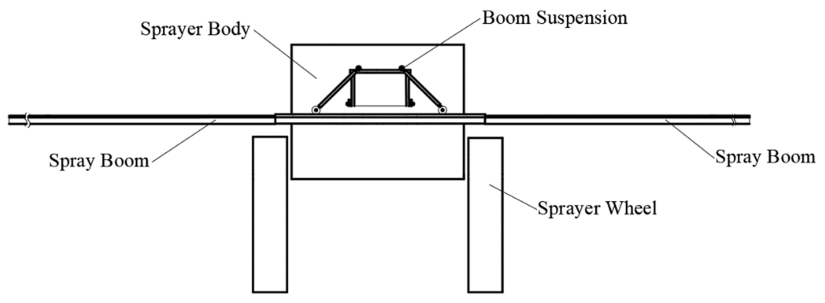
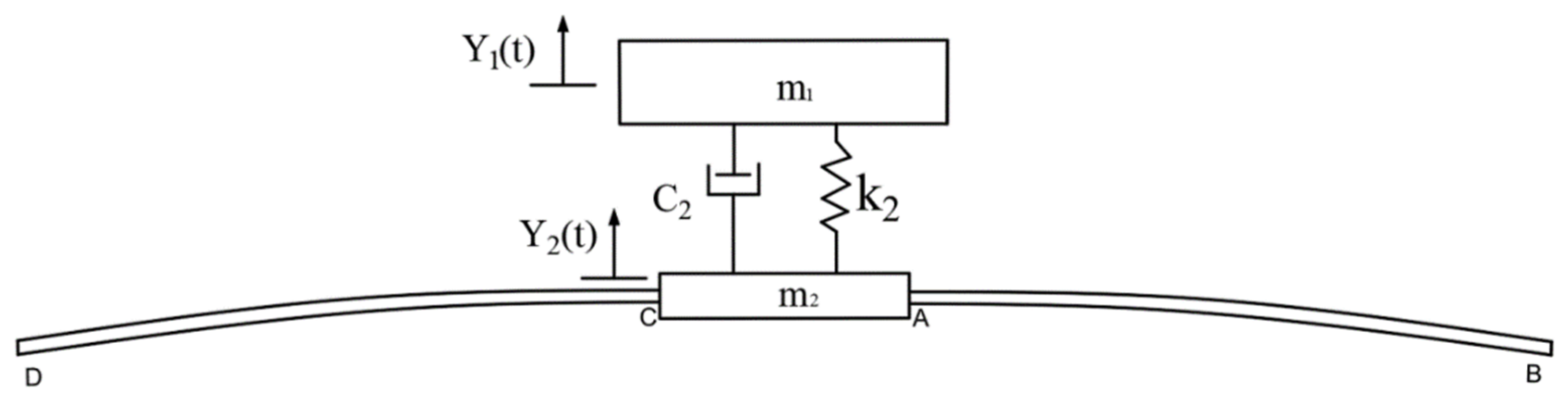
The spray boom is connected by trapezoidal suspension to the boom-lifting mechanism, which is fixed on the body of the boom sprayer. The body is rigidly connected to an inflatable tire through the vertical shaft and the bevel gear. There is no suspension system. The schematic diagram is shown in Figure 1. When the boom sprayer encounters obstacles in the field, it is equivalent to a step excitation to the body of the boom sprayer, causing the body to vibrate vertically, and the spray boom attached to the body will produce vertical oscillation and elastic deformation. According to the connection characteristics of the spray boom, the vertical shaft mechanism of the boom sprayer tire, the connecting tire, and the body is equivalent to a spring damping system. The spray boom can be regarded as an elastic long cantilever beam fixed on a flexible foundation linked by two hinge points. As shown in Figure 2.

Figure 1.
Sprayer body and boom assembly.

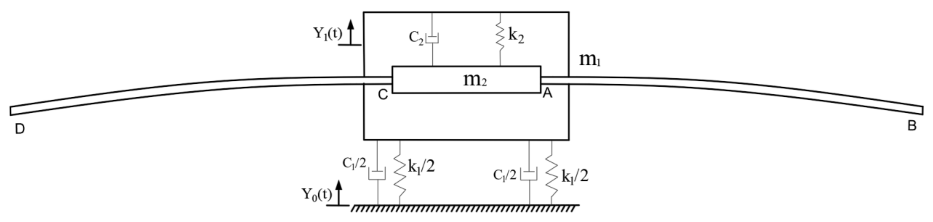
Figure 2.
The multi-body vibration model of the boom sprayer; : stiffness of the boom sprayer tire, ; : tire damping of the boom sprayer, ; : equivalent stiffness of the boom trapezoidal suspension and lifting mechanism, ; : equivalent damping of trapezoidal suspension and lifting mechanism of spray boom, ; : bearing mass of the front bridge of the boom sprayer, : mass of the fixed end of the spray boom, .
The balance position of the boom sprayer at rest is taken as the zero point, and the vertical axis is taken as the positive axis. When the front tire is excited by the step displacement , the response of the load-bearing mass of the front axle of the boom sprayer is .
Let the movement of the vehicle body relative to the ground be . Then, Equation (1) can also be expressed as
If the excitation function and variable are used to replace and , respectively, then Equation (2) is similar to the following equation:
Therefore, the solution of the system excited by external force can be directly applied to the system excited by foundation. In other words, in Equation (3) is used to replace , and the solution of Equation (2) can be determined according to its solution. For an underdamped system subjected to base excitation, the relative displacement is obtained by convolution integral [14]:
where , , and are the damping vibration frequency, natural frequency, and damping ratio of the boom sprayer, respectively, and F(τ) is any external force.
Equation (4) can be simplified as follows:
where is the external force applied to the double front wheels of the boom sprayer, .
Therefore, the response of the front axle of the boom sprayer is:
It is assumed that the front wheels of the boom sprayer encounter a 0.1 × 0.1 m square obstacle during driving. Let the elapsed time be . It can be approximated that a step function starting at and a size of and a step function starting at and a size of for the boom sprayer make the boom sprayer suddenly vibrate upwards first and then downwards. Thus, after the response generated by is subtracted from Equation (6), the response of the front axle when the front wheels encounter a 0.1 × 0.1 m obstacle during driving is:
As shown in Figure 3, when the front axle of the boom sprayer input excitation is , according to Equations (2)–(4), the response of the fixed end of the spray boom can be obtained as:
where , , and are the damping vibration frequency, natural frequency, and damping ratio, respectively, all at the fixed end of the spray boom.

Figure 3.
The vibration model of the spray boom.: equivalent stiffness of the boom trapezoidal suspension and lifting mechanism, ; : equivalent damping of trapezoidal suspension and lifting mechanism of spray boom, ; : bearing mass of the front bridge of the boom sprayer, : mass of the fixed end of the spray boom, .
As for section AB of the spray boom, when the fixed end of the spray boom is excited by , section AB during vibration can be regarded as an elastic long cantilever beam under the excitation of the lateral foundation. For a uniform cross-section spray boom, the differential equation of its free vibration is:
where is the damping constant; is the elastic modulus of the spray boom, ; is its inertia moment, ; is its material density,; and is its cross-sectional area, .
Equation (9) of the bending vibration at section AB is a fourth-order partial differential equation. To obtain the unique solution , the variable separation method is used to separate the solution into the following forms:
where is the main mode shape function, and is the harmonic function of x and t.
Substituting Equation (10) into Equation (9), we have
where is a positive constant. Equation (11) can be expressed as:
where
The solution of Equation (12) is:
where D and F are constants that can be determined according to the initial conditions.
To find the solution of Equation (13), it is assumed that
where and are constants, and Equation (16) is inserted into Equation (13) to obtain
The roots of the equation are
Therefore, the solution of Equation (13) is
Equation (19) can also be expressed as
where , , , and are constants and determined by boundary conditions.
The boundary conditions in which one end of the spray boom is fixed and the other end is free can be expressed as the deflection and rotation angle at the fixed end A (x = 0) of the spray boom being equal to zero:
By introducing condition (21) into Equation (20):
The bending moment and shear force at the extremity of the spray boom () are equal to zero:
Bringing condition (22) into Equation (20) yields:
The condition that Equation (23) has a nonzero solution is
After the above formula is expanded and simplified:
The above equation is divided into . The two parametric equations draw curves separately in the same coordinate system. The intersection of the two equations is the solution of Equation (25), and its first three orders of eigenvalues are as follows:
For each characteristic root , it can be accurately taken as:
The natural frequency of section AB can be calculated by Equation (14), and the natural frequencies of section AB are:
The ratio of coefficients can be determined by substituting each characteristic root into Equation (24):
Therefore, the vibration mode function of section AB is:
The orthogonality verification of Equation (29) is not elaborated here. The vibration solution of section AB under the transverse excitation of foundation is obtained by a vibration mode superposition method. It is assumed that the deflection of section AB is:
where is the generalized coordinate of the system.
The velocity at each point on the spray boom can be expressed as:
The kinetic energy of the system is:
where is the generalized mass of the spray boom.
The bending moment of each section on the spray boom of section AB can be expressed as
Since only the bending potential energy of the system is considered, the potential energy of the system can be expressed as:
where .
The virtual displacement of the unilateral spray boom can be expressed as:
The virtual work done on the virtual displacement of unit length load on the unilateral spray boom is:
The generalized force is:
The kinetic energy, potential energy, and generalized force are substituted into the Lagrange equation:
By simplifying Equation (38), the motion differential equation of the spray boom in generalized coordinates is obtained:
Given the damping of the spray boom and let the th damping ratio be , then Equation (39) is changed to
The inertial force acting on the spray boom when it vibrates with the fixed support end can be expressed as:
Substituting Equation (41) into Equation (37), the generalized force on the spray boom is
By substituting this generalized force into Equation (40), the vibration differential equation of the spray boom with a flexible foundation is
where .
The Laplace transform of Equation (43) is:
Then, the response function between and is:
Since the vibration response of the spray boom does not exceed the first-order mode when it is working, we only calculate the response under the first-order mode. Then, the generalized coordinates of the first order at the extremity of the spray boom are:
Then, the differential dynamics model of the extremity of the spray boom in the first-order mode is
Using the inverse Laplace transform, Equation (47) can be rewritten as [14]:
2.2. Determination of Boom Sprayer Parameters
To verify the correctness of the proposed continuous vibration model of the spray boom based on multi-body vibration, the SWAN3WP-500 self-propelled boom sprayer (Essen Agricultural Machinery Changzhou Co., Ltd., Changzhou, China) was selected as a test model. The mass of this boom sprayer is 1250 kg, and the load-bearing mass of the front axle is 480 kg. The spray width is 12.5 m, and the extension length of the unilateral spray boom from the boom sprayer body is 5 m.
The stiffness of the boom sprayer tire is related to the rim diameter, cross-sectional width, inflation pressure, service years of the tire, and other parameters. So far, a large number of experimental studies provide some valuable experience data and empirical formulas [15,16,17,18]. The tire stiffness empirical formula obtained by the test method of Lines et al. [13] was used here:
where is the tire stiffness,; D and W are the rim diameter and tire section width, respectively; H is the number of used years of the tire; and is the tire inflation pressure, kPa. D and W were directly obtained from the tire model. The service life is one year, and the inflation pressure is 220 kPa. Hence, the tire stiffness is about 585.65.
Tire damping is related to tire deformation, tire inflation pressure, vibration velocity, and excitation frequency [19]. Herein, a nonlinear model of tire damping established by Chen Donghua et al. through a harmonic excitation method [20] is used. The tire damping is about 2682.6.
The equivalent stiffness of the trapezoidal suspension and lifting mechanism of the spray boom is mainly the bending deformation of the connecting rod and the hydraulic oil stiffness of the electric hydraulic cylinder. The equivalent damping of the mechanism is mainly the relative motion of the connecting point at the end of the connecting rod. Many experimental studies provide valuable empirical data and empirical formulas [21,22]. Herein, the suspension and lifting mechanism is simulated by dynamically analyzing the boom suspension performance of the boom sprayer [22]. The and are taken to be 84 and 472.4 , respectively. The related parameters of the boom sprayer are shown in Table 1.

Table 1.
Main parameters of the boom sprayer.
The material of the spray boom is aluminum alloy 6063-T5 that has two cross-section structures (Figure 4). When the spray boom is working, the long side of the cross-section is vertical, and the short side is horizontal. The type A cross-section structure of the spray boom is used in this experiment. Related parameters are shown in Table 2.
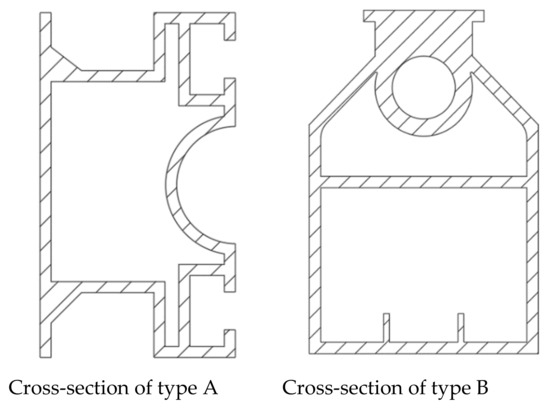
Figure 4.
Cross-sectional structures of the spray boom.
Table 2.
Main parameters of the spray boom.
The damping ratio of the spray boom is determined by a free vibration test [23]. In brief, an acceleration sensor is installed on the extremity of the spray boom, and then a vertical upward pulling force is applied to make the extremity pull up vertically and stay static. Then, the pulling force is removed, and the acceleration data of the extremity are collected. It is calculated as follows:
where is the peak value of the acceleration response of the free vibration of the single-degree-of-freedom system; and are the th and )th peak values, respectively. The mean obtained in the experiment is about 0.12.
2.3. Dynamic Response Simulation of the Spray Boom under Step Excitation
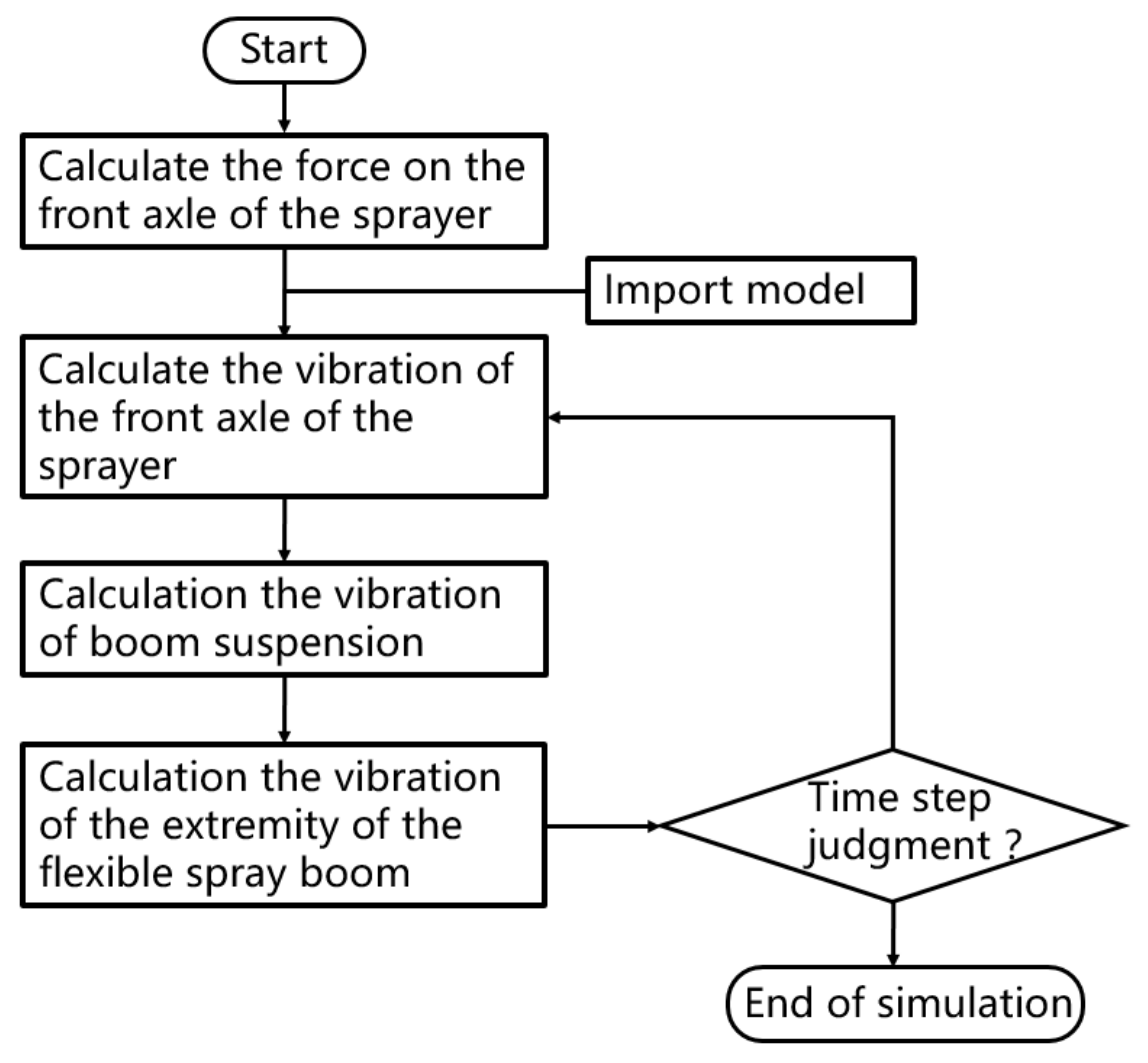
When the boom sprayer passes through an obstacle at a certain speed, it is like being excited by a step. The upward force exerted by the obstacle on the boom sprayer was obtained by simulation on the multi-body dynamics software RecurDyn [24]. The speed of the boom sprayer in the field is about 6 . In RecurDyn, the conditions of passing through 0.1 × 0.1 m obstacles at three vehicle speeds of 4, 6, and 8 were simulated, and the upward force on the front axle of the boom sprayer was about 4800, 5200, and 6320 N. The time for the front wheels to pass the obstacle was about 0.09, 0.06, and 0.045 s, respectively. Then, relevant model parameters were set according to Table 1 and Table 2. The dynamic response simulation of the spray boom is shown in Figure 5. First, the force on the front axle of the boom sprayer was calculated. Then, the dynamic model was imported. Third, the vibration of the front axle was calculated. Fourth, boom suspension vibration was calculated. Fifth, vibration of the extremity was calculated. Sixth, whether the number of iterations was reached was judged; if not, the simulation was continued; if yes, the simulation ended.

Figure 5.
Flow chart of dynamic response simulation of the spray boom.
2.4. Dynamic Response Experiment of the Spray Boom under Step Excitation
To verify the accuracy of the mathematical model, a DH5902 vertical vibration test system for the spray boom (Jiangsu Donghua Testing Technology Co., Ltd., Changzhou, China) and a Q45u multifunctional ultrasonic sensor (Banner Company, Tokyo, Japan) were used (Figure 6). The ultrasonic sensor has an effective detection distance from 250 mm to 3.0 m, an operating temperature range of −25 to +70 °C, upper sampling frequency of 100 Hz, and sensitivity of 100 . The sensor was fixed on the extremity of the spray boom of the SWAN3WP-500 self-propelled boom sprayer. The sensor was powered by the DH5902 test system and received the collected data. The sensor used a 100 Hz sampling frequency real-time recording of vertical vibration at the extremity when the dual front wheels of the boom sprayer passed a 0.1 × 0.1 m square obstacle on the ground. The vertical response data of the extremity were finally received and stored by a DHDAS dynamic signal acquisition and analysis system on the computer.
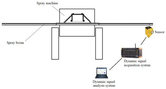
Figure 6.
Test system.
This test was carried out on a spacious concrete pavement, which is beneficial to ensure the integrity of the excitation signals required for the test. The square obstacles set on the concrete pavement are harsher than the actual working environment of the boom sprayer. During the test, the two front wheels of the boom sprayer passed through a 0.1 × 0.1 m square obstacle at three speeds of 4, 6, and 8 . Six sets of tests were performed on the three speeds. Figure 7 shows the scene of the field tests. The tests were performed under good weather with temperature around 18 °C and a light breeze.
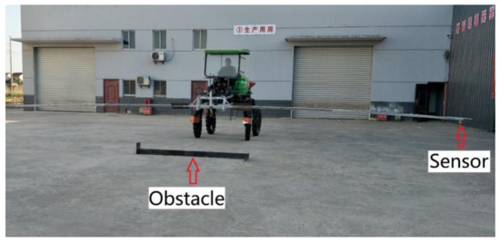
Figure 7.
The scene of tests.
3. Results and Discussion
3.1. Model Validation
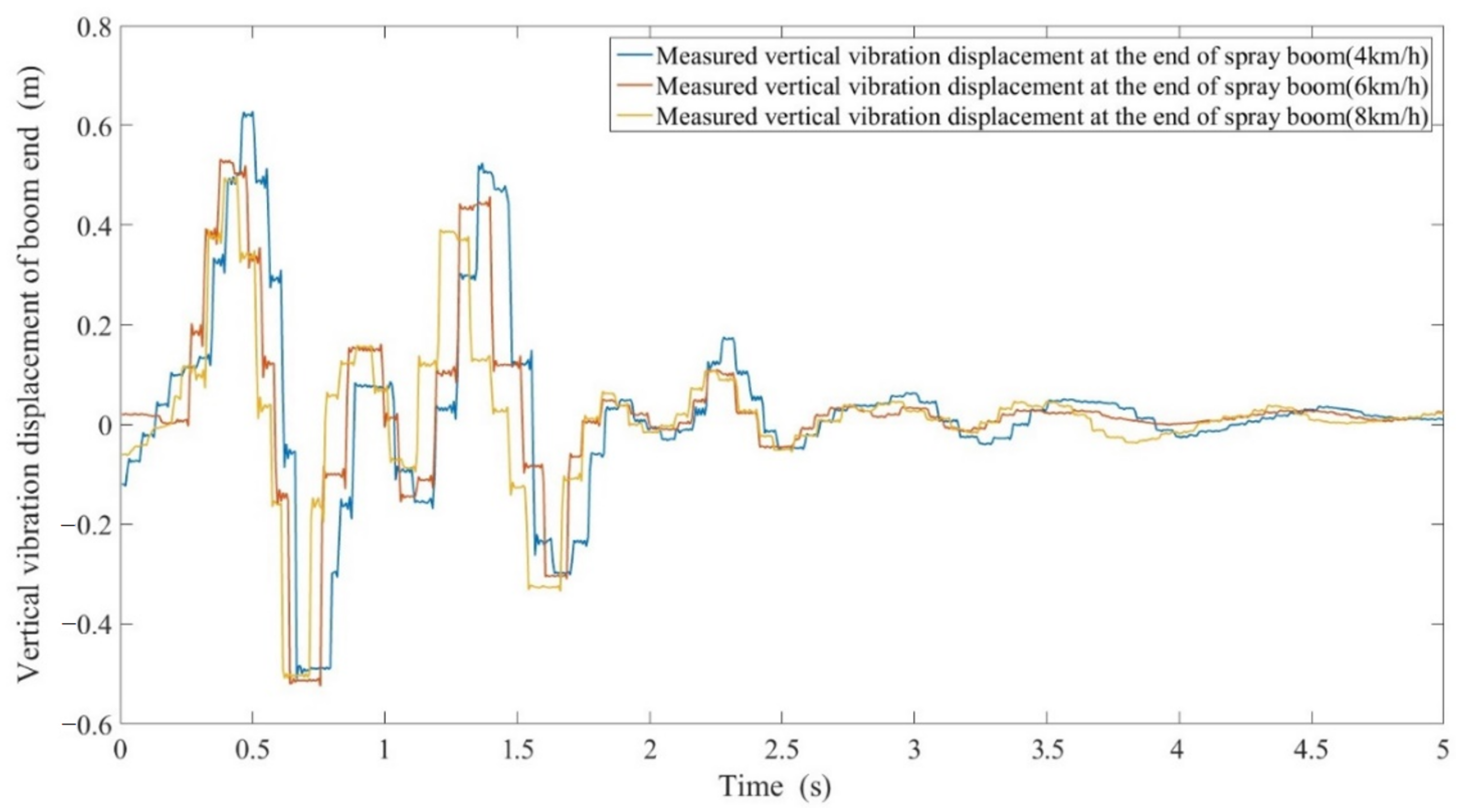
Vertical vibration of the extremity of the spray boom was tested on the ground (Figure 7), and 18 groups of response data were obtained. The effective data time is less than 5 s. Results show that the spray boom is affected by engine vibration and other external factors when the boom sprayer is running on horizontal ground. The maximum allowable vibration error at the extremity tested by the ultrasonic sensor is ±0.05 m. The typical vibration response curves of the spray boom at the first 5 s of three speeds are illustrated in Figure 8. When the boom sprayer passes through obstacles at a traveling speed of 4 , the vibration at the extremity of the spray boom maximizes, which is about 0.628 m upward vibration. With an increase in the traveling speed, the vibration amplitude of the extremity decreases and is reduced obviously, especially when the speed is accelerated from 4 to 6 . Under the three speeds, the maximum amplitude of downward vibration at the extremity changes very little and is about 0.537 m. As the traveling speed of the boom sprayer rises, the frequency of the extremity of the spray boom is increasing, further proving that the spray boom and suspension can drive the spray boom to follow the low-frequency components of the ground, while isolating the fluctuation and inclination of high-frequency components. The vibration curve shows that the spray boom during vibration is affected by different parts of the boom sprayer body, spray boom suspension and vibration frequency, resulting in the interval small amplitude vibration. Due to the relative friction caused by the relative motion of each part of the boom sprayer in the vibration, the vibration waveform clips and distorts. The vibration of the spray boom is mainly concentrated in the first 3 s and decays rapidly after 3 s.
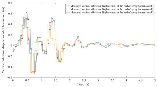
Figure 8.
Vibration response curves of the extremity of the spray boom when the boom sprayer passes through obstacles at three speeds.
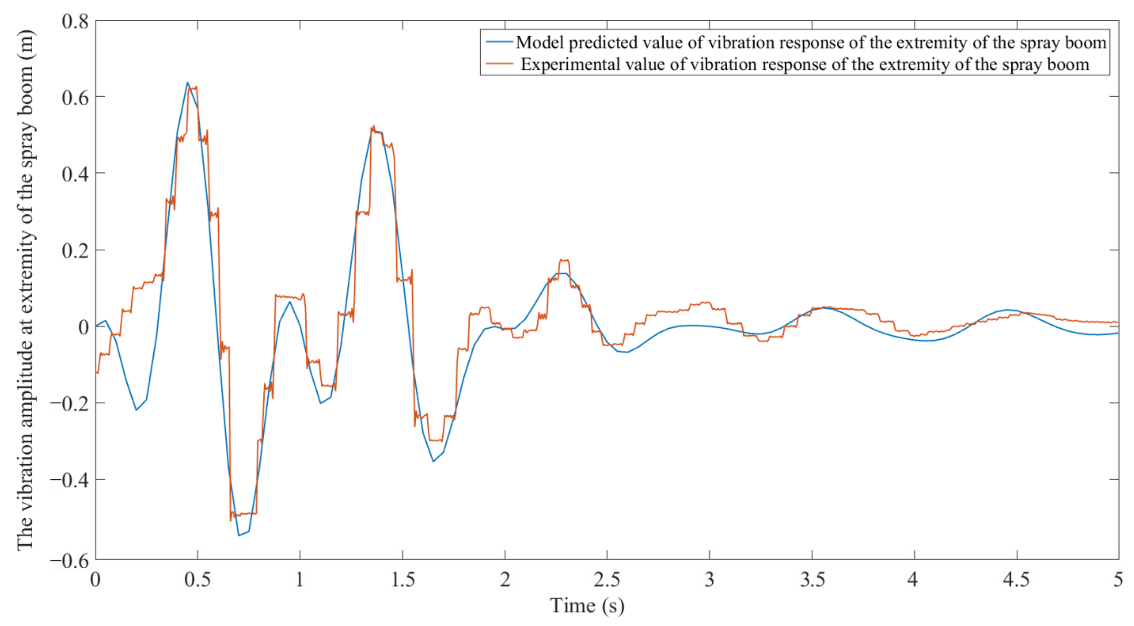
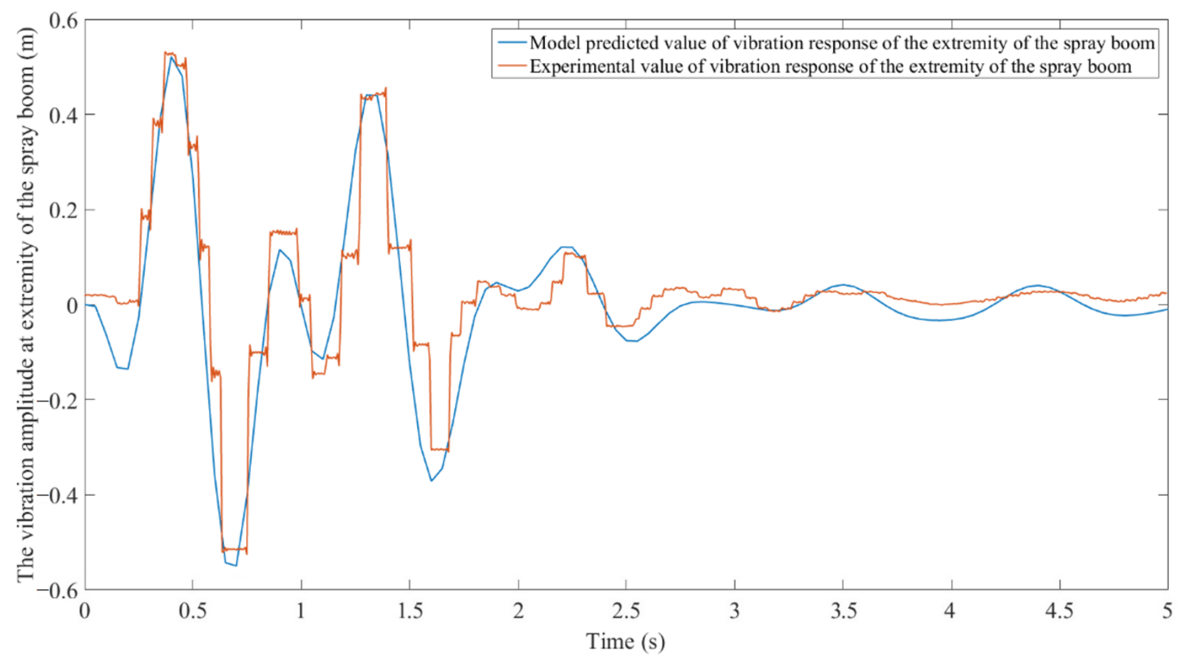
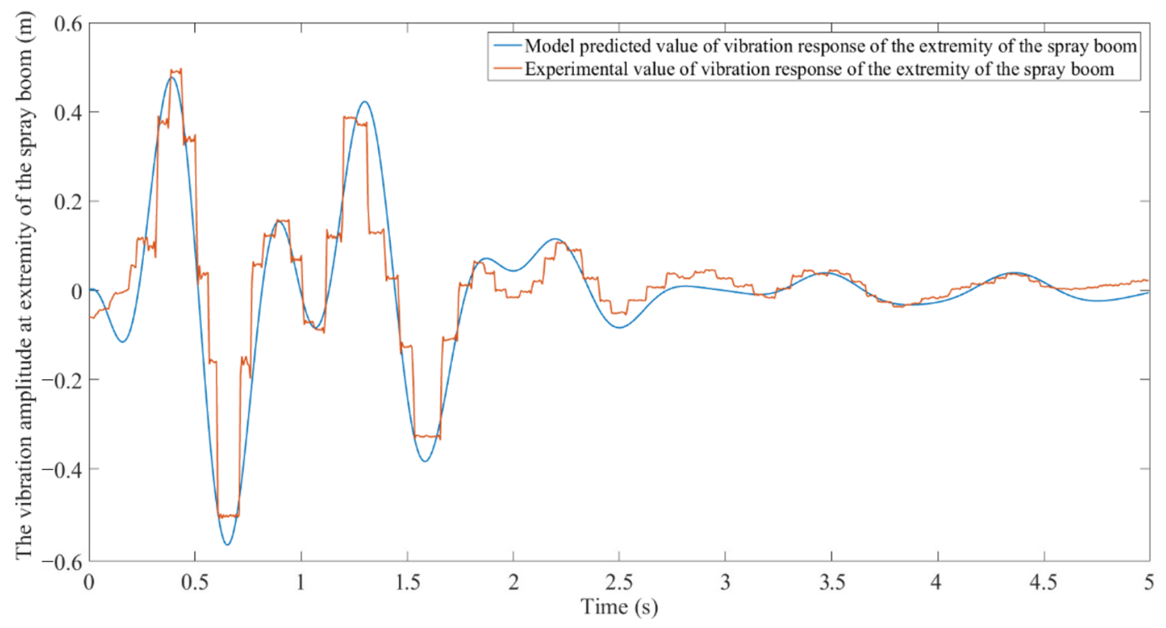
Figure 9, Figure 10 and Figure 11 compare the measured vibration response of the spray boom with the model predicted results when the boom sprayer passes through the obstacle at the speeds of 4, 6, and 8 . Among the three vehicle speeds, the correlation coefficient between the model simulation results and the measured results minimizes to 0.917 at 8 . Clearly, the measured vibration distortion waveform at the extremity of the spray boom is larger, and each peak and valley have obvious friction peak shaving. The model prediction curve distortion waveform is less but has friction peak shaving at each peak and valley. The main reason for this difference is that when the boom sprayer passes through the obstacle, an unpredictable random collision friction occurs between relevant components. The maximum error between the model prediction and the measured values occurs when the boom sprayer passes through the obstacle at the speed of 8. The upward and downward errors are 0.0618 and 0.0238 m, respectively, which are within a reasonable range. Thus, the model can effectively predict the vertical vibration of the spray boom.
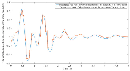
Figure 9.
Model predicted values and experimental values of vibration response of the extremity of the spray boom when the boom sprayer passes through obstacles at 4 .
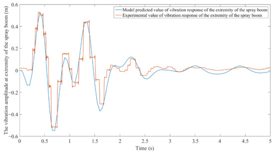
Figure 10.
Model predicted values and experimental values of vibration response of the extremity of the spray boom when the boom sprayer passes through obstacles at 6 .
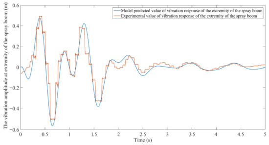
Figure 11.
Model predicted values and experimental values of vibration response of the extremity of the spray boom when the boom sprayer passes through obstacles at 8 .
Through experimental comparison, the model can effectively predict the vertical vibration of the spray boom. The geometric continuous model of the spray boom based on multi-body vibration can improve the efficiency of the parameterized design of the boom sprayer and improve the running stability of the boom sprayer. At the same time, it can be found that there is still room for further improvement in the microscopic accuracy of the model established in this paper. This model can accurately reflect the trend of peak clipping and distortion when predicting the vibration response of the spray boom, but it cannot accurately describe the peak clipping and distortion phenomenon, which is the focus of future research.
3.2. Analysis of Influence of Boom Sprayer Speed on Vibration of the Spray Boom
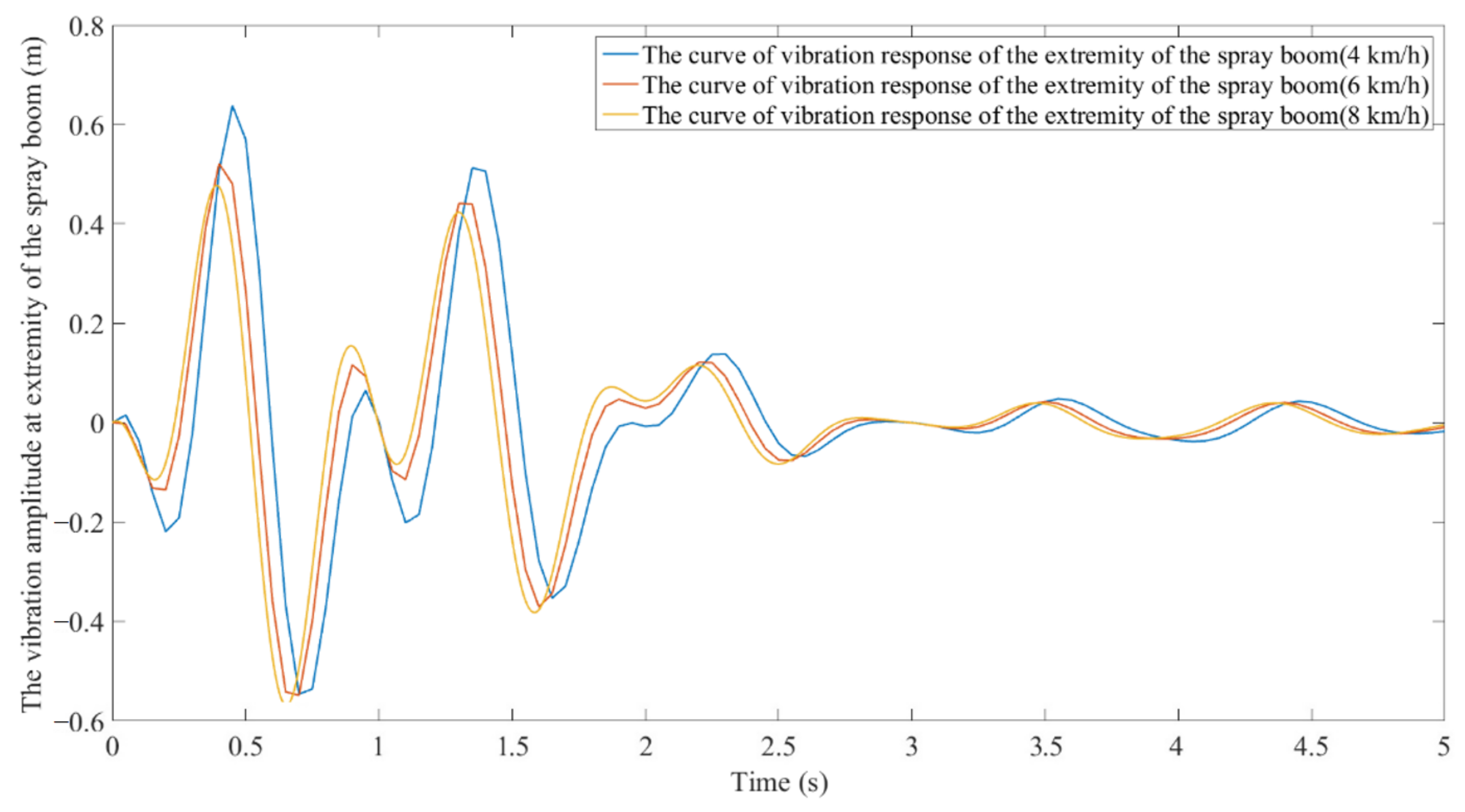
When the boom sprayer passes through the obstacle at a certain speed, it is as if it is subjected to a step excitation, and the upward force of the obstacle on the boom sprayer can be determined by the multi-body simulation on RecurDyn. The speed of the boom sprayer is about 6 in the field operation. On RecurDyn, the force of the front axle when the boom sprayer passed through a 0.1 × 0.1 m obstacle at 4, 6 or 8 was simulated. Results show the upward force on the front axle is about 4800, 5200, 6320 N, and the time for the front wheels to pass through the obstacle is about 0.09, 0.06, and 0.045 s, respectively. Relevant parameters were substituted into the vibration model of the spray boom, and the vertical vibration displacement curves of the extremity of the spray boom at 4, 6, and 8 were plotted (Figure 12).
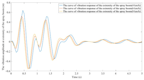
Figure 12.
Model predicted values of the vibration of the extremity of the spray boom when the boom sprayer passes through obstacles at different speeds.
When the boom sprayer passes through the obstacle, the vertically vibrating spray boom returns to its equilibrium position in about 5 s (Figure 12). After the spray boom is impacted, the vibration decay speed is related to the material characteristics and the vibration characteristics of the suspension of the spray boom [11,25,26]. Therefore, during simulation, the vertical vibration curve of the spray boom in the previous 5 s was taken. Comparison of vertical vibration curves at three speeds demonstrates that with an increase in the traveling speed of the boom sprayer, the amplitude of vertical vibration at the extremity of the spray boom decreases, and the vibration period is shortened. However, when the traveling speed is accelerated from 6 to 8, the downtrend of vertical vibration amplitude at the extremity of the spray boom and the downtrend of vibration period are slowed down. This further proves that the spray boom and suspension can drive the spray boom to follow the low-frequency components of the ground, while isolating the fluctuation and inclination of high-frequency components corresponds to the characteristics of the weak damping structure of the spray boom [5,11,26]. When the boom sprayer passes through the obstacle at a speed of 4, the vertical vibration amplitude at the extremity of the spray boom maximizes to 0.638 m upward. Due to the differences and vibration superposition between the upper and lower vibrations of the boom sprayer body and the vertical vibration frequencies of the spray boom, the spray boom is interfered by the upper and lower vibrations in the vertical vibration and the elastic deformation of the spray boom, resulting in small amplitude fluctuation at intervals [26,27].
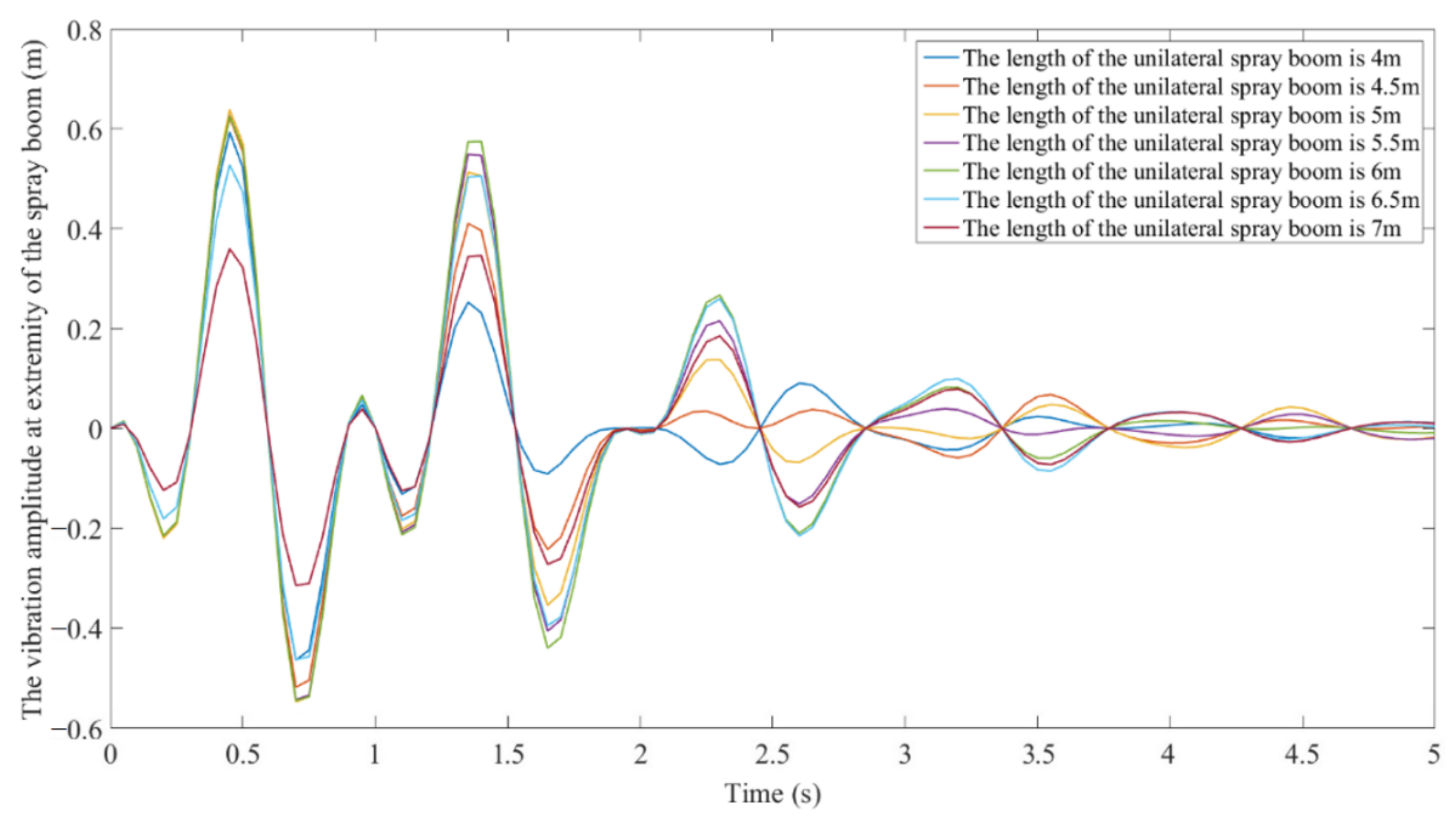
3.3. Analysis of Influence of Spray Boom Length on Spray Boom Vibration
The previous section verifies the accuracy of the geometric continuous model of the spray boom based on multi-body vibration. This section discusses the influence of lengths of the unilateral spray boom on the vertical vibration of the spray boom. Figure 13 shows the vertical vibration at the extremity of the unilateral spray boom with seven lengths of type A cross-sectional structure when the boom sprayer passes through 0.1 × 0.1 m square obstacles at a speed of 6 . With an increment in the length of the unilateral spray boom, the amplitudes of the first and second peaks of vertical vibration increase slightly and greatly respectively, indicating that when the cross-section is the same, the elastic deformation of the spray boom is intensified with the increase in its length resulting in increased amplitude at the extremity of the spray boom [28,29,30,31]. When the length of the unilateral spray boom reaches 5 m, the first peak amplitude maximizes and then decreases. When the length of the unilateral spray boom reaches 6 m, the amplitude of the second peak maximizes and then declines. Hence, when the unilateral spray boom is longer than 6 m, with the increase in the length of the spray boom, the spray boom is more prone to elastic deformation under excitation. The influence of excitation on the extremity of the spray boom is gradually reduced when the length of the spray boom exceeds the strength support range of the spray boom structure, and the elastic deformation of the spray boom will inhibit the vibration transmission to the extremity of the spray boom [30,31]. At present, the length of unilateral spray booms manufactured by various manufacturers is less than 6 m.
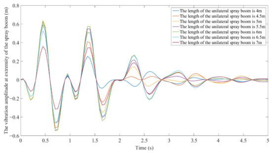
Figure 13.
Model predicted results of the vibration of the extremity of type A cross-section spray boom of different lengths when the boom sprayer is subjected to a step impact.
3.4. Analysis of Influence of Cross-Section Shape on Vibration of the Spray Boom
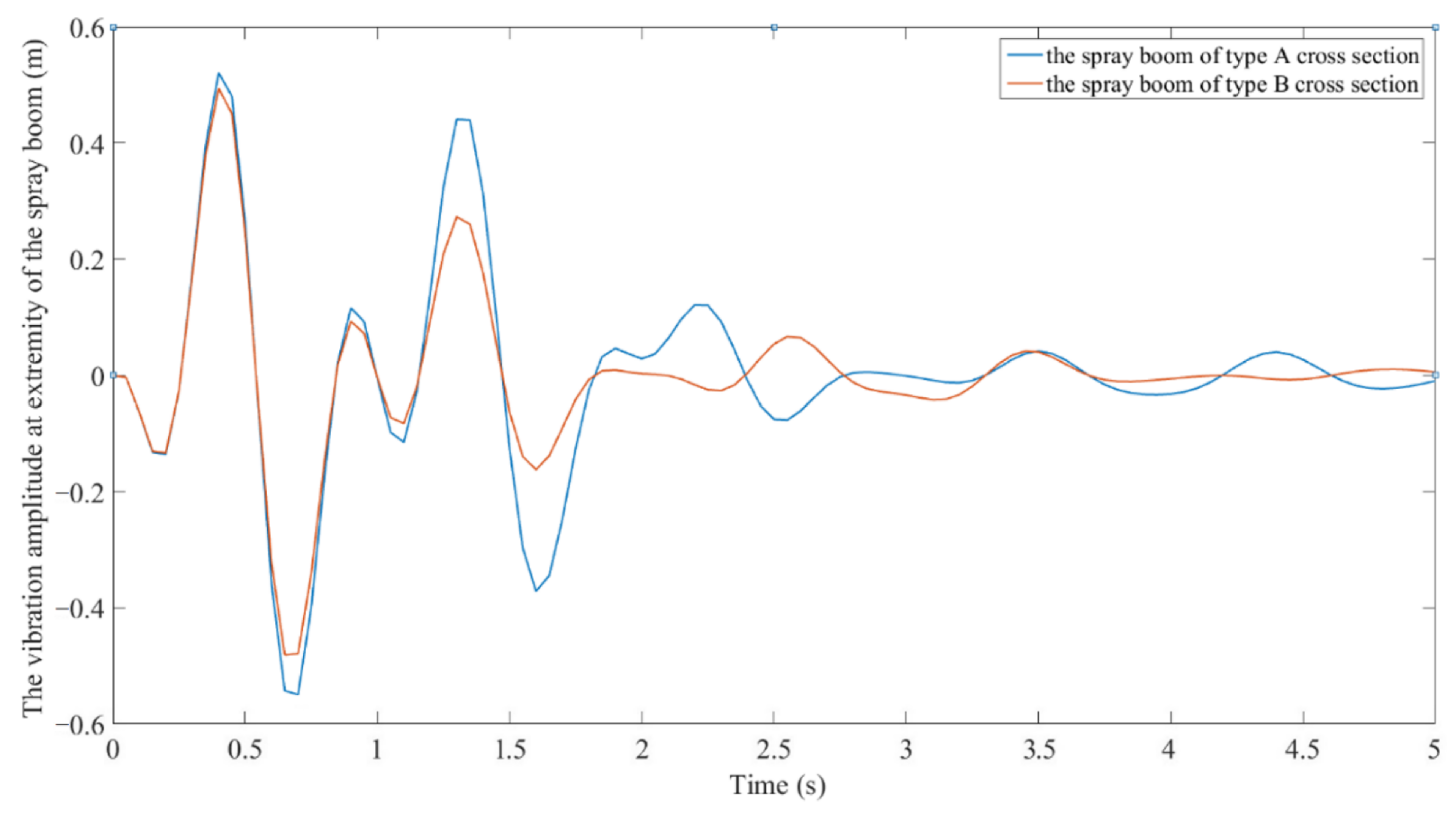
At present, boom sprayers produced by different manufacturers mainly adopt two types of cross-section spray booms (Figure 4). The new geometric continuous model of spray booms based on multi-body vibration is used to analyze the vibration of the spray boom with two cross-sectional structures. Figure 14 shows the vibration of the extremity of the spray boom with a unilateral length of 5 m when the boom sprayer passes through a 0.1 × 0.1 m square obstacle at a speed of 6 . The maximum vibration amplitudes of the two types of spray booms are only slightly different, but the vibration decay speed of the spray boom of type B cross-section is faster compared with type A cross-section. Hence, the type B cross-section outperforms the type A cross-section in suppressing vibration. It is proved that the spray boom with a larger cross-section moment of inertia has a better vibration suppression effect under the same material [32,33,34,35].
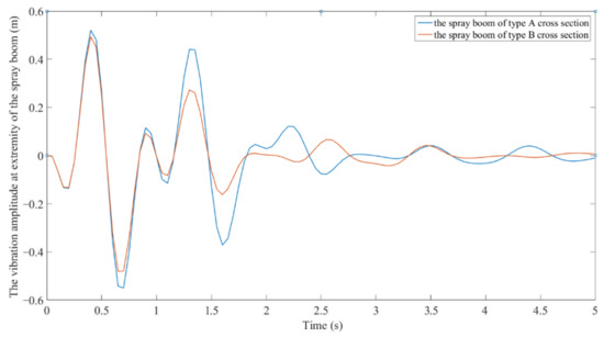
Figure 14.
Model predicted results of vibration of the extremity of the spray boom with different cross-sections when the boom sprayer is subjected to a step impact.
4. Conclusions
A geometric continuous model of the spray boom based on multi-body vibration was established, and its accuracy was verified using building a vibration test system on a Swan3WP-500 self-propelled spray machine, the conclusions were listed below:
- (1)
- The amplitude and period of the vibration at the extremity of the spray boom decrease with an increase in the speed of the boom sprayer, which was determined by analyzing the vibration of the spray boom when the boom sprayer passed through obstacles at different speeds.
- (2)
- When the length of the unilateral spray boom is larger than 6 m, with an increase in the unilateral spray boom length, the spray boom is more prone to elastic deformation upon excitation, and the influence of excitation on the extremity of the spray boom is gradually reduced.
- (3)
- The spray boom with a larger cross-sectional moment of inertia shows a better vibration suppression effect. The ability of the spray boom of two different cross-sections to suppress the step impact was analyzed on the geometric continuous model.
Author Contributions
Conceptualization, J.Y. and X.X.; methodology, L.C.; validation, S.D., W.G. and F.L.; formal analysis, X.X.; investigation, F.L.; resources, J.Y.; data curation, L.C.; writing—draft preparation, J.Y.; writing—review and editing, X.X., L.C., S.D.; visualization, W.G.; supervision, X.X.; project administration, X.X.; funding acquisition, J.Y. All authors have read and agreed to the published version of the manuscript.
Funding
This research was funded by the National Key Research and Development Program of China (grant no. 2017YFD0700905)) and the National Natural Science Foundation of China (grant no. 51605236).
Data Availability Statement
The data presented in this study are available on request from the corresponding author. The data are not publicly available due to privacy restrictions.
Conflicts of Interest
The authors declare no conflict of interest.
References
- Zhuang, T.; Yang, X.; Dong, X.; Zhang, T.; Yan, H.; Sun, X. Research status and development trend of large self-propelled sprayer booms. Trans. Chin. Soc. Agric. Mach. 2018, 49, 189–198. (In Chinese) [Google Scholar]
- Ramon, H.; De Baerdemaeker, J. Spray boom motions and spray distribution: Part 1 derivation of a mathematical relation. J. Agric. Eng. Res. 1997, 66, 23–29. [Google Scholar] [CrossRef]
- Ramon, H.; Missotten, B.; De Baerdemaeker, J. Spray boom motions and spray distribution: Part 2 experimental validation of the mathematical relation and simulations. J. Agric. Eng. Res. 1997, 66, 31–39. [Google Scholar] [CrossRef]
- Langenakens, J.; Clijmans, L.; Ramon, H.; De Baerdemaeker, J. The effects of vertical sprayer boon movements on uniformity of spray distribution. J. Agric. Eng. Res. 1999, 74, 281–291. [Google Scholar] [CrossRef]
- Ramon, H. A Design Procedure for Modern Control Algorithms on Agricultural Machinery Applied to Active Vibration Control of a Spray Boom. Ph.D. Thesis, Department of Agricultural Engineering, K.U., Leuven, Belgium, 1993. [Google Scholar]
- Ramon, H.; De Baerdemaeker, J. A modelling procedure for linearized motions of tree structured multibodies-1: Derivation of the equations of motion. Comput. Struct. 1996, 59, 347–360. [Google Scholar] [CrossRef]
- Ramon, H.; De Baerdemaeker, J. A modelling procedure for linearized motions of tree structured multibodies-2: Design of an active spray boom suspension on a spraying-machine. Comput. Struct. 1996, 59, 361–375. [Google Scholar] [CrossRef]
- Anthonis, J.; Ramon, H. Comparison between two techniques for modelling agricultural spray booms. Math. Control. Appl. Agric. Hortic. 1997, 30, 157–162. [Google Scholar] [CrossRef]
- Anthonis, J.; Ramon, H. Comparison between the discrete and finite element methods for modelling an agricultural spray boom-Part 1: Theoretical derivation. J. Sound Vib. 2003, 266, 515–534. [Google Scholar] [CrossRef]
- Anthonis, J.; Ramon, H. Comparison between the discrete and finite element methods for modelling an agricultural spray boom-Part 2: Automatic procedure for transformingthe equations of motion from force to displacement input and validation. J. Sound Vib. 2003, 266, 535–552. [Google Scholar] [CrossRef]
- Baijing, Q.; Ning, Y.; Xichao, X.; Xianping, G.; Chundun, W. Ideal spray boom response extraction with front and rear tires excited by step track. Trans. Chin. Soc. Agric. Mach. 2014, 2, 55–60. (In Chinese) [Google Scholar]
- Wu, J.; Miao, Y. Dynamic characteristic analysis of boom for wide sprayer with different exciting sources. Trans. Chin. Soc. Agric. Eng. 2016, 28, 39–44. (In Chinese) [Google Scholar]
- He, Y.; Qiu, B.; Yang, Y.; Ma, J. Deformation analysis and control of elastic deformation for spray boom based on finite element model. Trans. CSAE 2018, 30, 28–36. (In Chinese) [Google Scholar]
- Singiresu, S.R. Mechanical Vibrations; Tsinghua University Press: Beijing, China, 2009; pp. 284–416. (In Chinese) [Google Scholar]
- Kising, A.; Ghlich, H. Dynamic characteristics of large tyres. J. Agric. Eng. Res. 1989, 43, 11–21. [Google Scholar] [CrossRef]
- Lines, J.A.; Murphy, K. The stiffness of agricultural tractor tires. J. Terramech. 1991, 28, 49–64. [Google Scholar] [CrossRef]
- Ahwed, O.B.; Goupillon, J.F. Predicting the ride vibration of anagricultural tractor. J. Terramech. 1997, 34, 1–11. [Google Scholar]
- Gang, L.; Zida, Z.; Dingxuan, Z. Experiment alstudy of static characteristics and parameter identification for heavy-duty tires. Constr. Mach. Equip. 2004, 7, 22–29. [Google Scholar]
- Forst, A.R. Simulation of an active spray boom suspension. J. Agric. Eng. Res. 1984, 30, 313–325. [Google Scholar] [CrossRef]
- Donghua, C.; Xiaoxiong, J. Analytic study on nonlinear model for tire stiffness and damping. Chin. J. Construct. Mach. 2004, 2, 408–412. (In Chinese) [Google Scholar]
- O’ Sullivan, J.A. Simulation of the behavior of a spray boom with an active and passitive pendulum suspension. J. Agric. Eng. Res. 1986, 35, 157–173. [Google Scholar] [CrossRef]
- Zhang, J. Dynamic analysis on sprayer boom suspension. Trans. Chin. Soc. Agric. Mach. 1996, 27, 134–138. (In Chinese) [Google Scholar]
- Xie, W.P.; Guo, M.; Sun, L.M. Experimental study on damping characteristics of the steel cantilever beam in the linear elastic range. J. Vib. Eng. 2016, 29, 1011–1019. (In Chinese) [Google Scholar]
- Xu, F.; Huang, W.; Chen, L. Simulation analysis of tire force of wheeled tractor under typical road conditions. Trans. Chin. Soc. Agric. Eng. 2009, 25, 61–65. (In Chinese) [Google Scholar]
- Clijmans, L.; Swevers, J.; De Baerdemaeker, J. Experimental design for vibration analysis on agricultural spraying machines. In Proceedings of the International Conference on Noise and Vibration Engineering, Kissimmee, FL, USA, 8–11 February 1998; Volume 3, pp. 1517–1522. [Google Scholar]
- Cui, L.; Xue, X.; Ding, S.; Qiao, B.; Le, F. Analysis and test of dynamic characteristics of large spraying boom and pendulum suspension damping system. Trans. Chin. Soc. Agric. Mach. 2017, 33, 61–68. (In Chinese) [Google Scholar]
- Ning, Y. Research on Spray Boom Response Modeling and Motion Control. Master’s Thesis, Jiangsu University, Zhenjing, China, 2011. (In Chinese). [Google Scholar]
- Wang, S. The Second Order Theoretical Modeling and Experimental Research of Flexible Manipulator Based on the Moving Boundary. Master’s Thesis, Wuhan University of Technology, Wuhan, China, 2015. (In Chinese). [Google Scholar]
- Wang, Y.; Meng, J.; Marghitu, D.B.; Li, S. Dynamic modeling and numerical simulation of rigid-flexible coupling cantilever beam with vibration response. J. Mach. Des. 2018, 9, 86–92. (In Chinese) [Google Scholar]
- Farokhi, H.; Ghayesh, M.H. Geometrically exact extreme vibrations of cantilevers. Int. J. Mech. Sci. 2019, 7, 2–46. [Google Scholar] [CrossRef]
- Pramod, M. Nonlinear Vibrations of Cantilever Beams and Plates. Ph.D. Thesis, Faculty of the Virginia Polytechnic Institute and State University, Blacksburg, VA, USA, 2003. [Google Scholar]
- Luca, T.; Simon, C.; Steve, H.; Stefan, M.; Tom, A. Effect of materials and design on the bending stiffness of tennis rackets. Eur. J. Phys. 2021, 42, 87–106. [Google Scholar]
- Cheng, Y.; Xue, Z.; Wang, Y. Influence of coupling vibration of tower-large wind turbine blades on wind turbine stability of flexible multibody system. Acta Energ. Sol. Sin. 2019, 8, 2170–2177. (In Chinese) [Google Scholar]
- Zhang, Y.N.; Jing, L.L.; ZHU, H.Y.; Shen, L.Y.; Qian, J.W. On force and deformation of cantilever Y adjustment mechanism of target alignment sensor. Opt. P. Eng. 2018, 8, 2030–2038. (In Chinese) [Google Scholar]
- Wang, J.; Yao, F.; She, Z. Influence of section size on buckling stability of telescopic boom. Chin. J. Cons. Mach. 2018, 4, 305–310. (In Chinese) [Google Scholar]


Publisher’s Note: MDPI stays neutral with regard to jurisdictional claims in published maps and institutional affiliations. |
© 2021 by the authors. Licensee MDPI, Basel, Switzerland. This article is an open access article distributed under the terms and conditions of the Creative Commons Attribution (CC BY) license (https://creativecommons.org/licenses/by/4.0/).