Article

Experimental Study of Primary Atomization Characteristics of Sonic Air-Assist Atomizers

Faculty of Technology, Natural Sciences and Maritime Sciences, University of South-Eastern Norway, 3936 Porsgrunn, Norway
*
Author to whom correspondence should be addressed.
Appl. Sci. 2021, 11(21), 10444; https://doi.org/10.3390/app112110444
Submission received: 6 October 2021 / Revised: 29 October 2021 / Accepted: 1 November 2021 / Published: 6 November 2021

Abstract

:

Featured Application

Sonic twin-fluid atomizers are used in industrial applications as high viscosity liquids (diesel) or molten metals employing high-speed airflows for efficient atomization.

Abstract

The present study compares two twin-fluid atomizer concepts based on the airflow (shock waves) pattern obtained through shadowgraph imaging for atomization of water with a low air/water pressure supply. The research work was conducted using the backlight imaging technique for converging (sonic) and converging–diverging (supersonic) air-assist atomizers with a 3.0 mm (throat) diameter. An annular sheet of thicknesses 70 µm and 280 µm with a high-speed air-core was employed to study the breakup dynamics for different water mass flow rates (100–350 kg/h) and air mass flow rates (5–35 kg/h). Different sheet breakup patterns were identified as the function of the ALR ratio (air-to-liquid mass flow), liquid Weber number (WeL), and Reynolds number (Reg). Different breakup modes extend from canonical Rayleigh bubble breakup, ligament-type breakup, to the pure pulsating breakup via annular sheet disintegration. The sheet breakup dynamics were studied in terms of spray angle and breakup length. With higher ALR values, breakup length showed a decreasing trend, while spray angle showed an increasing trend in the converging and converging–diverging (CD) air-assist atomizers, respectively, owing to the drastic difference in the jet flow dynamics.

1. Introduction

Twin-fluid atomization is widely used, especially for heavy (viscous) Newtonian fluids or non-Newtonian fluids. The merit of a twin-fluid atomizer is low-pressure requirements compared with the mechanical counterpart, at the expense of an external source of atomizing fluid (air) for high-speed twin-fluid interaction. Earlier studies showed that a sheet breakup is more optimal for good atomization than a jet breakup [1]. Many researchers have studied sheet breakup, mainly in two types—flat sheets or annular sheets. However, flat sheets gained more attention in the early days because of their classical problem structure. Lately, the annular sheet has also received some attention. Two major distinctions were thoroughly studied—inner air and outer air configuration, in which inner air is proven to be more effective in promoting sheet instability [2,3].
Based on the inner/outer air velocity or momentum, many modes or breakup patterns were identified. Kawano et al. [4] investigated the sheet breakup and found two modes based on a critical air velocity—liquid lump and liquid film. Choi et al. [5] observed three breakup modes—Rayleigh, bubble-breakup, and pure-pulsating depending on relative air and liquid rates. A photographic investigation by Adzic et al. [6] categorized breakup into Kelvin–Helmholtz (a new regime–christmas tree), cellular, and atomization. Three flow regimes for the annular jet breakup process have been identified by Li et al. [7], i.e., bubble formation, annular jet formation, and atomization. Ligament spacing is wider for thick sheets, especially in an annular sheet case such as that investigated by Berthoumieu et al. [8]. Leboucher et al. [3,9] thoroughly studied the breakup based on air–liquid momentum and found modes such as Rayleigh, bubble, christmas tree, and pure pulsating. Zhao et al. [10] discerned the breakup modes—bubble, christmas tree (cellular), and fiber breakup—based on morphological differences. Recent studies [11,12] also employing the central air core demonstrated that the swirling of annular liquid sheets does not significantly influence the sheet breakup dynamics. However, these studies were performed without considering the air-assist mechanism. Kihm et al. [13] and Park et al. [14] first investigated the sonic atomization concept to study effective atomization with a liquid jet using shock wave dynamics in underexpanded or overexpanded flows. Though the Sauter mean diameter decreases after the advent of shock patterns, it still questioned the use of a transonic or supersonic jet with the aim of optimal atomization. Lately, some researchers [15] have studied the gas flow field distribution effects of transonic flow on the liquid metal atomization, finding that the higher gas flow velocity in converging–diverging (CD) atomizers results in smaller particle sizes.
This study aims to discern the various breakup modes or patterns in light of effective atomization using sonic and supersonic flow, as they depict different shock dynamics. This paper contains the experimental findings using a novel concept of sonic atomization employing an annular liquid sheet, whereas earlier studies employed a two-dimensional sheet [13] or jet [16]. Different breakup modes of the liquid sheet with co-flow air were observed and subjected to different air and water flow rates (air-to-liquid ratio (ALR)). Spray breakup dynamics was investigated in terms of spray angle and breakup length with different sheet thickness using converging and converging–diverging (CD) atomizers.

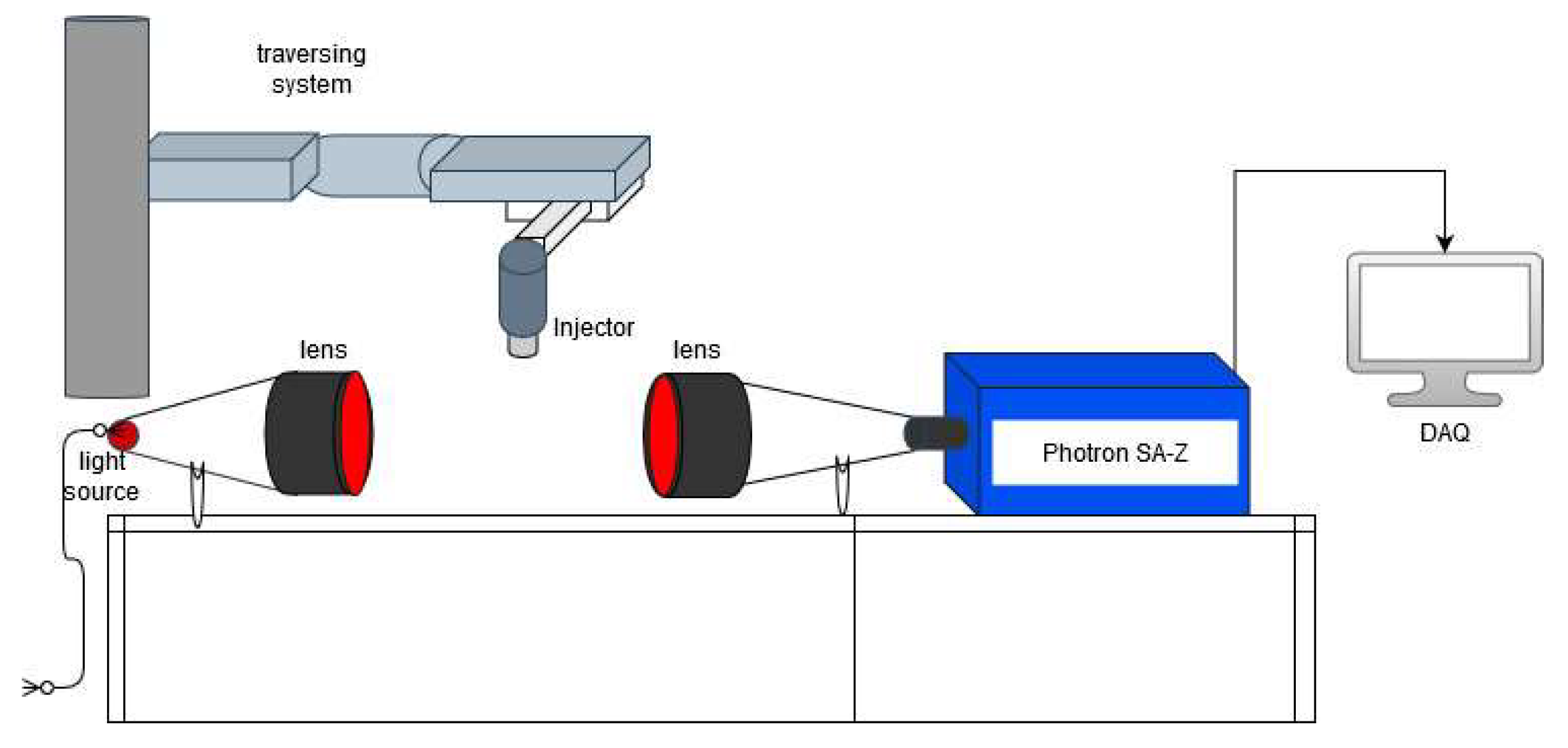
2. Materials and Methods

Converging and converging–diverging (CD) atomizers are employed, as shown in Figure 1. The exit (throat) diameter for both the converging atomizer and CD atomizer is 3.0 mm. The exit diameter for the CD atomizer is 6.0 mm, thus the area ratio (A/A*) is 2.0. The Mach number for the perfectly expanded flow based on the isentropic relation given by Equation 1 (Section 3.1.1) is 2.19. The maximum Mach number or maximum operational pressure employed for the study is 1.80 or 5.79 bar (g), respectively. The high-speed air core and liquid sheet (annular) interaction are shown in Figure 1c.
The schematic for the experimental setup for the gas flow study is shown in Figure 2. A red colour led light (3.0-Watt power) was used as a light source, and the light emitted then passed through a collimated illuminator lens (Opto engineering) of 100 mm in diameter. This lens provides uniform illumination and a reduction in edge diffraction effects. Then, after penetrating a high-speed air jet, the light was collected by another telecentric lens of the same diameter connected to the CMOS-based Photron SA-Z camera with an adapter at the end. Shadowgraph imaging was performed at 21,000 frames per second with a shutter speed of ~50 µs.
The schematic diagram for the backlight shadow imaging setup is shown below (see Figure 3). The atomizers tested were of two types—converging and converging–diverging (CD) air-assist atomizers with core airflow (3.0 mm throat diameter) and liquid (water) injected through an annular gap (coaxial arrangement between atomizer body and the cap). The nozzle was connected at the end of a lance mounted onto the traversing system from Bosch Rexroth (Figure 3). To study the breakup process, two different sheet thicknesses, 70 μm and 280 μm, were employed to examine the sheet velocity (momentum) effects at employed flow rates. A displacement pump (Froster AS company) supplied the liquid after passing through a filter. The liquid mass flow rate was regulated by altering the frequency of the pump, which was recalibrated for uncertainty in flow rates (<1%) for a given mass flow rate. The air was drawn through an in-house installed compressor with a maximum capacity of 100 psi (7.0 bar(g)). Coriolis type flowmeters from Yokogawa Rotamass and Endress Hauser Promass 83 were used for both air and water flow rate measurements. The spray ejected from the atomizer was collected in a box container; then, it was again pumped to the injector through the hose.
The backlight imaging method was adopted to provide the necessary insight into the near-nozzle dynamics. The diffuser screen provided a diffused uniform background for image acquisition with two halogen lights (dedolight dedocool), 250 W each. Photron CMOS-based high-speed camera SA-Z model was employed to capture the images with a 135 mm Nikon Micro lens employed to acquire a field of view (FOV) with a dimension of 15 cm × 15 cm at the frame rate of 8000 frames per second with a shutter speed of 125 μs. However, it is not enough to capture instantaneous images at higher flow rates per the Nyquist sampling criterion, but instantaneous images that are good enough for the primary breakup study must be captured. Water and air were used as working fluids. The properties of fluids are assumed as per the tabled values at STP (20 °C), such that liquid viscosity (µ) = 1.0 × 10⁻³ Ns/m2 and surface tension (σ) = 0.072 N/m in the current study. The liquid flow rate varied from 100 kg/h to 350 kg/h, whereas the airflow rate varied from 1 kg/h to 35 kg/h with the corresponding liquid Weber number (Wel) of 17.2 to 844.9, respectively, which also corresponds to the air-to-liquid ratio (ALR) ranging from 0.00285 to 0.35. The main objective is to examine the effect of the sonic (converging) or supersonic (CD) air-assist atomizer on the annular sheet breakup and the resulting spray pattern. The major difference in both types of nozzles is that the converging type nozzle, after the nozzle is choked, develops the underexpanded sonic jet (Pexit > Pambient), which forms a Prandtl–Meyer expansion fan at inception. In contrast, the CD nozzle goes through overexpansion (Pexit < Pambient), resulting in the initial formation of oblique shock waves. Thus, both configurations belong to a unique class that may result in entirely different breakup characteristics for the novel atomizer. A series of experiments with varying flow rates were performed to find out which configuration is more suitable for better primary atomization capability. All the ranges are mentioned in Table 1.

3. Results

3.1. Flow Dynamics

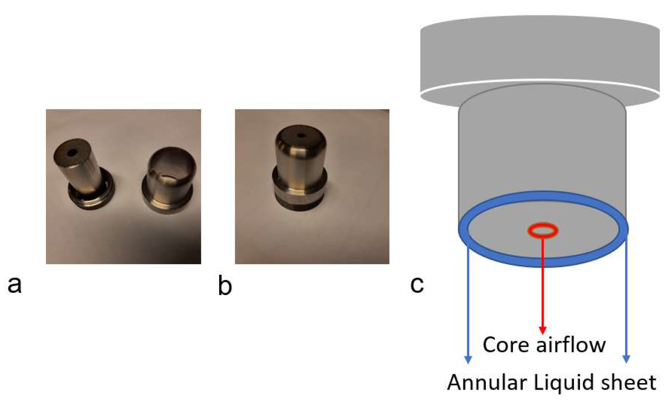
3.1.1. Gas Flow Study

The primary breakup mechanism for the two kinds of atomizers tested was conjectured to be different owing to the distinct jet characteristics. In the converging atomizer, an underexpansion flow pattern is shown in Figure 4a, which results in the Prandtl–Meyer expansion waves [17] with the Mach disc visible (Figure 4). The irregular pressure distribution pattern may try to deflect the liquid sheet in and out of the centerline, thus delaying the sheet contraction (owing to the surface tension effect) even at low liquid flow rates. Besides, owing to the shear force between the air and liquid sheet, it might form instability waves on the inner side of the annular sheet, which gradually performs sheet thinning, through which half of the waves are torn off (like a planar sheet) when wave amplitude reaches a critical threshold, forming ligaments, which further disintegrate to form large globules/droplets depending on the aerodynamic interaction between the high-speed air-jet and ligaments.
On the other hand, the converging–diverging (CD) nozzle undergoes mild overexpansion (as seen in Figure 4b) for the higher airflow rates employed, thus forming the oblique shock waves (diamond shock cells) pattern up to certain downstream near the nozzle exit with a high interface strength of the jet boundary. This jet boundary interface strength might play two roles: firstly, forming sufficiently high amplitude unstable waves (Kelvin–Helmholtz instability) on the sheet surface. Secondly, the irregular pressure distribution due to the alternate compression and expansion of the air-jet may drive the sheet into sudden acceleration and sudden retardation, which corresponds to the alternate sheet deflection towards and away from the centerline of the jet; thus, irregularly shaped liquid parcels might tear off from the sheet. The length of the sonic jet region (Figure 1) can also affect the primary breakup, which eventually affects the secondary atomization [16].
The maximum operational Mach number (M) values based on the total pressure-Mach number (Pt - M) relation employed [18] are given by Equation (1).
P t P = ( 1 + γ 1 2 M 2 ) γ γ 1
where P (=1.0 bar (g)) is ambient pressure and 𝛾 (=1.4) is the ratio of specific heats.

3.1.2. Twin-Fluid Study

The sheet disintegration process is examined for a converging atomizer case with two sheet thicknesses (70 and 280 µm) for a given flow rate (100 kg/h), as shown in Figure 5. The air–liquid interaction gives rise to sheet instability in the form of waviness, which leads to ligaments formation (Figure 5a). The high-speed interaction between the liquid and airflow leads to the high shear layer effects, resulting in the Kelvin–Helmholtz instability waves or Rayleigh–Taylor instability [19] depending upon the side (windward or leeward, respectively) of the ligaments resulting in the very fine mist formation, as seen in Figure 5c,d. Wave growth and ligament formation depend mainly on the surface tension force and aerodynamic forces, which define the droplet size formation further downstream. The sprays exhibit a radial periodic liquid elements’ ejection, attributed to the high-speed core air-jet. The bursting phenomenon (Figure 5) in the converging atomizer is due to airflow behavior. In general, for both above cases, the frequency of the bursting phenomenon at the neck region (which was visually analyzed in this study) may vary depending on the aerodynamic interaction effects, the natural pulsating frequency of the liquid sheet, and pulsations caused by the slight variation in airflow rates (<2%). For the 70 µm sheet, owing to higher axial momentum, the breakup length (which is considered as an indicator of the stability of the liquid sheet) (Figure 5a) is longer than the 280 µm sheet (Figure 5e). With increasing ALR, owing to the high-speed aerodynamic interaction, the mist-like droplets (tiny) formed downstream axially in the 70 µm case (Figure 5c,d), whereas some thread-like droplets (bigger) ejecting laterally out of the sheet are visible with 280 µm sheet thickness (Figure 5g,h). The sheet formed was corrugated/wavy in both of the above cases, forming a cellular pattern (not visible here, whose cell size may depend upon the air jet velocity), as well as stretched-sheet/ligament structure in both the spanwise and streamwise direction (also observed in planar sheet configuration [20,21]), which is attributed to the three-dimensional (3D) nature of the annular sheet. The pressure difference, the surface tension effect, and the aerodynamic forces dictate the liquid sheet breakup characteristics, such as breakup length, spray angle, and so on. For the converging–diverging (CD) atomizer, the sheet breaks up into larger angles for lower fluid flow rates (Figure 6a); with an increase in ALR values, the ligaments/droplets emanate sideways owing to the air jet pattern (Figure 6b). At a higher air-to-liquid ratio (ALR), the coherent pattern of airflow and mist is observed in the near spray centerline, leading to smaller droplet clustering/segregation (Figure 6,d). The neck formation region is more visible at higher fluid flow rates, where then liquid fragments eject radially, forming a larger spray angle (Figure 6f). The boundary layer stripping (Figure 6g,h) is observed at a higher air-to-liquid ratio (ALR) owing to the intense aerodynamic interaction between the fractured/perforated sheet and high-speed airflow, which was also observed in [22].

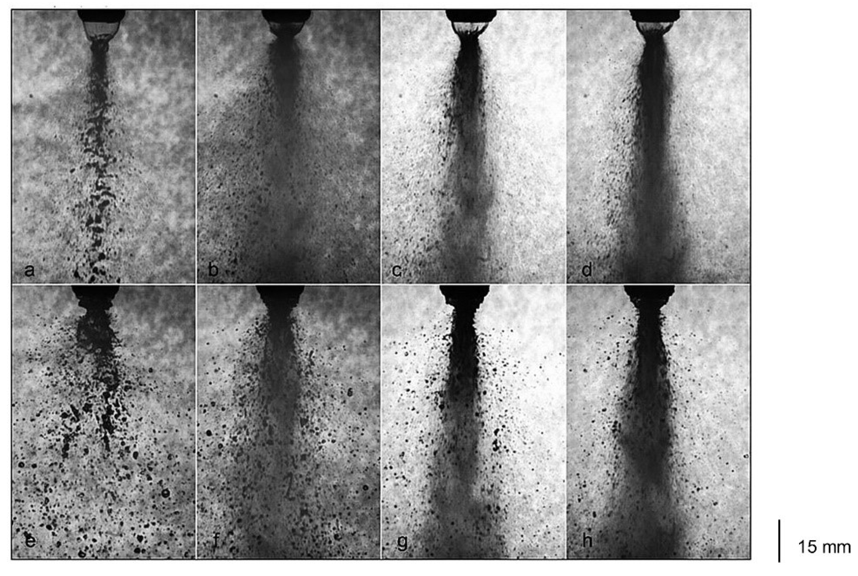
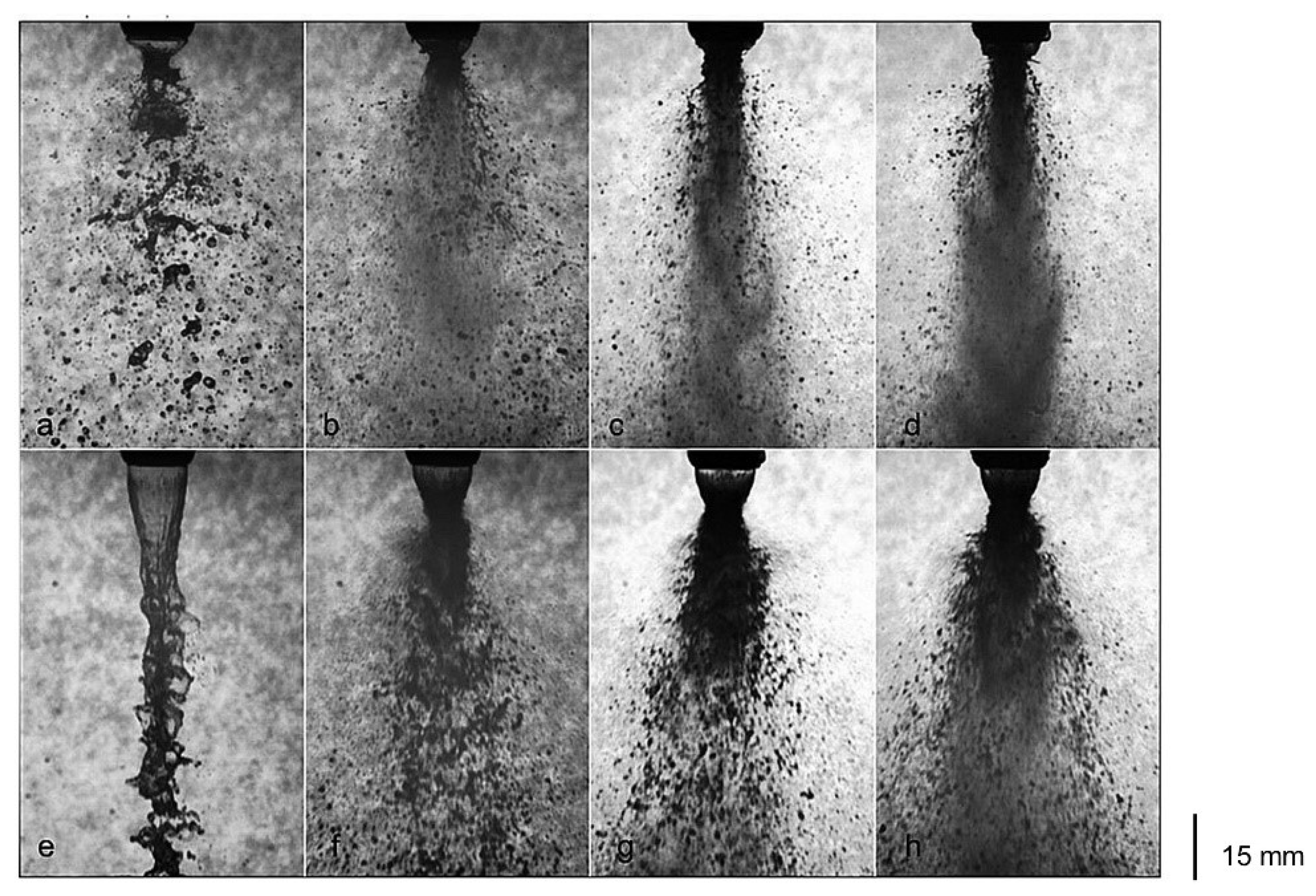
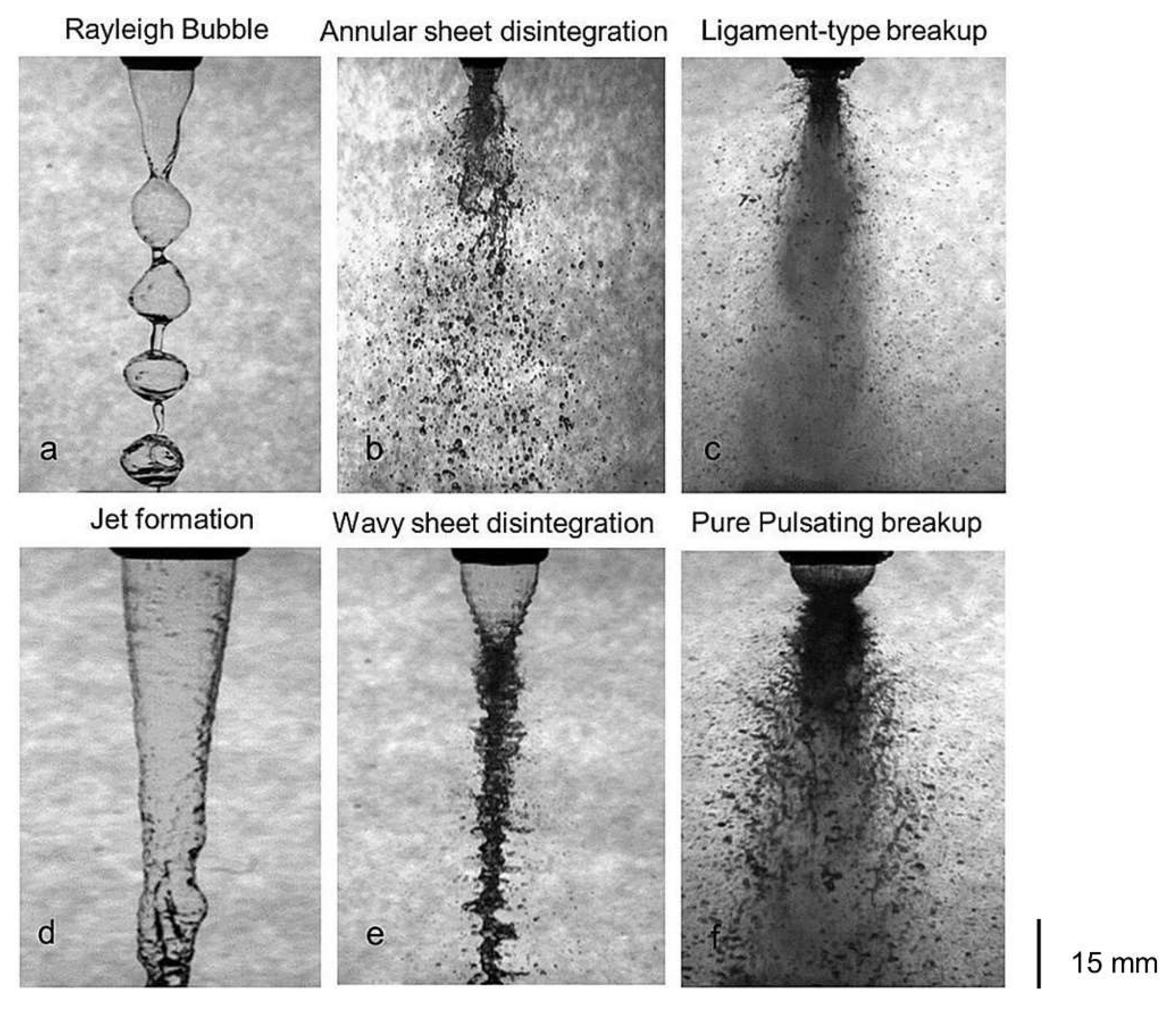
3.2. Sheet Breakup Dynamics

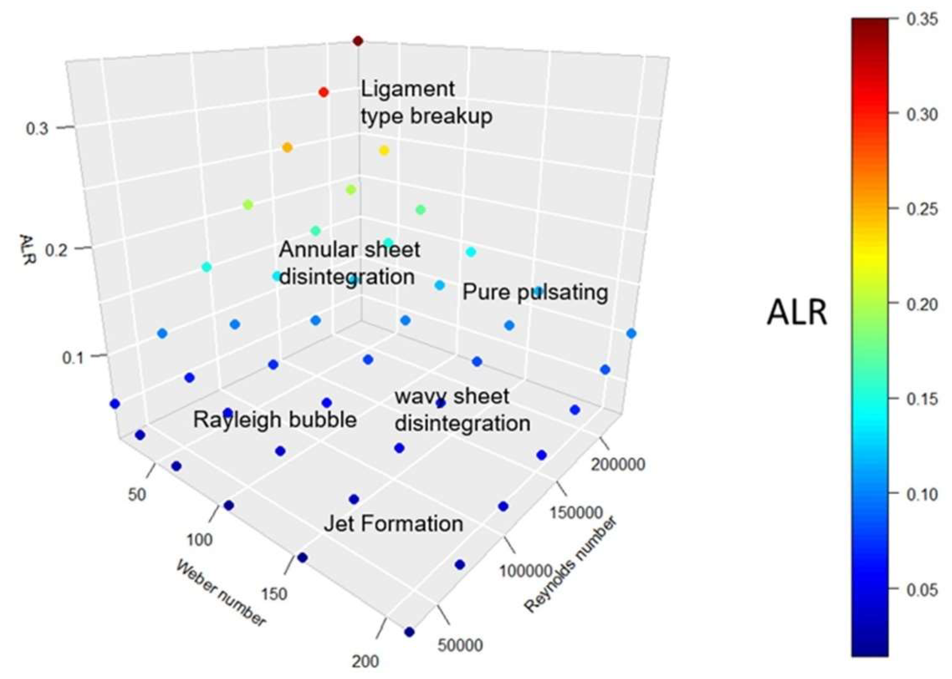
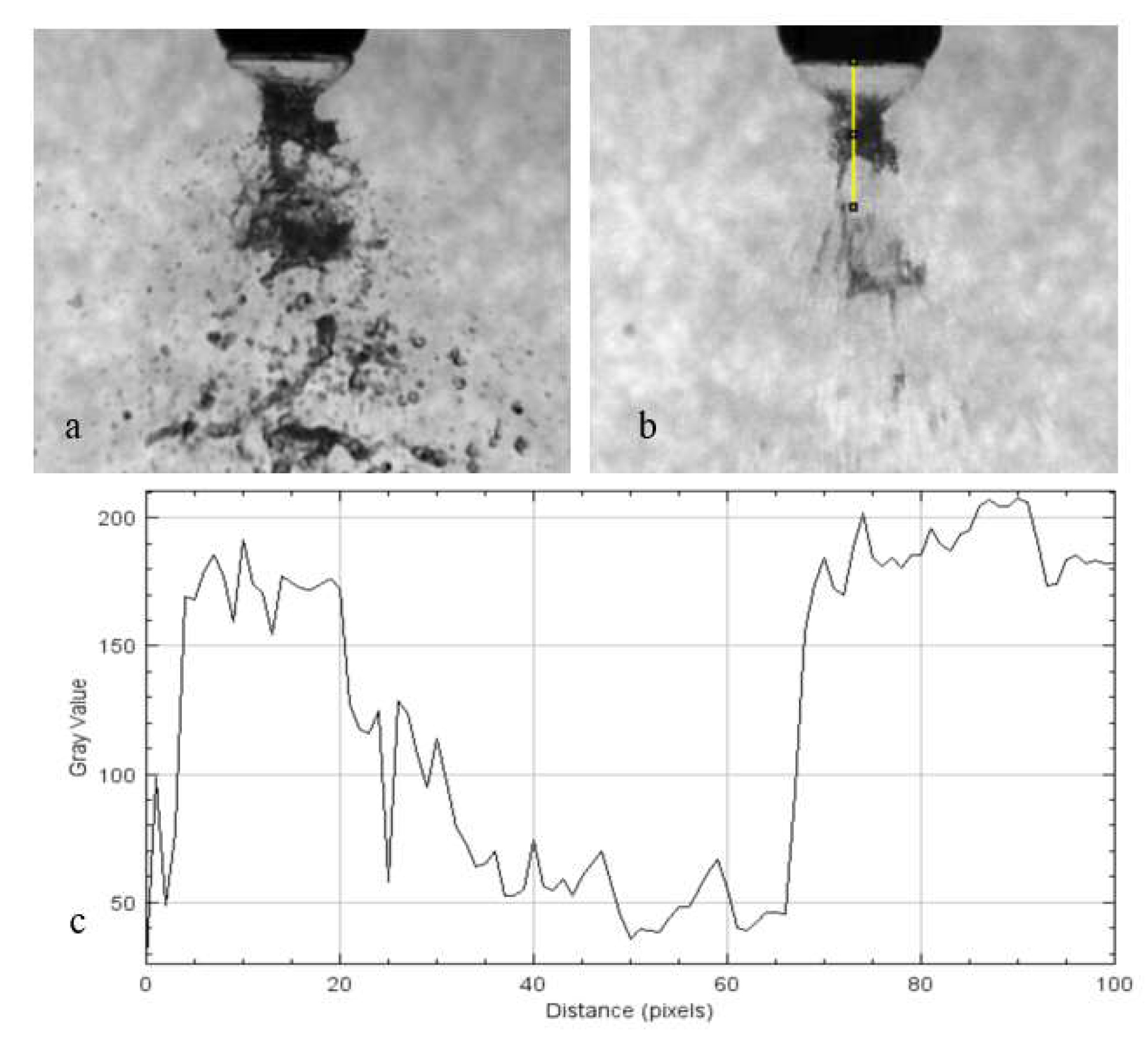
3.2.1. Breakup Morphology
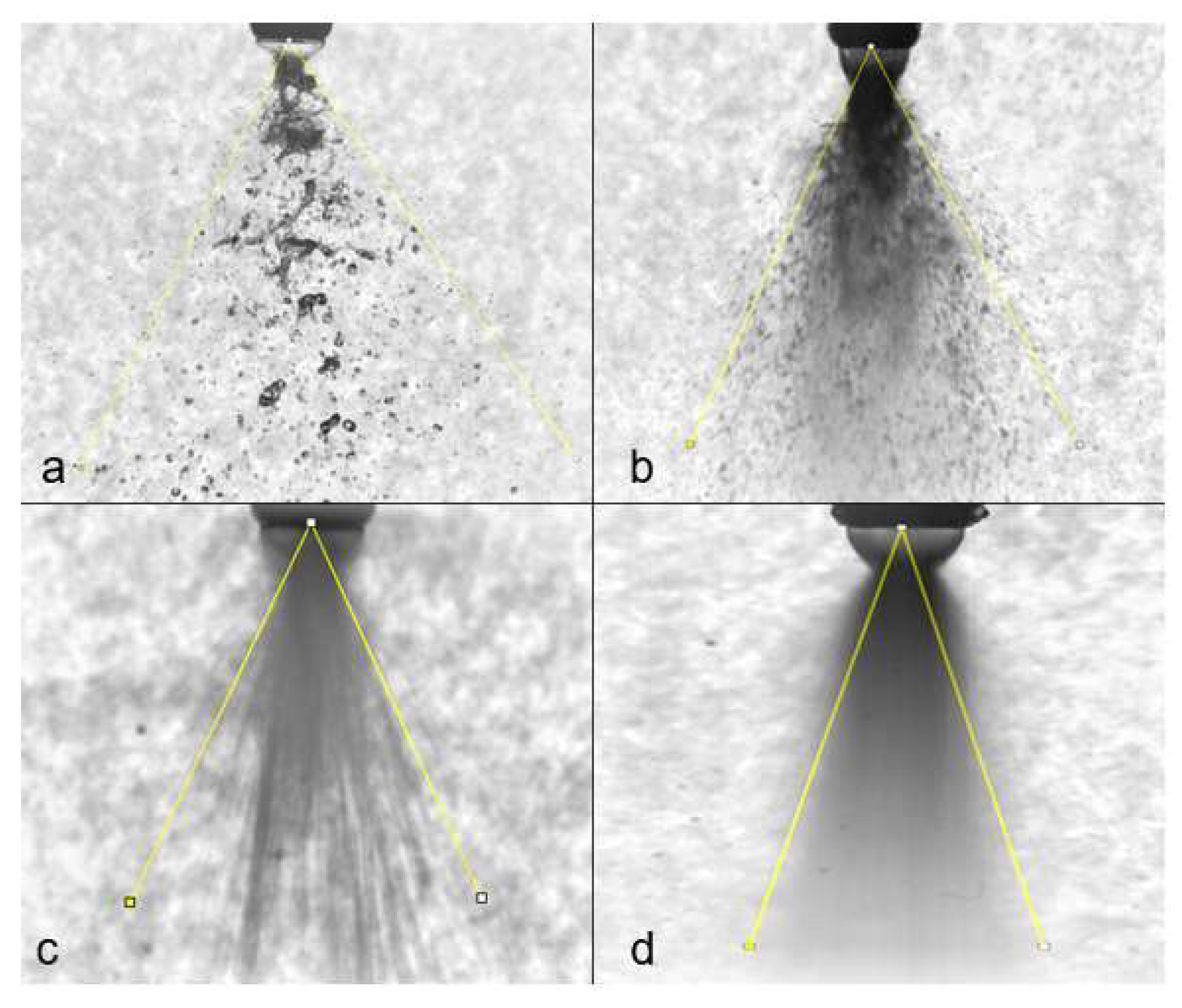
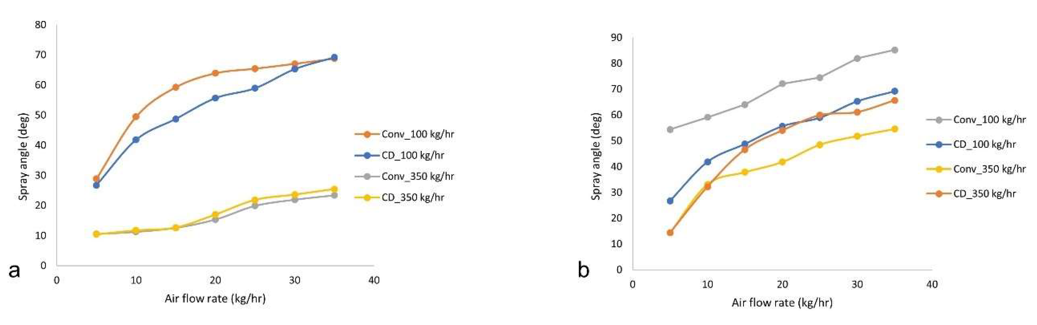
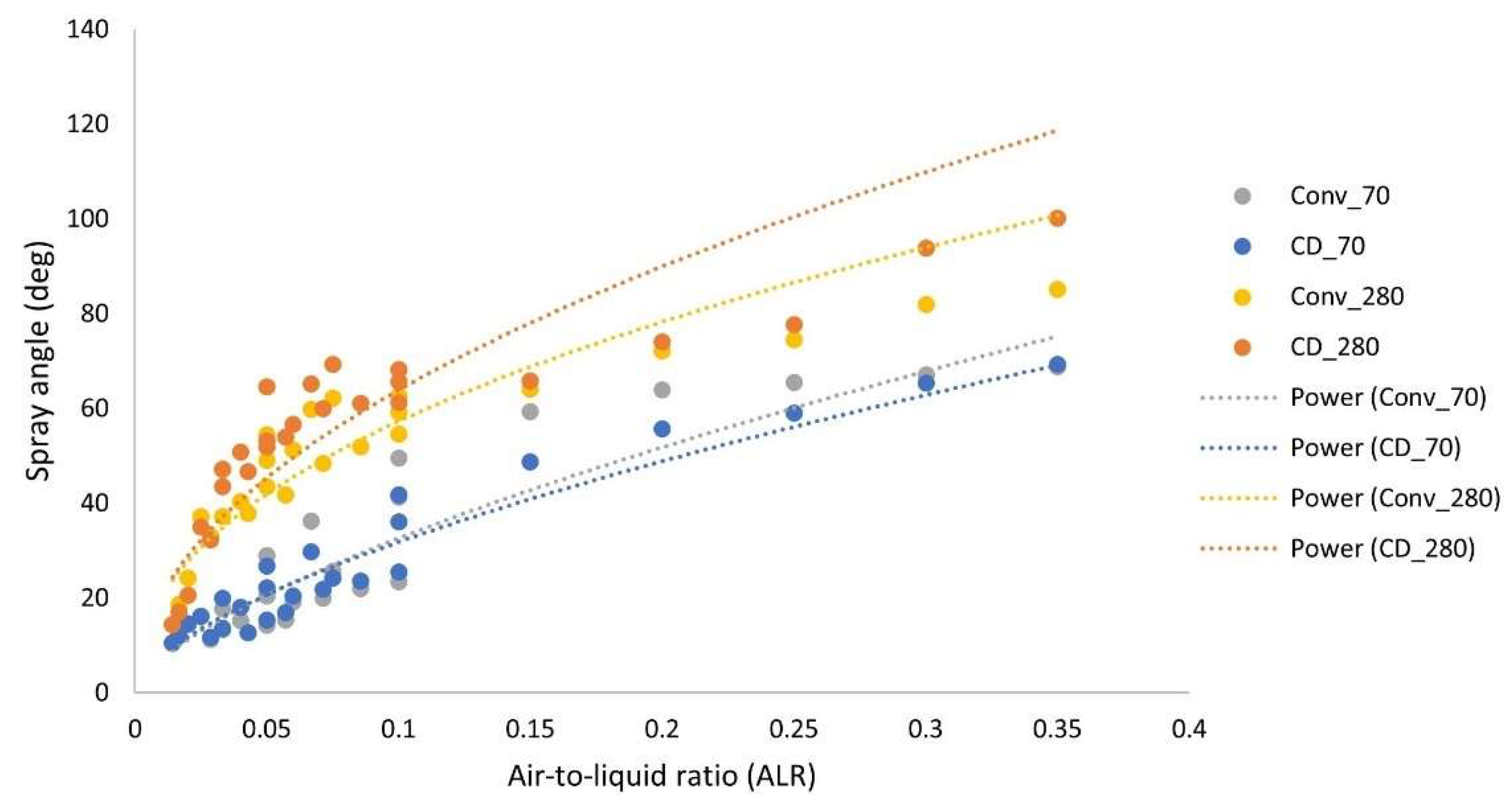
Different breakup patterns were observed for various flow rates such that, at low flow rates, the Rayleigh bubble regime (Figure 7a) was found with a certain bubble formation frequency at a given airflow rate with a slight increase in airflow rates.
As observed in [5], the bubble breakup regime was visualized, forming ligaments and large globular droplets downstream. With the further increase in air mass flow rates or ALR, the aerodynamic interaction increases, leading to corrugated/wavy sheet contraction, forming a neck region where the bursting phenomenon was identified. This bursting occurs near the nozzle exit region, forming the annular sheet disintegration regime (Figure 7b). With the further increase in ALR, the ligaments/filaments shed directly from the near-nozzle region because of the very high-speed interaction that led to a ligament-type breakup regime (Figure 7c). As we increase the liquid flow rates at a low ALR, the jet formation (Figure 7d) occurs with some waviness. For a 350 kg/h liquid flow rate, the wavy sheet was formed near the nozzle with a further airflow rate, which is contracted to form a wavy sheet disintegration (Figure 7e), leading to ligaments interconnected in a three-dimensional fashion and satellite drops downstream. At high flow rates (ALR), ligaments shed from all azimuthal angles of the annular sheet neck region, forming a christmas-tree regime. Finally, at very high air–liquid flow rates (high ALR), a pure-pulsating regime (Figure 7f) is observed, almost like the ‘Christmas tree breakup’ observed in [9], in which ligament-like structures pulsate alternatively on the left and right side of the spray centerline.
The breakup modes or regime diagram for converging and converging–diverging (CD) atomizers are similar, with a slight variation in the ALR range for different regimes. The regime diagram (see Figure 8) in a 3D manner with each axis corresponding to non-dimensional numbers is shown below.
The converging nozzle atomizer case for 280 µm sheet thickness is plotted based on the air-to-liquid ratio (ALR) defined in Equation (2), along with the non-dimensional numbers such as Reynolds number (Reg) based on gas flow in Equation (3), and Weber number (Wel) based on the liquid sheet in Equation (4), respectively, assuming the dynamic viscosity of air to be a relatively constant value of 18 µPa·s at 15 °C.
A L R = m a i r / m l i q u i d
Reg = ρg · ug · d/µg
WeL = ρL · uL2 · t/σL
where L = liquid, g = air, d = orifice (throat) diameter, and t = sheet thickness.

3.2.2. Spray Angle

The spray angle variation was observed for a change in fluid flow rates. Spray angle measurement is based on the tangent lines fitted at the spray edges at some downstream location, but the spray periphery is curved owing to air-interaction effects. In our case, spray angle was measured such that it covers the majority (approximately 99%) of the droplet mass of the whole spray, as is depicted (see Figure 9a,b). The set of 25 images (frames) were pre-processed (sharpness and contrast enhancement) in the ImageJ software for each data set before the angle measurements were taken. The angles were obtained by taking the mean (average) value of these 25 images, with an uncertainty of 2–3% due to observation error as the spray boundary line is vague. The spray boundary is more unclear in the case of sprays at higher ALR values, which can be attributed to the high density of the spray, which makes it more difficult to detect the spray edge [23]. The intensity-averaged images (Figure 9c,d) were not taken for measurement as they underpredict the spray angle for most cases.
The spray angle was plotted (Figure 10) against airflow rates for both 70 µm sheet thickness and 280 µm sheet thickness for the converging and CD atomizer, respectively. For the thin sheet (70 µm), as shown in Figure 10a, the spray angle rapidly increases with an increase in airflow, especially for low flow rates (say, 100 kg/h); the spray angle is relatively smaller for higher flow rates (say, 350 kg/h) owing to the higher axial momentum. The spray angle increased with an increase in the air flow rate; the increment is more continuous with a thicker sheet (280 µm) than with the thin sheet (70 µm) because of the lower axial momentum in the former sheet case. The increment is slightly more in the CD atomizer case than the converging atomizer (Figure 10b) for the higher liquid flow rate owing to the pulsating airflow, resulting in the more pronounced bursting phenomenon.
The spray angle against the air-to-liquid ratio was plotted for both converging and CD atomizers, for both sheet thicknesses (70 µm and 280 µm), in Figure 11. The spray angle increases with an increase in ALR values for all cases. For the 70 µm sheet, the spray angle is slightly higher for the converging atomizer than for the CD atomizer case, though the difference is apparent at relatively higher air-to-liquid ratios. In contrast, the spray angle is higher for the converging–diverging (CD) atomizer than the converging atomizer for the 280 µm sheet owing to the high contact strength, ejecting the sheet ligaments/parcels in a more pronounced fashion, resulting in the spreading of the spray periphery. The spray angle increment is more evident for higher airflow rates (high ALR).

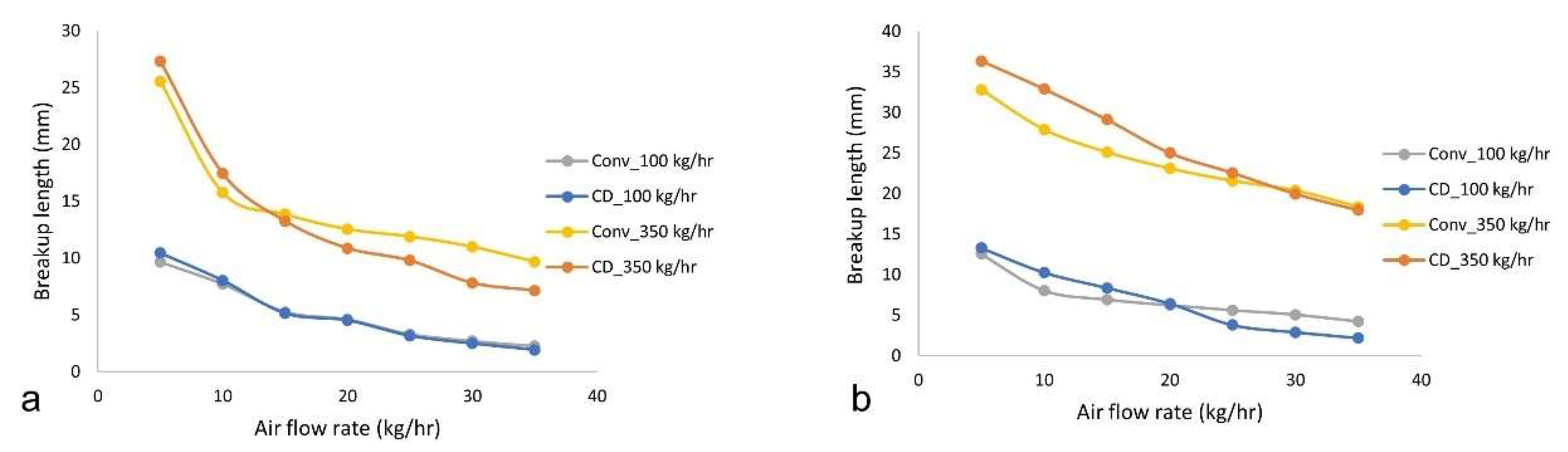
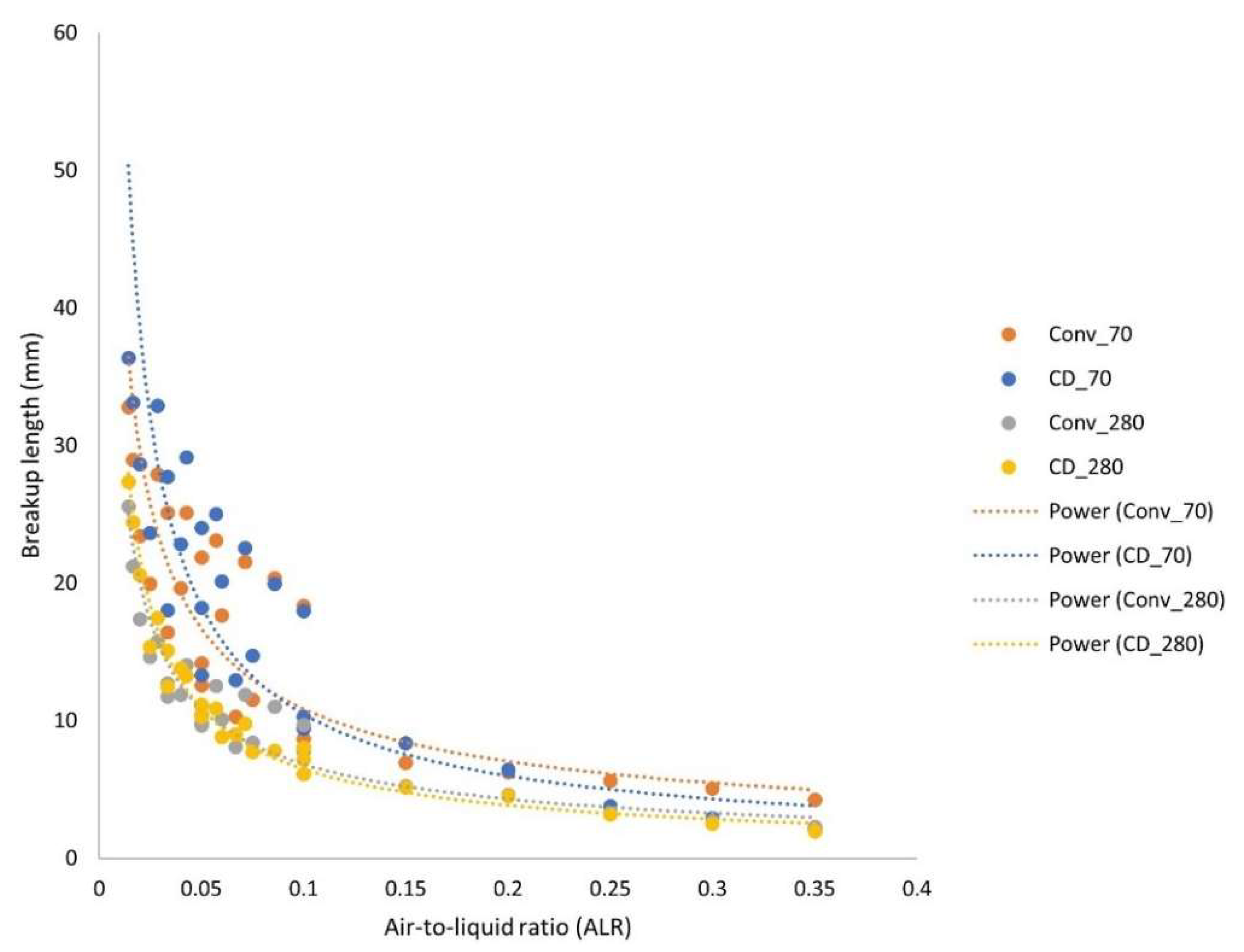
3.2.3. Breakup Length

The distance up to which the sheet is roughly intact is considered as the breakup length. The breakup length is measured using ImageJ software [24], such that intensity values (grayscale values: 255 = white, 0 = black) suddenly jump, as shown in Figure 12. The pixel location was traced for a stack of 25 images (averaged) where there is discontinuity, then this location where breakage occurs is converted into a distance value by calibrating the pixel in terms of distance (mm). In this case, the 66-pixel distance is the actual breakup length, converted into the mm scale based on the nozzle diameter (mm) in pixels. This method is adopted for low flow rates where raw images after being contrast-enhanced and brightened are stacked into full intensity-based or standard deviation images (see Figure 13) using Z-projection. This method provides a greater depth of field image than source images, highlighting our breakup location. For higher flow rates, the breakup location is taken as where the neck-formation region starts to disrupt. It is also measured for a stack of 25 images, which gives us a breakup length with an uncertainty of 1–2% due to observation or measurement error.
The breakup length has an inverse relation with the airflow rate, as shown in Figure 14; the breakup length has a more significant value for the higher liquid flow rate (350 kg/h), which converges to the same value for both types of atomizers with the increment in airflow rate for 70 µm sheet thickness (Figure 14a). The CD atomizer shows reduced breakup length, especially at higher airflow rates (35 kg/h). The breakup length follows a similar pattern for the 280 µm sheet thickness (Figure 14b). The breakup length reduces quite rapidly for higher water flow rates (350 kg/h) with an increase in airflow rates. The CD atomizer shows a greater decline in breakup length for higher liquid flow rates at a significant airflow rate. In contrast, the breakup length values converge for both types of atomizers for a lower liquid flow rate (100 kg/h) with increased airflow rates.
The breakup length was plotted (Figure 15) against airflow rates for both 70 µm sheet thickness and 280 µm sheet thickness for the converging and CD atomizer, respectively. The breakup length follows an inverse relationship with the air-to-liquid ratio (ALR). For the thin sheet (70 µm), the breakup length for the converging–diverging (CD) atomizer is lower than for the converging atomizer, which might be because of the sheet dragging effect due to the higher contact strength of air-jet ejecting from the former case, especially at a higher air-to-liquid ratio (ALR), whereas at lower ALR values, the breakup length for the converging–diverging (CD) atomizer is higher than for the converging atomizer, which is the condition before the flow is choked at the atomizer throat (atomizer exit in the case of the converging atomizer). Meanwhile, in the case of 280 µm sheet thickness, the breakup length for the converging–diverging (CD) atomizer is slightly lower than for the converging atomizer, which can be attributed to the sheet contraction (owing to surface tension) occurring with both atomizers for all ranges of fluid flow rates.

4. Discussion

In this study, the breakup dynamics of the annular sheet in a twin-fluid atomizer was investigated to probe the primary atomization behaviour of sonic/transonic atomizers. Two distinct atomizer configurations (converging and converging–diverging (CD)) were tested for the range of operating conditions in terms of air and liquid flow rates. The gas flow study showed the wave patterns for different airflow rates or total pressure (Pt). The irregular pressure distribution pattern along the visualized shock cells can lead to sudden acceleration or deceleration of the surrounding liquid sheet/ligament, which provides the sheet bursting effect. In the twin-fluid breakup study, the pressure distribution effect on the contracted sheet (due to the surface tension effect) dictates the breakup mechanics in the purview of the spray angle, breakup length, and so on. The bursting phenomenon (at the neck region) effect was observed in both kinds of atomizers, which can lead to the radial dispersion of the ligaments/globules, contributing substantially to the spray characteristics such as spray angle and so on. The breakup morphology was categorized into various observed breakup regimes: annular sheet disintegration, ligament type breakup, wavy sheet breakup, and pure-pulsating breakup. The air-to-liquid ratio (ALR) along with the liquid sheet Weber number (Weg) and Reynolds number (Rel) based on airflow are major parameters employed in the construction of the 3D breakup regime chart. There is no clear distinction of the regimes according to the ALR values. There is a certain overlap of breakup modes for the range of fluid flow rates such that certain breakup regimes gradually transit into another breakup regime. The breakup dynamics was studied with spray characteristics such as breakup length and spray angle. For low liquid flow rates (100 kg/h), the spray angle values showed a similar range for both the 70 µm sheet and 280 µm sheet. For higher flow rates (350 kg/h), the spray angle was narrower for the 70 µm sheet than for the 280 µm sheet because of the larger liquid axial momentum; spray diverges more for the 280 µm sheet because of the relatively lower velocity of the sheet, resulting in a more intense aerodynamic interaction of the high-speed air jet with the liquid sheet. In general, the spray angle dictates the aerodynamic interaction of the liquid droplets with the surrounding air, which affects the droplet size distribution downstream. The breakup length is affected by the contact strength of the high-speed air jet, which drags the wavy (subjected to Kelvin–Helmholtz instability) liquid sheet leading to the perforations or holes, further leading to the detachment of the globules/ligaments. For 70 µm, owing to the higher sheet velocity (momentum) for the given flow rate, the breakup length is relatively larger than for the 280 µm sheet. The breakup length follows an inverse relationship with the ALR values for all the cases employed. The whole study has some limitations owing to the difficulty in the visualization of high-speed fluid flow rates. The in-depth visualization of the wave pattern (formed in the air jet only) interaction with the contracted wavy liquid sheet would give more insights into the instability and hydrodynamics of the sheet breakup. Further research is needed in other directions to quantitatively study the effect of converging and converging–diverging (CD) atomizer usage in terms of the droplet size pattern and drop size distribution (DSD) for various operating conditions employed in this spray.

5. Conclusions

The characteristics of an annular sheet-based atomizer spray were photographically analyzed using high-speed imaging to study the breakup dynamics for the distinct airflow mechanism—the converging and CD atomizers. Breakup modes were discerned in both the converging and CD atomizers with a sheet thickness of 280 µm. Various modes were obtained from canonical Rayleigh bubble formation at very low ALR values, the annular sheet disintegration, and the ligament-type breakup at very high ALR values. The jet formation occurs at high liquid flow rates, whereas wavy sheet disintegration occurs at some moderate ALR values when the sheet contracted to form inter-connected ligament-like structures convecting in 3D space. The higher flow rates result in the formation of the christmas-tree breakup pattern.
Furthermore, the pure-pulsating mode was observed with the ligaments convecting downstream axially in alternate left and right pulsation directions to the spray centerline, further increasing the airflow rate. The spray angle was also obtained using the ImageJ software-based analysis. The spray angle shows a declining pattern with the increase in water flow rates (due to increased axial momentum) for both 70 µm and 280 µm sheet thicknesses, whereas the spray angle increases monotonously with an increase in airflow rates, for both converging and CD atomizers, respectively, with 280 µm sheet thickness. The increment in spray angle is more in CD atomizers than in the converging atomizer at higher airflow rates because of the more pronounced bursting effect in the former case. The breakup length follows an inverse power law relationship with the air-to-liquid ratio (ALR).

Author Contributions

Conceptualization, R.S. and J.L.; Methodology, R.S. and J.L., Investigation, R.S.; Formal analysis, R.S., Resources, K.V. and D.B.; visualization, R.S. and J.L.; writing-original draft preparation R.S.; writing—review and editing J.L.; Supervision, K.V. and D.B.; project administration, K.V. and D.B.; funding acquisition, K.V. and D.B. All authors have read and agreed to the published version of the manuscript.

Funding

The financial support provided by the PhD scholarship program in process, energy, and automation engineering of the University of South-Eastern Norway is greatly acknowledged.

Data Availability Statement

If required, additional data will be provided.

Acknowledgments

The researchers would like to express gratitude for the financial aid received from Wärtsilä Moss AS for the necessary equipment for the experimental setup.

Conflicts of Interest

The authors declare that there is no conflict of interest.

References

  1. Leboucher, N.; Laporte, G.; Carreau, J.L. Effect of the inner gas jet on annular liquid sheet atomization. Proceeding of the 21st Annual Conference on Liquid Atomization and Spray Systems, Taiwan, China, 8–9 November 2007; pp. 1–5. [Google Scholar]
  2. Fu, H.; Li, X.; Prociw, L.A.; Hu, T.C.J. Experimental investigation on the breakup of annular liquid sheets in two co-flowing airstreams. Proceeding of the 1st International Energy Conversion Engineering Conference IECEC, Portsmouth, Virginia, 17–21 August 2003; pp. 1–11. [Google Scholar] [CrossRef]
  3. Leboucher, N.; Roger, F.; Carreau, J.L. Disintegration process of an annular liquid sheet assisted by coaxial gaseous coflow(S). At. Sprays 2010, 20, 847–862. [Google Scholar] [CrossRef]
  4. Kawano, S.; Hashimoto, H.; Togari, H.; Ihara, A.; Suzuki, T.; Harada, T. Deformation and breakup of an annular liquid sheet in a gas stream. At. Sprays 1997, 7, 359–374. [Google Scholar] [CrossRef]
  5. Choi, C.J. Disintegration of Annular Liquid Sheet with Core Air Flow-Mode Classification. Int. J. Fluid Mech. Res. 1997, 24, 399–406. [Google Scholar]
  6. Adzic, M.; Carvalho, I.S.; Heitor, M.V. Visualization of the disintegration of an annular liquid sheet in a coaxial air-blast injector at low atomizing air velocities. Opt. Diagn. Eng. 2001, 5, 27–38. [Google Scholar]
  7. Li, X.; Shen, J. Experiments on annular liquid jet breakup. At. Sprays 2001, 11, 557–573. [Google Scholar] [CrossRef]
  8. Berthoumieu, P.; Lavergne, G. Video Techniques Applied to the Characterization of Liquid Sheet Breakup. J. Vis. 2001, 4, 267–275. [Google Scholar] [CrossRef]
  9. Leboucher, N.; Roger, F.; Carreau, J.L. Characteristics of the spray produced by the atomization of an annular liquid sheet assisted by an inner gas jet. At. Sprays 2012, 22, 515–542. [Google Scholar] [CrossRef]
  10. Zhao, H.; Xu, J.L.; Wu, J.H.; Li, W.F.; Liu, H.F. Breakup morphology of annular liquid sheet with an inner round air stream. Chem. Eng. Sci. 2015, 137, 412–422. [Google Scholar] [CrossRef]
  11. Kulkarni, V.; Sivakumar, D.; Oommen, C.; Tharakan, T.J. Liquid sheet breakup in gas-centered swirl coaxial atomizers. J. Fluids Eng. Trans. ASME 2010, 132, 0113031–0113037. [Google Scholar] [CrossRef]
  12. Sivakumar, D.; Kulkarni, V. Regimes of spray formation in gas-centered swirl coaxial atomizers. Exp. Fluids 2011, 51, 587–596. [Google Scholar] [CrossRef]
  13. Kihm, K.D.; Chigier, N. Effect of Shock Waves on Liquid Atomization of a Two-Dimensional Airblast Atomizer. At. Sprays 1991, 1, 113–136. [Google Scholar] [CrossRef]
  14. Park, B.K.; Lee, J.S.; Kihm, K.D. Kihm Comparative study of twin-fluid atomization using sonic or supersonic gas jets. At. Sprays 1996, 6, 285–304. [Google Scholar] [CrossRef] [Green Version]
  15. Heck, U.; Fritsching, U.; Bauckhage, K. Gas flow effects on twin-fluid atomization of liquid metals. At. Sprays 2000, 10, 25–46. [Google Scholar] [CrossRef]
  16. Mates, S.P.; Settles, G.S. A study of liquid metal atomization using close-coupled nozzles, part 2: Atomization behavior. At. Sprays 2005, 15, 41–59. [Google Scholar] [CrossRef]
  17. Zapryagaev, V.; Kiselev, N.; Gubanov, D. Shock-wave structure of supersonic jet flows. Aerospace 2018, 5. [Google Scholar] [CrossRef] [Green Version]
  18. Liepmann, H.W.; Roshko, A. Elements of Gas Dynamics, 2001th ed.; Dover Publications: New York, NY, USA, 2001. [Google Scholar]
  19. Liu, A.B.; Reitz, R.D. Mechanisms of air-assisted liquid atomization. At. Sprays 1993, 3, 55–75. [Google Scholar] [CrossRef]
  20. Stapper, B.E.; Sowa, W.A.; Samuelsen, G.S. Stapper An Experimental Study of the Effects of Liquid Properties on the Breakup of a Two-Dimensional Liquid Sheet. J. Eng. Gas Turbines Power 1992, 114. [Google Scholar] [CrossRef]
  21. Lavergne, G.; Trichet, P.; Hebrard, P.; Biscos, Y. Liquid Sheet Disintegration and Atomization Process on a Simplified Airblast Atomizer. J. Eng. Gas Turbines Power 1993, 115, 461–466. [Google Scholar] [CrossRef]
  22. Issac, K.; Missoum, A.; Drallmeier, J.; Johnston, A. Atomization experiments in a coaxial coflowing Mach 1.5 flow. AIAA J. 1994, 32, 1640–1646. [Google Scholar] [CrossRef]
  23. Karnawat, J.; Kushari, A. Spray evolution in a twin-fluid swirl atomizer. At. Sprays 2008, 18, 449–470. [Google Scholar] [CrossRef]
  24. Schneider, C.A.; Rasband, W.S.; Eliceiri, K.W. NIH Image to ImageJ: 25 years of image analysis. Nat. Methods 2012, 9, 671–675. [Google Scholar] [CrossRef] [PubMed]
Figure 1. Experimental sonic atomizer: (a) atomizer body with cap, (b) assembled atomizer, and (c) nozzle schematic depicting core air and annular liquid flow.
Applsci 11 10444 g001
Figure 2. Schematic of the shadowgraph setup for the gas flow study (in-flow).
Applsci 11 10444 g002
Figure 3. Schematic of the experimental setup for sheet breakup (in-flow).
Applsci 11 10444 g003
Figure 4. Wave pattern observed in shadowgraph imaging at 20,000 frames per second for the (a) converging nozzle and (b) CD nozzle at 35 kg/h airflow rate.
Applsci 11 10444 g004
Figure 5. For the converging atomizer with 70 µm (top row) and 280 µm (bottom row) sheet thickness at a 100 kg/h water flow rate with airflow rates of (a,e) 5 kg/h, (b,f) 15 kg/h, (c,g) 25 kg/h, and (d,h) 35 Kg/h, respectively.
Applsci 11 10444 g005
Figure 6. For the converging–diverging (CD) atomizer at 100 kg/h (top row) and 350 kg/h water flow rates for 280 µm sheet thickness with airflow rates of (a,e) 5 kg/h, (b,f) 15 kg/h, (c,g) 25 kg/h, and (d,h) 35 Kg/h, respectively.
Applsci 11 10444 g006
Figure 7. For the converging nozzle with 280 µm sheet thickness at a 100 kg/h water flow rate (Top row) and at a 350 kg/h water flow rate (Bottom row), respectively, with airflow rates of (a,d) 1 kg/h, (b,e) 10 kg/h, and (c,f) 35 Kg/h, respectively.
Applsci 11 10444 g007
Figure 8. Regime chart for the converging atomizer for various flow rates for 280 µm sheet thickness.
Applsci 11 10444 g008
Figure 9. Spray angle measurement for the CD nozzle atomizer for two cases: (a,c) water and an airflow rate of 100 kg/h and 5 kg/h, respectively; (b,d) water and an airflow rate of 350 kg/h and 35 kg/h, respectively.
Applsci 11 10444 g009
Figure 10. Spray angle measurement for both the converging and converging–diverging (CD) atomizer case with 70 and 280 µm sheet thickness.
Applsci 11 10444 g010
Figure 11. Spray angle measurement variation with ALR for the converging and converging–diverging (CD) atomizer cases with 70 and 280 µm sheet thickness.
Applsci 11 10444 g011
Figure 12. Breakup length measurement: (a) contrast-enhanced raw image, (b) maximum intensity (averaged) image, and (c) profile of grayscale values along the centerline (yellow).
Applsci 11 10444 g012
Figure 13. Breakup length measurement with the 280 µm sheet with a water and airflow rate of 100 kg/h and 20 kg/h, respectively, (a,c) for the converging atomizer and (b,d) for the converging–diverging (CD) atomizer.
Applsci 11 10444 g013
Figure 14. Breakup length measurement for both the converging and CD atomizer for two cases: (a) 70 µm sheet thickness and (b) 280 µm sheet thickness.
Applsci 11 10444 g014
Figure 15. Breakup length measurement variation with ALR for converging and CD atomizer cases with 70 and 280 µm sheet thickness.
Applsci 11 10444 g015
Table 1. The range of operating conditions and representative dimensionless numbers.
QuantityRange
Airflow rate 15–35
Water flow rate 1100–350
Air-to-liquid ratio (ALR)0.014–0.35
Liquid Weber number (Wel)17.2–844.9
Air Reynolds number (Reg)33,000–229,000
1 in kg/h.
Publisher’s Note: MDPI stays neutral with regard to jurisdictional claims in published maps and institutional affiliations.

