Here, for the storage system under investigation commercially available products suitable for this application were used. These include an Al
2O
3 ceramic as solid for the honeycomb structure [
32], a ferritic FeCrAl alloy [
33] for the heating wire and a microporous material [
34] for the thermal insulation. Central temperature-averaged material properties are summarized in
Table 1 for the considered operational range.
For a well-founded evaluation of the storage system, a detailed detection of the heat transport mechanisms is needed. This is done using the effective radiation coefficient
krad, which considers the heat transport by radiation and conduction within the overall model in a compact way. Results on this including a novel formulation are presented in
Section 3.1. Subsequently, in
Section 3.2, systematic investigations for the storage system on the basis of application-typical specifications are performed, depending on the relevant geometric variables. Central contexts to systemic storage densities and heating wire dimensions are explained and storage-optimized results including the selection of a first favored concept are presented.
Mesh studies relating to the averaged honeycomb temperatures were performed in order to reach a high accuracy of the simulation. The investigations showed that with maximum permitted deviations of less than 10−4 an axial discretization of at least 60 nodes and a radial discretization of at least 30 nodes are required for both simulation models.
3.1. Effective Radiation Coefficient
For investigation of the electrically heated storage system, a detailed detection of the heat transport mechanisms inside the effective radiation coefficient
krad is necessary, requiring a geometry-, process- and material-based parametrization. Extensive simulation studies (
Table 2) on the relevant influencing factors were performed and
krad was iteratively determined by minimizing the temperature deviations between the porosity based and the detailed based model. The variations include the solid mass (
mS), the length to diameter ratio (
L/D), the specific surface (
aV) and the void fraction (ε) of the honeycomb structure as well as the heating wire assignment (
x), its diameter (
dP) and the charging duration (τ). Here, the heating wire temperature (
TP) was set constant at a maximum permitted value of 1000 °C.
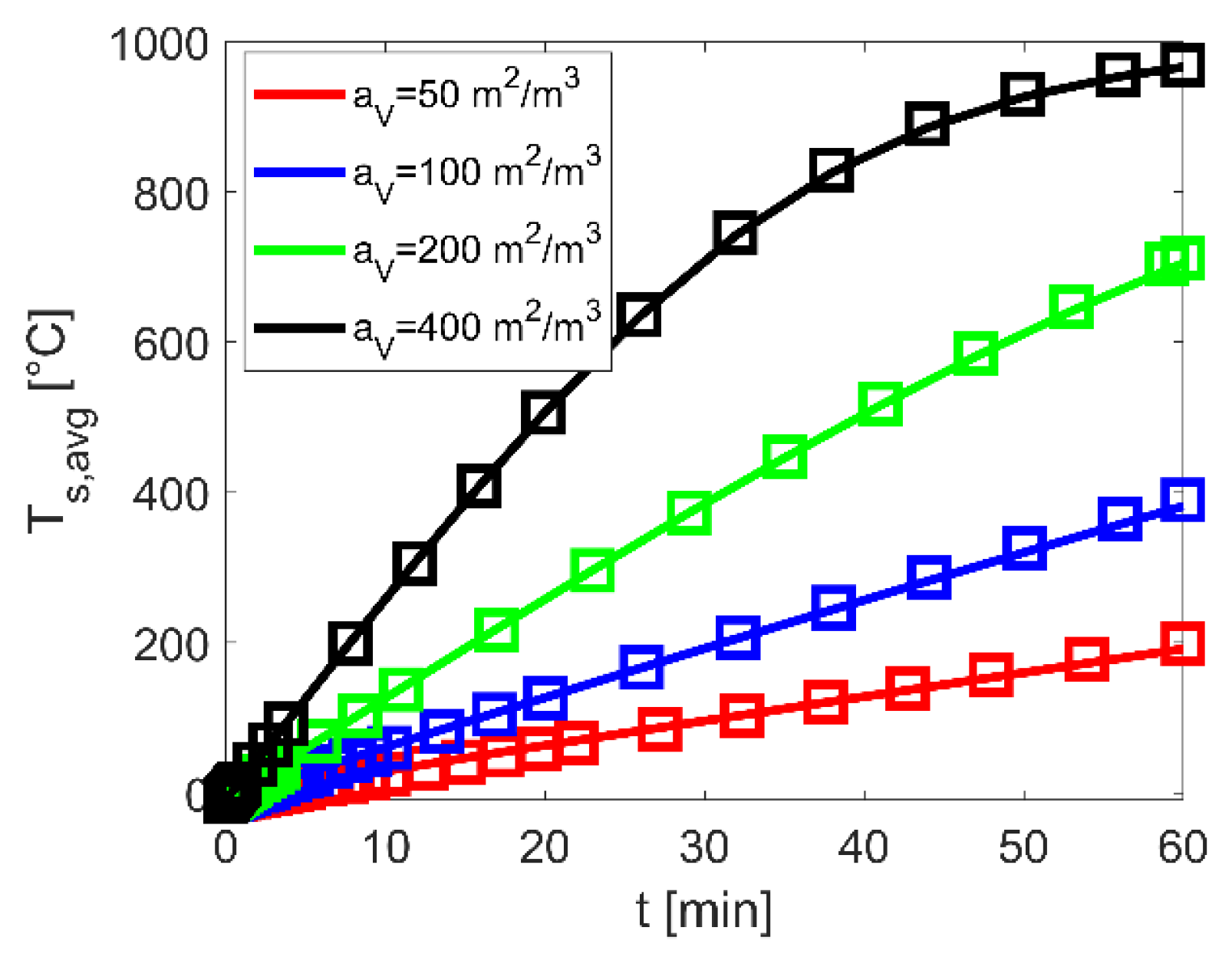
For an exemplary case,
Figure 3 shows the resulting temporal temperature characteristics for four specific surfaces of the honeycomb structure. The squares represent the results based on the detailed model with the pure radiation coefficients
Crad and local thermal conduction, the solid lines the results based on the porosity model with the iteratively determined effective radiation coefficients
krad. In addition, the corresponding coefficients
Crad and
krad are summarized in
Table 3.
The results show with increasing specific surfaces significant higher temporal temperature characteristics as well as rapprochements between the iteratively determined radiation coefficients
krad to the pure radiation coefficient
Crad (
Table 3). These results are associated with an increasing heat transport due to two central effects: a total higher number of honeycomb channels with heating wires and decreasing wall thicknesses of the honeycomb structure, thus negligible thermal conduction resistances. Comparable characteristics of different magnitude are also evident in other results within the variation matrix. Additionally, a good agreement in the temporal heating characteristic between the detailed and the porosity model with maximum deviations of lower 5% are reached.
Due to the large number of geometric, process and material configurations, a parameterization of
krad is needed in order to enable a computationally efficient and detailed investigation of the electrically heated storage system throughout the porosity model. For this purpose, an approach based on the Fourier number (
Fo) according to Equation (21) is assumed
whereby the characteristic length
lc as defined in Equation (22) represents through its novel formulation all relevant geometric aspects of such a storage system
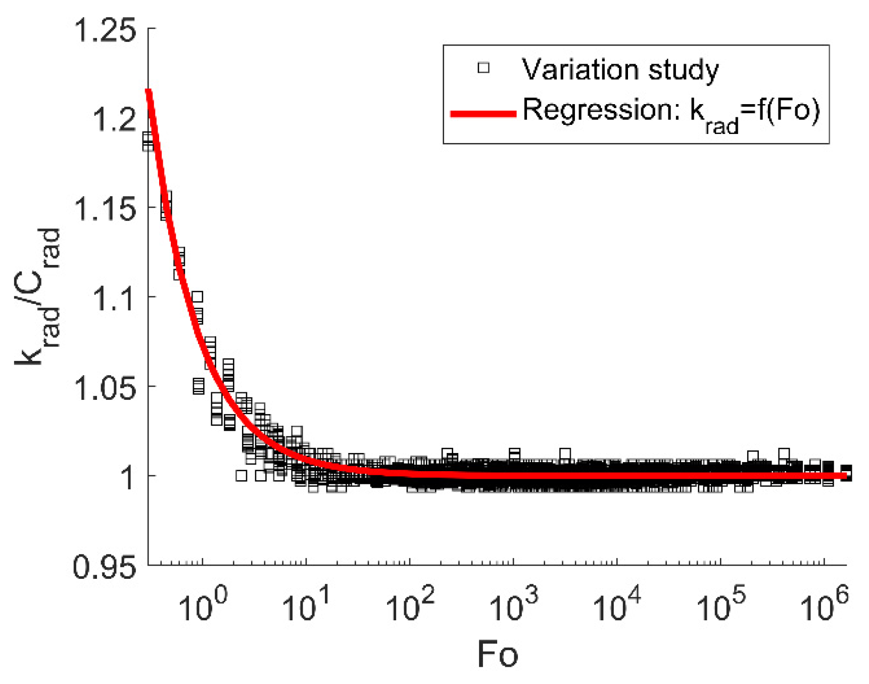
The Fourier number as well as the characteristic length defined in this way include all relevant geometric-, process- and material-relating aspects of the honeycomb structure with integrated heating wires. With this dimensionless quantity a comparison between the iteratively determined effective radiation coefficient
krad to the pure radiation coefficient
Crad are conducted. Results based on the variation matrix from
Table 2 are shown in
Figure 4.
The resulting ratios show clearly a correlation between the effective to pure radiation coefficients and pointed out the usability of the novel formulation regarding the characteristic length inside the Fourier number. As can be seen at Fourier numbers > 102 the heat transport is dominated by thermal radiation without influence of thermal conduction within the honeycomb structure. However, for lower Fourier numbers higher iteratively determined effective radiation coefficients krad are resulting compared to the pure radiation coefficient Crad. This is due to the fact, that the heat transport in the porosity model refers to a homogeneous honeycomb temperature, whereas the detailed model calculates the geometry-resolved temperature distributions in the honeycomb structure and thus captures effects of local thermal resistances. Within the porosity model, this leads especially for thick-walled honeycomb structures or configurations with low heating wire assignments to an underestimation of the heat transport only on the basis of the pure radiation coefficient Crad resulting in higher krad/Crad ratios at Fo < 102.
Based on the presented results, it is obvious that a detailed capture of the heat transport mechanisms is achieved by the effective radiation coefficient
krad. For implementation inside the porosity model, a power law approach according to Equation (23) is used
which allows through its parameterized formulation via the Fourier number a wide consideration of different configurations.
This novel correlation regarding the effective heat transport opens up time-efficient calculations for such electrical heated honeycomb structures without losing accuracy. Therefore, only the pure radiations coefficient must be determined and adapted according Equations (22) and (23) towards the investigated honeycomb-heating-wire configuration.
3.2. Thermal Storage System
Based on the models described in
Section 2.1 and the parameterized formulation of the effective radiation coefficient according to
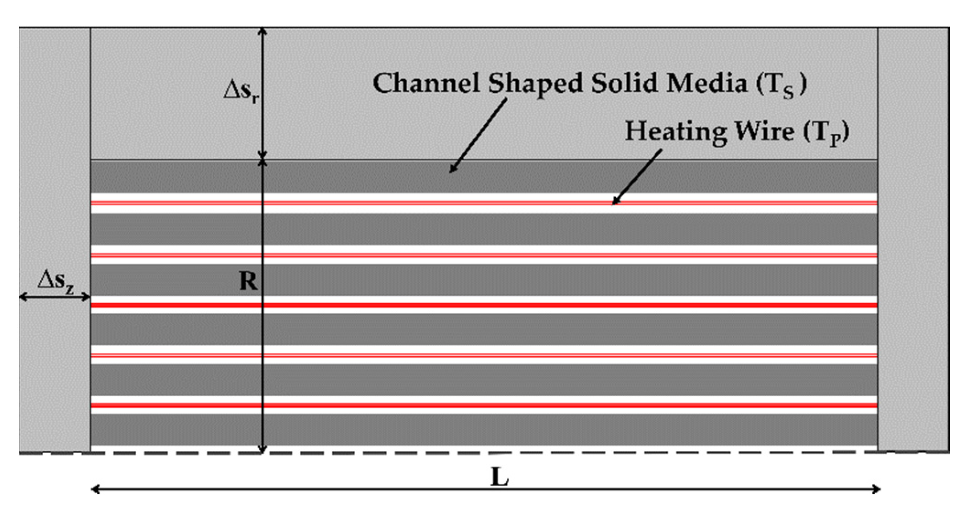
Section 3.1, systematic investigations of the storage system are performed. Overall aim is to identify storage system configuration with high systemic storage densities complying at the same time restrictions regarding the maximum permitted surface temperature (
TW). For this, the maximum thermal insulation thicknesses required to maintain the permitted surface temperature at the frontal areas (Δ
sZ) and at the shell surface (Δ
sr) of the honeycomb structure were iteratively calculated for each design solution. Hereby the extreme case–homogeneously heated honeycomb at the maximum operating heating wire temperature
TP,max–was assumed.
Application-typical specifications for the storage system with regard to charging duration (τ), storage capacity (
Q), maximum permitted surface temperature (
TW) and electrical power supply (
U,
Imax) are defined and summarized in
Table 4.
Here, values of 1000 °C and −10 °C were specified for the maximum permitted heating wire temperature (
TP,max) and for the ambient temperature (
TU). The material properties of the heating wire, the honeycomb structure and the thermal insulation were assumed to be constant and can be found in
Table 1.
In order to examine the storage system for its performance and systemic storage densities, variation studies were performed on the relevant influencing variables. These include the heating wire assignment (
x), the specific surface (
aV) and the void fraction (ε). Hereby, the minimum storage mass (
mS) of the honeycomb structure was iteratively determined for each design solution fulfilling the required specifications as shown in
Table 4. Due to neglectable influences of the length-to-diameter ratio on the results within the simulation studies a constant value of
L/
D = 2 was set.
For explanation of the central effects with regard to systemic storage density and heating wire dimensions, results on specific surface and heating wire assignment are presented firstly in
Section 3.2.1. Based on these, storage-optimized results are derived in
Section 3.2.2 and the impact of void fractions are discussed. Finally, central characteristics of the transient heating process for a favored design option and the resulting storage dimensions are presented in
Section 3.2.3.
3.2.1. Fundamental Contexts to Systemic Storage Densities
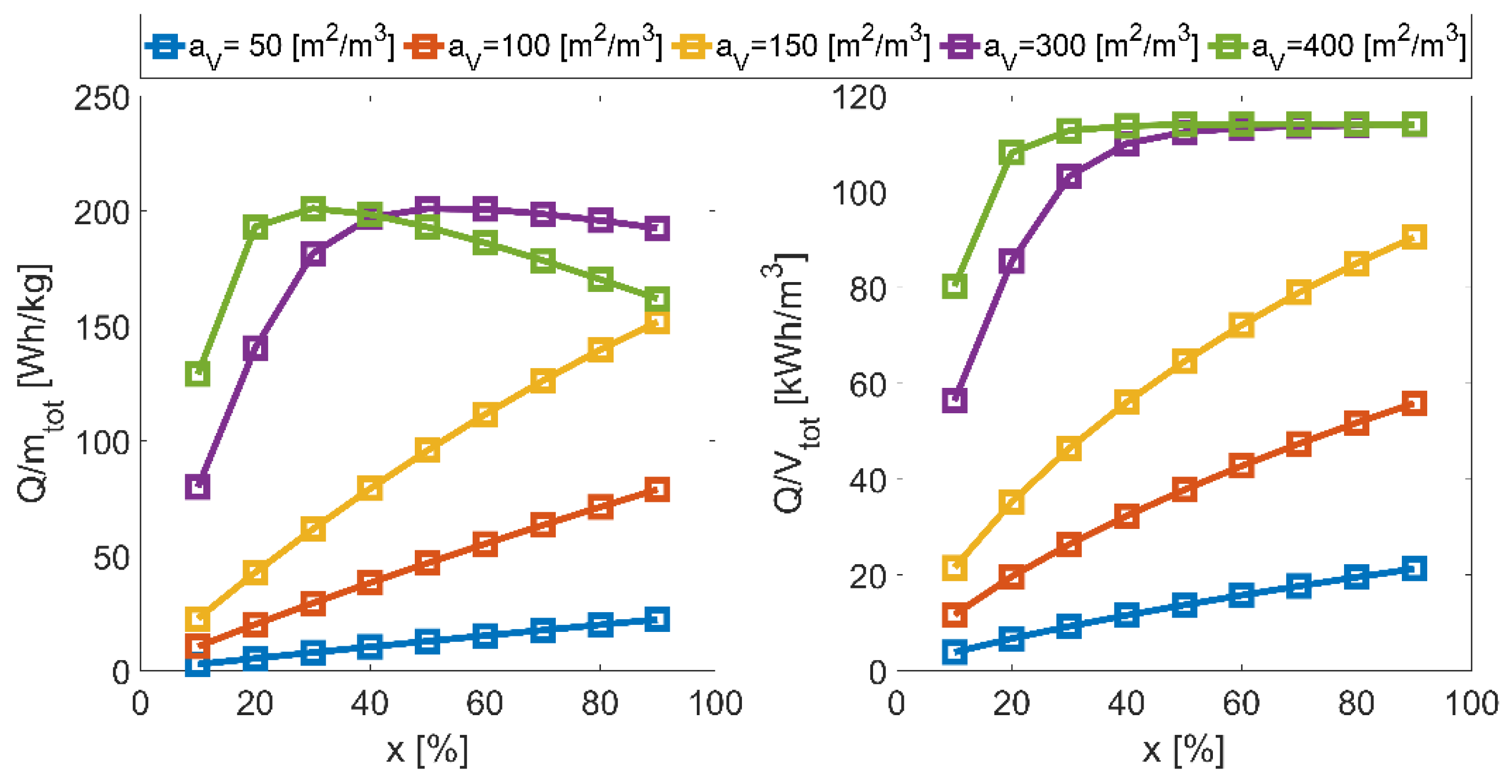
For investigating of such a concept on its systemic storage densities, results depending on the heating wire assignment and the specific surface for an exemplary selected solution set with a void fraction of 42.5% are shown in
Figure 5. Hereby the gravimetric systemic storage density (
Q/
mtot) includes the mass of the honeycomb, the heating wire and the thermal insulation and the volumetric systemic storage density (
Q/
Vtot) includes the volume of the honeycomb and the thermal insulation.
The results show an increase in systemic storage densities up to a maximum value with increasing heating wire assignments at constant specific surfaces. This is due to the fact, that with this associated higher storage temperatures allow decreasing honeycomb masses or volumes, but increase simultaneously the heating wire and thermal insulation dimensions. Specifically, for efficient design solutions with high specific surfaces and hence the lowest honeycomb dimensions, this contrary effect leads to the observed maximum in gravimetric and the plateau in volumetric systemic storage density.
The lower systemic storage densities with decreasing specific surfaces at constant heating wire assignments results from their corresponding smaller number of honeycomb channels. This leads–apart from increasing thermal conduction resistances–to shorter total heating wire lengths (LP) and so to a moderate heating of the honeycomb structure and thus to higher storage masses.
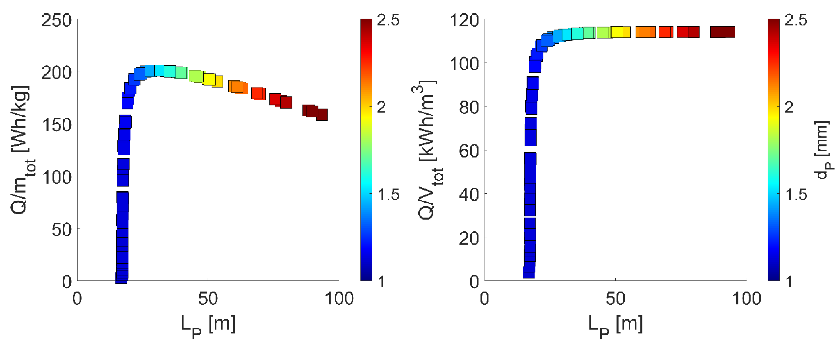
This context is illustrated in
Figure 6 showing the systemic storage densities as a function of the resulting heating wire dimensions.
The results show a direct correlation between the systemic storage densities and the heating wire dimensions. With increasing heating wire length, a maximum value in the systemic storage densities is reached limited by above-described contrary effect between honeycomb and heating wire or thermal insulation dimensions. Optimal solutions–here with heating wire length of about 30 m–can be directly derived from configurations with appropriate specific surfaces and heating wire assignments. Additionally, the results show correlating heating wire lengths to heating wire diameters (
dP) as illustrated in colored dots. This behavior is based on the specified electrical power supply in
Table 4 forcing a constant electrical resistance and thus increasing heating wire diameters with heating wire lengths.
For the results presented here with an exemplary selected void fraction, maximum gravimetric and volumetric systemic storage densities of about 201 Wh/kg and 113 kWh/m3 are reached, whereby these are associated with design solutions for specific surfaces and heating wire assignments. In order to identify only such systems with maximum possible storage densities, iterative optimization simulation studies were performed. The corresponding results with this as well as the influence of void fraction are presented in the following.
3.2.2. Optimized Systems with Maximum Gravimetric Storage Density
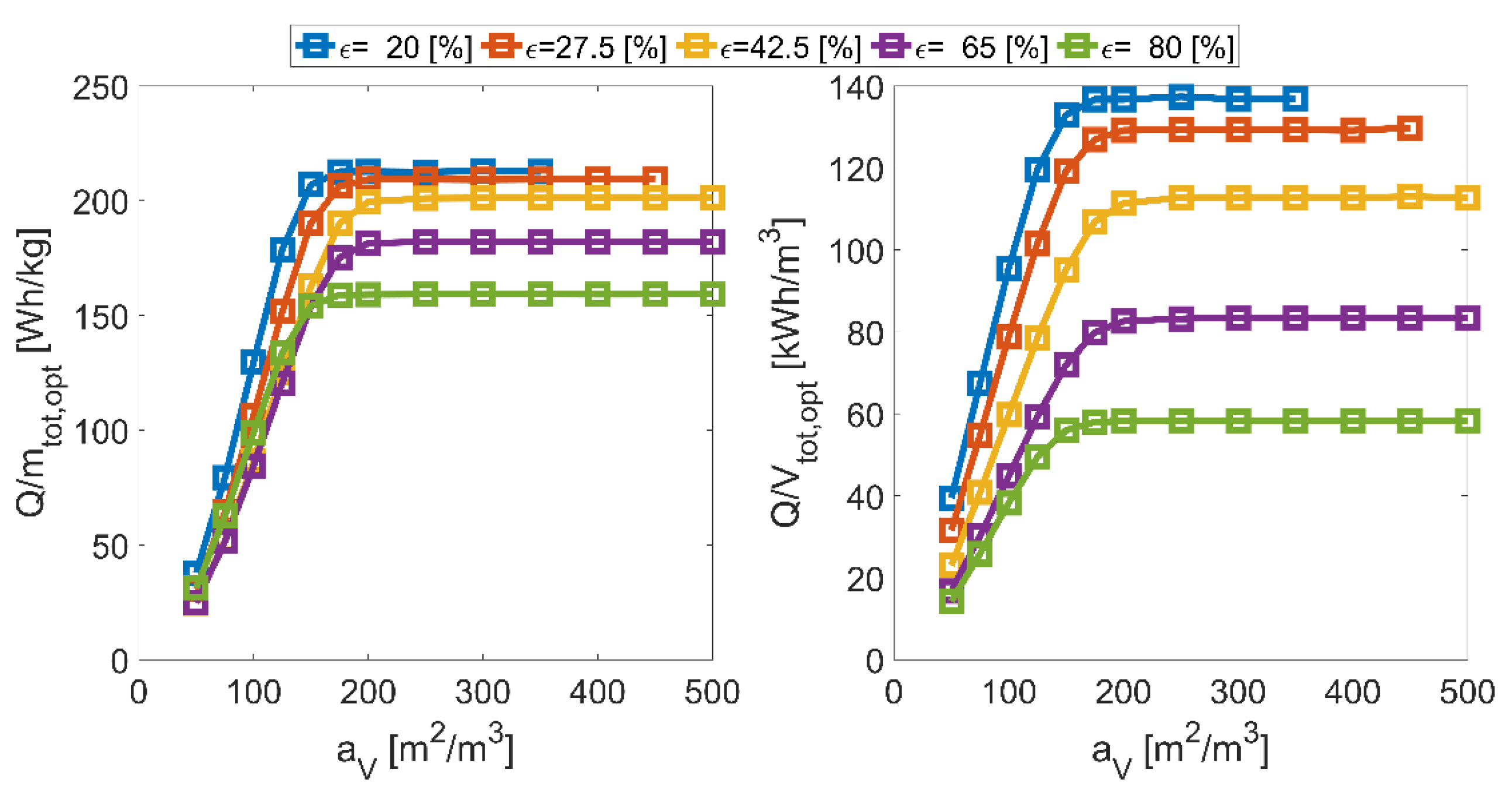
As explained in
Section 3.2.1, maximum possible storage densities are reached based on appropriate configurations regarding the specific surface and the heating wire assignment, whereby the void fraction (ε) was kept constant so far. For a holistic investigation of the storage system, additional variation studies are performed on this. Hereby, the presented results refer to the maximum possible gravimetric storage densities determined through iterative optimization simulations to the heating wire assignment depending on the specific surface. Central results regarding the iteratively optimized systemic storage densities are illustrated in
Figure 7.
The results show increasing maximum possible systemic storage densities with higher specific surfaces. This is caused by the already mentioned effect regarding the number of honeycomb channels, the corresponding heating wire lengths and thus only a moderate temperature elevation. For those solutions, the iteratively determined results force a maximum heating wire assignment of 100% to reach their maximum possible systemic storage densities. In contrast, at high specific surfaces of 500 m2/m3–thus a maximum temperature elevation of the honeycomb structure–only heating wire assignments of less than 20% are needed.
Additionally, the results point out that for maximum possible storage densities a specific surface of above 200 m2/m3 is required, whereby its magnitude only depends on the void fraction. But with higher void fractions increasing honeycomb and proportionally significantly increasing thermal insulation volumes are associated leading to reductions in systemic storage densities, especially for the volumetric. Furthermore, the results show an absence of solutions at high specific surfaces and small void fractions. This is caused by associated insufficient low channel diameter of the honeycombs compared to the heating wire diameter.
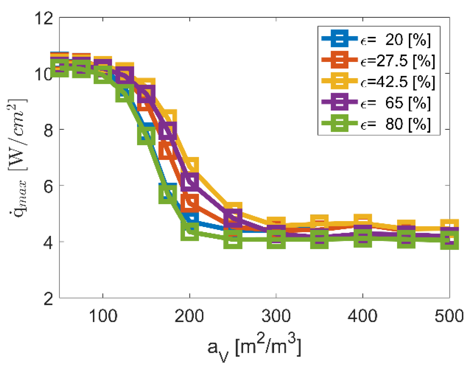
The presented results and contexts point out the significance of high specific surfaces as central prerequisite for maximum systemic storage densities. However, for a holistic evaluation of such systems, additional statements regarding the heating wire surface load (
) and thus the lifetime are necessary. Therefore, the maximum heating wire surface loads occurring in the transient process are shown in
Figure 8 based on the iteratively optimized variation studies.
The results show decreasing maximum heating wire surface loads with higher specific surfaces. This is due to the fact of increasing heating wire diameters and lengths with slight void fraction-related dependencies. However, it is visible that well-suited heating wire surface loads of less than 5 W/cm
2 [
35] are reached with sufficient high specific surfaces of more than 250 m
2/m
3 minimizing lifetime-critical conditions in addition to the already moderate heating wire temperature of 1000 °C.
Based on these results for optimized systemic storage densities and corresponding maximum heating wire surface loads, a favored design option is selected meeting also geometrical requirements in terms of specific surface and void fraction for an efficient thermal discharging operation with low pressure drops as describe in [
23]. For this, transient characteristics as well as central storage dimensions are presented in the following.
3.2.3. Selected Design Option: Temporal Characteristics and Dimensions
Within the wide solution spectrum, a favored design option was selected considering systemic storage densities, maximum heating wire surface loads and thermal discharging requirements. The selected solution is based on a honeycomb structure with a specific surface of 350 m
2/m
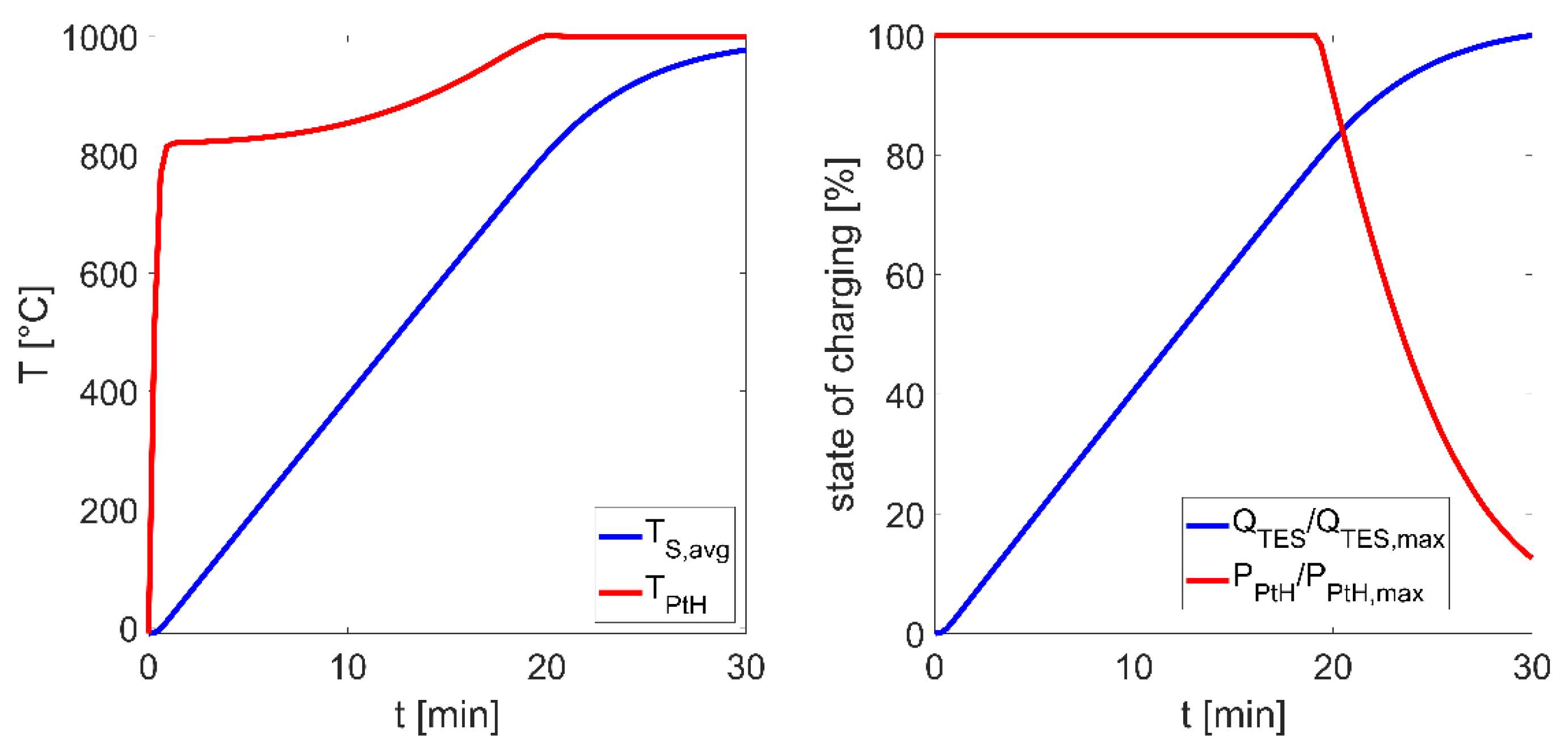
3, a void fraction of 42.5% and a heating wire assignment of 38.4%. Central transient characteristics are shown in
Figure 9.
As can be seen, a constant electrical heating power is achieved over a period of about 20 min, whereby a linear temperature elevation of the honeycomb structure from −10 °C to 800 °C or a thermal charging state of 80% is reached. From this point on, the implemented control algorithm leads to a reduction of the heating power to limit the heating wire temperature at 1000 °C. The heating wire itself shows significantly higher temperature gradients at the beginning of the loading process due to lower thermal masses compared to the honeycomb. However, from a heating wire temperature of about 800 °C the dominating radiation heat transport leads to substantial increasing honeycomb temperatures and thus to reduced heating wire temperature gradients.
For the exemplary favored design option presented here, systemic storage densities of 201 Wh/kg and 113 kWh/m
3 with a maximum heating power of 6.4 kW are reached. During charging maximum heating wire surface loads of 4.6 W/cm
2 occur at heating wire length and diameters of 30 m and 1.5 mm, respectively. Despite the high storage temperatures, only maximum heat losses of about 76 W occur resulting from the restrictive specification regarding the maximum permitted surface temperature of 60 °C (
Table 4) and the small storage dimensions. Central specifications of the selected design option are summarized in
Table 5.
The systematically prepared results regarding systemic storage densities and heating wire surface loads confirm the feasibility and efficiency of such storage systems for the heat supply in BEV. Comparable results are also reached for different electrical power supplies and for charging durations of less than 30 min.
The contexts presented here elucidate the need of high specific surfaces of solid media thermal energy storages in addition with adequate selected void fractions. Comparable geometric conditions are also required during thermal discharging, in order to allow efficient convective heat transport to the heat transfer medium (air). The associated thermodynamic synergies in the cyclic storage process, the achievable systemic storage densities and the commercial availability of such ceramic honeycomb structures confirm the potential of the technology as alternative thermal management concept of battery electric vehicles.
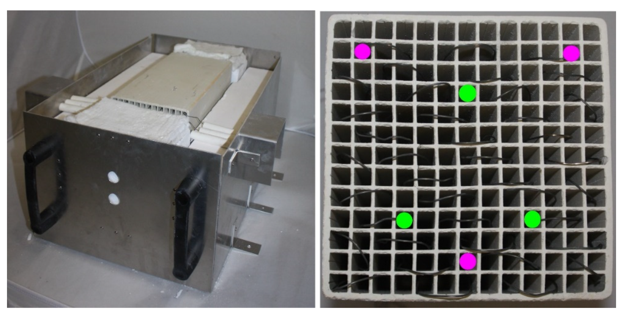
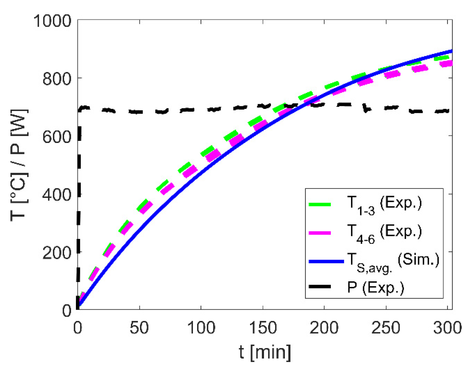
For proof of concept a test rig was erected, enabling due its high flexibility in terms of electrical voltage, heating power and exchangeable storage media wide experimental investigations. First results of an exemplarily honeycomb-heating-wire-configuration were performed and used for validation of the described porous simulation model.


