Article

Design and Implementation of Composed Position/Force Controllers for Object Manipulation

by
Sergio Hernandez-Mendez
1,*,
Elvia Ruth Palacios-Hernandez
2,
Antonio Marin-Hernandez
1,*,
Ericka Janet Rechy-Ramirez
1 and
Hector Vazquez-Leal
3
1
Artificial Intelligence Research Institute, Universidad Veracruzana, Calle Paseo No. 112, Colonia Nueva Xalapa, Xalapa 91097, Mexico
2
Faculty of Sciences, Universidad Autónoma de San Luis Potosí, Av. Chapultepec No. 1570, Priv. del Pedregal, San Luis Potosí 78295, Mexico
3
Electronic Instrumentation and Atmospheric Sciences School, Universidad Veracruzana, Cto. Aguirre Beltrán S/N, Zona Universitaria, Xalapa 91090, Mexico
*
Authors to whom correspondence should be addressed.
Appl. Sci. 2021, 11(21), 9827; https://doi.org/10.3390/app11219827
Submission received: 30 September 2021 / Revised: 15 October 2021 / Accepted: 16 October 2021 / Published: 21 October 2021
(This article belongs to the Special Issue Advances in Industrial Robotics and Intelligent Systems)

Abstract

:
In the design of a controller for grasping objects through a robotic manipulator, there are two key problems: to find the position of the object to be grasped accurately, and to apply the appropriate force to each finger to handle the object properly without causing undesirable movement of it during its manipulation. A proportional-integral-derivative (PID) controller is widely used to grasp objects in robotics; however, its main shortcomings are its sensitivity to controller gains, sluggish response, and high starting overshooting. This research presents three coupled (position/force) controllers for object manipulation using an assembled robotic manipulator (i.e., a gripper attached to a robotic arm mounted on a mobile robot). Specifically, an angular gripper was employed in this study, which was composed of two independent fingers with a piezoelectric force sensor attached to each fingertip. The main contributions of this study are the designs and implementations of three controllers: a classic PID controller, a type-I controller, and a type-II fuzzy controller. These three controllers were used to find an object to be grasped properly (position) and apply an equivalent force to each finger (force).

1. Introduction

Due to uncertainty on localization, mobile robot manipulation faces two key problems when trying to manipulate objects: firstly, computing the correct position at which the mobile robot needs to be for grasping an object, and secondly, calculating the specific position at which the object to be grasped is.
Specifically, object manipulation through a robotic arm involves three actions: (i) moving the robot and positioning it at a place where its arm’s configuration space intercepts the object’s position (Figure 1a); (ii) planning and execution of the arm’s trajectories—that is, to move the robotic arm towards a position where the object is inside the gripper’s configuration space, i.e., where the gripper (end effector) may grasp the object [1,2] (Figure 1b); and (iii) tuning the gripping action—i.e., closing the gripper in order to take and manipulate the object properly [3,4,5] (Figure 1c). The first two actions are called the pre-grasping stage, and the last action is named the grasping stage.
The gripper and their controller are key components at the grasping stage in order to manipulate objects accurately. Parallel motion grippers and angular motion grippers are the most commonly used in robotics for object manipulation [6]. Parallel grippers usually have only one motor; therefore, their fingers move simultaneously in order to handle objects. Recently, the use of grippers with angular motions has increased. Thanks to their configuration, these grippers extend the gripping range of objects, and different configurations may be calculated to handle an object; therefore, these grippers might provide dexterous object manipulation similarly to human fingers. Detailed reviews regarding several types of grippers can be found in [7,8,9].
Focusing on controllers, the PID controller has been widely used in control systems [10,11,12,13] due to its simplicity and robustness. In the last few years, there has been increasing interest in using fuzzy logic in different control systems [14,15,16,17,18,19,20]. Moreover, fuzzy logic has been used for implementing several applications. For instance: in a multicriteria decision-making process [21], energy consumption for bipedal walking robots [22], and search engine systems [23]. Fuzzy logic uses fuzzy values and rules to cope with uncertainty, just as humans do. These fuzzy values and rules may be implemented based on the user’s experience instead of using complex mathematical models.
In the present work, an angular gripper with two independent fingers was used. Prior to the manipulation stage, the actions described in Figure 1 were done. The object’s position, initially unknown, was obtained by a perception system and was used to bring the arm close to the object. However, at this stage of the work, no visual surveying has been used. Instead, a tactile feedback control is performed. The object’s dimensions were used to estimate the gripper’s initial opening. Once the object was between gripper fingers, angular position and (when object do contact) pressure forces were used to control the motion of each finger independently. The pressure forces were obtained by piezoelectric sensors on the fingertips.
The contributions of this work can be summarized as follows: The implementation of three switching force and position controllers (a PID, a fuzzy type-I and a fuzzy type-II) for grasping tasks with a two-fingered gripper (independent fingers). The evaluation and comparison of those controllers, via simulation and a real arm manipulator. A communication protocol to control and switch between controllers over an ROS. Finally, a control process over a two-fingered angular finger gripper that centers the object in order to apply equivalent forces with both fingers.
This paper begins by analyzing some relevant related work (Section 2). Next it presents the details of the system (Section 3). The communication of the gripper with an ROS is described in Section 4. The grasping stage and the design of the proposed controllers are described in Section 5. Experiments and results are presented in Section 6. Finally, conclusions are given in Section 7.

2. Related Work

Controller design for grasping objects in robotics has been an important research topic in the last few years. In this context, proportional-integral (PI) controllers and proportional-integral-derivative (PID) controllers have been designed and implemented to be used in the grippers of robotic arms. For instance, a two-finger gripper for the manipulation of deformable objects was implemented [24]. This gripper used a PI parallel force controller with prediction models in order to regulate the force exerted by the robot on the object; thus, the risk of damaging the objects during the grip was reduced.
In order to manipulate objects, a force sensor and a flex sensor can be placed in a gripper [25]. This gripper should be controlled only by a motor that opens and closes the gripper. An algorithm and a control strategy are used to apply force to the object without damaging it.
In [26], a griper with two parallel fingers with two phalanges each and a fixed base was used to manipulate objects. The gripper was controlled only by a motor that provided different torques, and a touch sensor was placed on the fixed surface to measure the pressure applied to the object. In order to manipulate objects, a force sensor can be placed on each finger of a parallel gripper controlled by a single motor [27].
Other studies have tested the designs of controllers using either simulated grippers or simulated robotic hands. For instance, the authors of [28] simulated and manufactured a prototype of a robotic hand with five fingers. To control the kinematic and dynamic movements of each finger, a PID controller was used. They generated a path for each finger in the configuration space, achieving fast motion towards the target angle with a small error signal and little overshooting. However, as described by the authors, when they tested it in a real prototype, the overshooting signal was larger than in the simulation, and was mainly produced by disturbances in some inputs. Moreover, when the reference value was set to a long period of time, small oscillations occurred, again only in the real prototype. Furthermore, the authors of [29] made a mathematical analysis of the contact forces for a robotic finger of three degrees of freedom. The authors proposed two simulated PID controllers; one was used to achieve position and the other to regulate strength. Both controllers were tuned using fuzzy logic.
Regarding using fuzzy logic in control design, the effects of membership functions (triangular, trapezoidal, and Gaussian) on a fuzzy control scheme for a three-finger system have been analyzed [30]. Moreover, another study [31] used a fuzzy control scheme in order to manipulate objects. This control scheme was composed of two fuzzy controllers. The first controller was employed to ensure a stable grip and the second to prevent slipping. In [32], a three-finger gripper to manipulate strawberries without damaging them was developed. A fuzzy controller was designed to compute the force to be exerted on the strawberry. The inputs for this controller were the readings of a capacitive sensor placed on each finger of the gripper. Due to a single motor on the mechanical gripper, the three fingers might be operated simultaneously. Likewise, Reference [33] proposed a fuzzy controller with a gripper using only a single servo motor in order to grasp unknown objects. The authors showed the effectiveness of the controller with three different types of object hardness: soft, moderate, and hard.
Similarly to PI and PID controllers, simulations have been used to test fuzzy controllers. For example, in [34] simulated a fuzzy controller with tactile information to manipulate objects with a two-finger gripper. This simulation was effective; nevertheless, the controller needs to be implemented in a gripper for real applicability. Another study [35] implemented a fuzzy controller to reduce the impacts of forces during the object manipulation. Moreover, the authors developed a fuzzy controller of conformity, in which a mass-spring-damper system determines a desired level of conformity. A simulated robotic hand was used to test the performance of the fuzzy conformance controller.
As can be seen, previous works have had at least one of the following shortcomings: most of them used parallel grippers, not requiring specifically centering the object but limiting the dexterity possible while grasping, and most of the works were tested only in simulated environments or had high variations while testing with real grippers. Consequently, in this work is presented an approach to control the position and force of each individual motor over a two-independent finger gripper in order to increase dexterity; in other words, a robot can adjust grasping by only adjusting the forces and positions of its fingers. Three controllers have been implemented and tested, a PID controller, a fuzzy type-I controller, and a fuzzy type-II controller. In the following sections, implementations and tests are described.

3. System Description: The Robotic Manipulator

The robotic manipulator assembled in this research is shown in Figure 2. As can be noticed, this robotic manipulator is composed mainly of the following components:
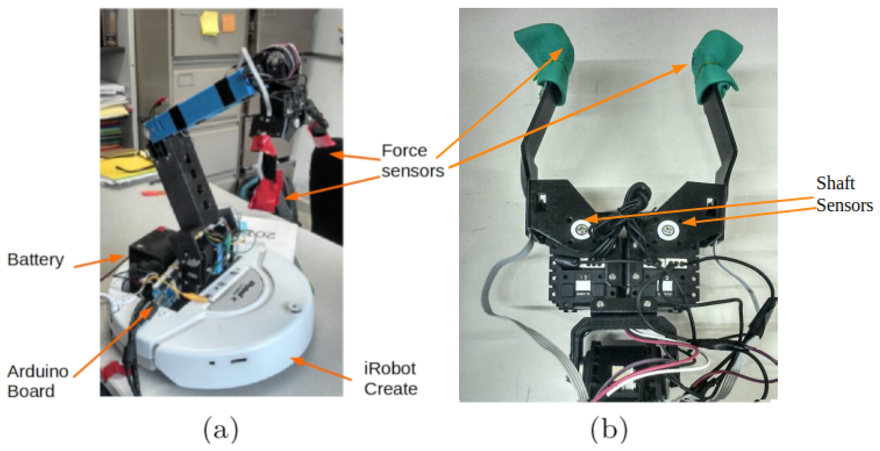
  • A two-independent-finger gripper. The gripper is composed of two Dynamixel AX-12 servo motors manufactured by CrustCrawler Robotics. Regarding the fingers, each finger is 10.16 cm long and is made of aluminum. Furthermore, they can be open up to 22.86 cm. An FFS-MT piezoelectric force sensor was placed at each fingertip (Figure 2b) The sensing force range for this sensor goes from 0 to 10 N, with an output resolution of 0.1 mV, providing a stable output over the range of force exerted. In addition, the output of this sensor exhibits linear behavior, as described in [36].
  • A three-degrees-of-freedom arm. The arm is operated through Dynamixel servo motors. These servo motors each include a micro-controller, which obtains the different states of the servo motor (e.g., speed, position, temperature, and voltage). The maximum lifting capability is 900 g. A data acquisition board (Arduino) and a 12 V battery were placed on the back of the robotic arm (Figure 2a). The data acquisition board processes the signals from each force sensor and sends them to the computer.
  • An iRobot Create. The robotic arm and gripper are mounted on an iRobot Create (mobile base). The iRobot allows moving the robotic arm from one place to another; therefore, objects may be repositioned.

4. Communication with an ROS

In this work, an ROS was used to communicate with all different systems of the robot. Software packages called nodes run independently from each other. In order to exchange information, the nodes send messages, enclosed in the form of topics. Messages are received from publishers and sent to subscribers directly from the master server of the ROS. Therefore, nodes do not directly communicate with each other.
Figure 3 shows a reduced scheme of the nodes and their communication messages on the robotic platform. Two nodes are used to communicate with the hardware: (a) the serial_node receives signals from piezoelectric-force sensors on each finger and encapsulates the signal in a message, which is sent to the ROS; and (b) the dynamixel_manager reads from the ROS the commands for each motor and returns messages about the state of these. A node called Force_Position_controller is in charge of reading “sensor signals” topics and writing commands to “motor-speed” topics. It is at this node where all control computation is performed.

5. Grasping Stage

As has been stated in Section 1, the grasping stage refers to the action of closing the gripper to take and manipulate the object properly. In order to arrive at this stage, some considerations have to be taken into account.
Generally, mobile robotic manipulators dispose of a perception system that provides the object’s information (position, shape, color, etc.) to the arm control system. The perception system can be composed of cameras, laser range finders, depth cameras, or a combination of these sensors. Once the perception system recognizes an object, it sends its information to the position and arm controllers to do the pre-grasping stage. In this work, those stages were realized. In other words, an object’s size and position were calculated and the arm was driven to reach the object. However, due to uncertainty in: (a) the relative position of the mobile base, (b) associated with onboard sensors, and (c) due to the control and motion of the arm’s joints, the position of end-effector can be slightly different than planned. Therefore, the object’s position relative to the gripper can be one of those shown in Figure 4. Namely, the object could be placed in the center, shifted to the right, or shifted to the left between the two fingers. To avoid perception obstruction, as commonly happens with mobile robots, it was decided to not use visual surveying, and instead we used gripper sensor grasping control. The robotic arm used in this work has two-independent fingers with angular motion. Each finger was provided with a piezoelectric force sensor, imposing then, the use of one controller for each finger.

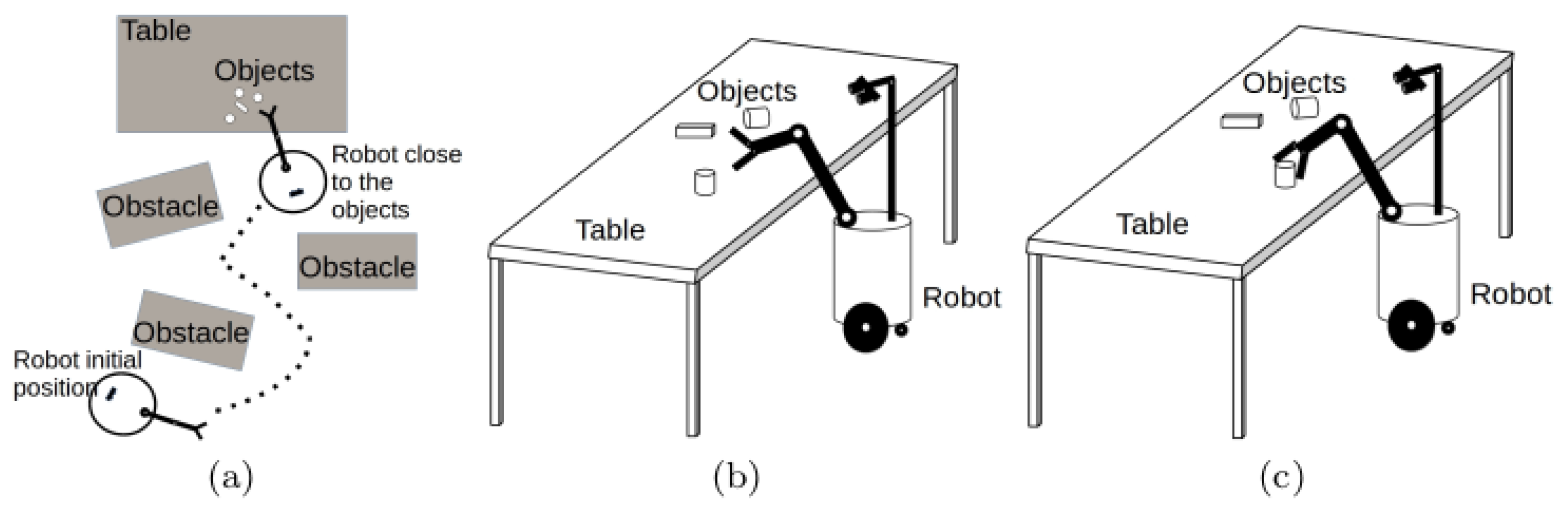
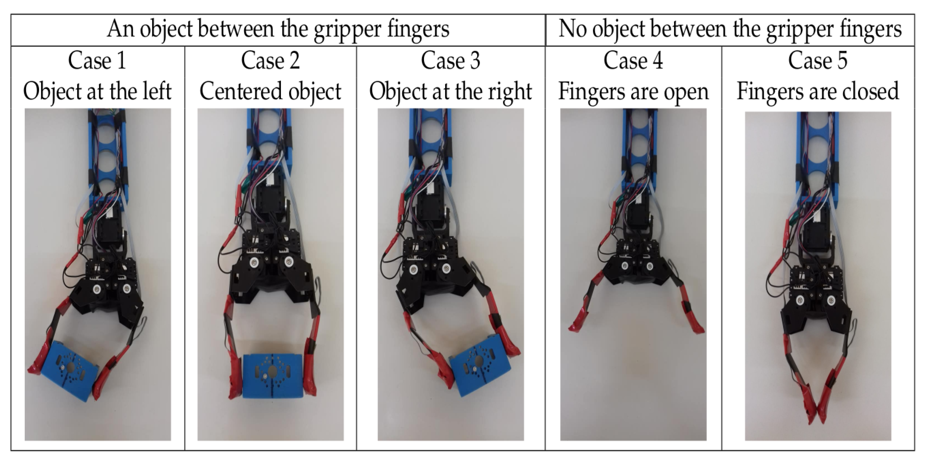
5.1. Problem Statement

Since the initial position of the object is practically known, the first thing that the gripper must do is to find and center the object. Three cases could be present: (i) the initial position of the object is in the center between the fingers; the (ii) the initial position of the object is near to the left finger; (iii) the initial position of the object is near to the right finger (Figure 4).
Then, before the gripper fingers can apply force to the object, it must be centered. If not, the differences in torques while exerting force with unbalanced fingers position can: damage the object or the motors, or make the object slide. Since, at the beginning, none of the force sensors are in contact, it was decided to divide the control system into two different objectives. The former, solving angular positions of the fingers about the object (angular position), and the latter, taking into account the force sensors when they are active. To deal with these two objectives, it was decided to design a PID position controller and a PID force controller, commuting between them the issues regarding position errors. Once we designed and applied those controllers, and considering the global task of firm and safely handling, the performances of these controllers were not very satisfying. Thus, to compare results, but above all, to increase performance, it was decided to design two fuzzy controllers (one Mamdani type and another type-II). Their advantage over PID controllers is that it is possible to have a different output for each fuzzy-controller, and to avoid sensors’ noise, which affects system performance.
Control objectives. Considering that the robotic arm has its gripper near to the object’s position, and taking into account the structure of the gripper, the objective of the gripper control system is to achieve firm and delicate object manipulation with the measurement of the angular position and force exerted by each finger. Then, (see Figure 4), it was necessary to design two-feedback laws, position control and force control, such that:
lim t e p ( t ) h = lim t ( R e f p o s P o s ω ( t ) ) h , h = ± 2 R e f p o s
lim t e f ( t ) = 0 = lim t ( R e f f o r c e F ( t ) ) = 0

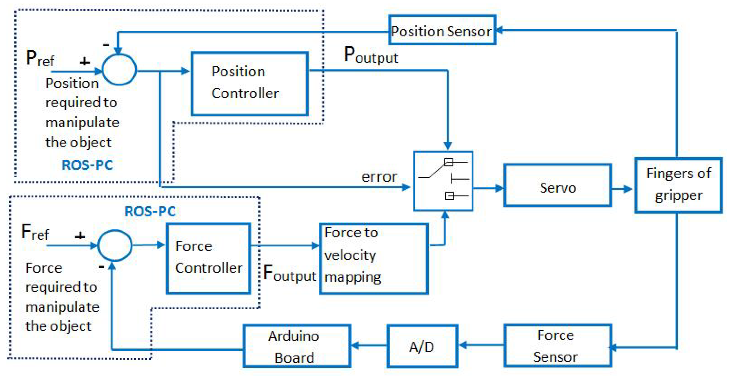
5.2. Design and Implementation of the Controllers

To manipulate an object, the forces applied by the fingers generally are sufficient to counteract gravitational and inertial components of the load force acting on the fingertips [37]. Due to the architecture of the two-independent-finger gripper used on the robotic manipulator, the controllers should perform two main tasks: (i) to place and keep the object at the desired position (i.e., position control), and (ii) to regulate the force applied to the object (i.e., a force control). To accomplish these tasks, three controllers are proposed: a hybrid PID controller (position–force), a type-I fuzzy controller (Mamdani), and a type-II fuzzy controller.
These controllers might use the following inputs provided by the robotic manipulator: two readings from angular positions (right P o s R ω ( t ) and left P o s L ω ( t ) ) and two readings, one each from the force sensor of each finger (right F R ( t ) and left F L ( t ) ).
On the other hand, the controllers produce a speed command as an output, i.e., two speeds, M R ( t ) and M L ( t ) , which will be applied to the right and left servo motors, respectively.

5.3. Position–Force Hybrid PID Controller

As mentioned previously, PID controllers are widely used in the industry for implementing control systems. Due to its operational ease and low cost, the first implemented controller is based on a hybrid PID scheme; i.e., it consists of two PID controllers: a position PID and a force PID operating in a switching mode as shown in Figure 5. It is important to remark that either of the gripper fingers uses this control scheme.
The first controller is responsible for placing and keeping the object at desired position. This controller works as follows: it switches on when the object is not centered, and it switches off when the object is centered. On the other hand, the force controller ensures that the fingers will apply enough force to manipulate an object firmly. This controller works when the position controller is switched off; i.e., the position error is zero.

5.3.1. Position Control

A discrete PID algorithm is used to implement the position PID in the ROS. This algorithm replaces the derivative term using a backward difference method and the integral term using a rectangular integration method. The discrete form of position algorithm for PID is given as:
u p ( t ) = u p ( t 1 ) + [ K p p + K p p T s p T i p + K p p T d p T s p ] e p ( t ) + [ K p p + K p p T s p T i p + 2 K p p T d p T s p ] e p ( t 1 ) + K p p T d p T s p e p ( t 2 )
where u p ( t ) is the control input, K p p is the proportional gain, T i p is integral time, T d p is derivative time or rate time, and e ( t ) stands for the error between the reference and process output. The values of K p p = 0.000001 , K i p = K p p T s p T i p = 0.0001 , and K d p = K p p T d p T s p = 0.001 were chosen using the Ziegler-Nichol tuning rule. T s p is the sampling period and e p ( t ) = R e f p o s P o s ω ( t ) is the position error.
In this case, the position reference is the center of the gripper. When the position error is sufficiently small e p ( t ) h with h = ± 2 % R e f p o s , a change is sent to the force PID controller.

5.3.2. Force Control

The force PID controller has a similar structure to the position PID controller.
u f ( t ) = u f ( t 1 ) + [ K p f + K i f + K d f ] e f ( t ) + [ K p f + K i f 2 K d f ] e f ( t 1 ) + K d f e f ( t 2 )
where K p f = 0.5 , K i f = K p f T s f T i f = 0.005 , and K d f = K p f T d f T s f = 0.001 are the proportional, integral, and derivative gains, respectively. u f ( t ) is the control input, T i f is integral time, T d f is derivative time or rate time, and T s f is the sampling period. e f ( t ) = R e f f o r c e F ( t ) is the force error. The R e f f o r c e is computed according to the object’s weight and material; thus, damage on the object might be reduced.

5.4. Type-I and Type-II Fuzzy Controllers

Fuzzy control provides a formal methodology for representing, manipulating, and implementing human heuristic knowledge about how to control a system. There are type-I fuzzy systems and type-II fuzzy systems.
Generally, in a type-I fuzzy controller, crisp input values are translated to fuzzy input values (fuzzification). These fuzzy input values are computed using rules to produce fuzzy output values (inference process). Finally, these fuzzy output values are mapped to crisp output values (defuzzification). It can be noticed that there are two conversions from crisp values to fuzzy values in a fuzzy controller. To achieve these conversions, it is necessary to define fuzzy sets. A type-I fuzzy set is an extension of a classical set (see Figure 6a). In a classical set, an element can (membership value = 1) or cannot (membership value = 0) be a member of a set (see blue lines in Figure 6a). Conversely, an element can be a member of a type-I fuzzy set at different membership values; i.e., the membership value can range from 0 to 1 (see red lines in Figure 6a). There are four basic membership functions: singleton, triangular, trapezoidal, and Gaussian distribution curve.
Frequently, these membership functions can be designed using knowledge from experts; nevertheless, other studies have used genetic algorithms [38,39] when the defining parameters is challenging. Consequently, type-I fuzzy sets might deal with more uncertainties than classical sets due to the definitions of membership functions.
Regarding the inference process, rules are implemented in order to map the fuzzy inputs to fuzzy outputs. These rules are expressed as IF–THEN statements. The “IF” part is composed of antecedents, which connect the fuzzy inputs, whereas the “THEN” part is composed of consequents, which connect the fuzzy outputs. Generally, the antecedents are defined using two basic operators: and; or. During the inference process, it is frequently the case that more than two rules are fired according to their strengths; therefore, an aggregation operation is performed to join the rules that were fired. These fired rules will define the fuzzy outputs. Finally, the fuzzy outputs are translated to crisp output values using a defuzzification method.
According to [40], type-I fuzzy controllers might face uncertainties in: (i) their control inputs due to noise affecting the sensors; (ii) their control outputs because of a change in the characteristics of the actuators; (iii) linguistic uncertainties because experts might have different meanings for the linguistic labels. Therefore, they implemented rules using the same antecedents and by changing the consequents. Interval type-II fuzzy controllers might cope with these uncertainties. Fuzzy inputs and fuzzy outputs of an interval type-II fuzzy controller are implemented using interval type-II fuzzy sets. These sets add a second level of membership functions; therefore, these interval type-II fuzzy sets have upper and lower membership functions (see Figure 6b). Additionally, a footprint of uncertainty can be seen in these sets, which is the area between the upper and lower membership functions.
Interval type-II fuzzy controllers perform fuzzification, inference, and defuzzification processes. Furthermore, the interval type-II fuzzy controllers execute the fuzzification and evaluation of rules, as the type-I fuzzy controllers do. The key differences between interval type-II and type-I fuzzy controllers are: (i) interval type-II fuzzy controllers use interval type-II fuzzy sets in the antecedents and consequents of the rules; and (ii) after evaluating the rules, interval type-II fuzzy controllers perform a reduction from type-II fuzzy sets to type-I fuzzy sets using a type-reducer. Once this reduction is carried out, a defuzzifier is applied to obtain the crisp output.

5.4.1. Type-I Fuzzy Controller for Position and Force Control

Figure 7 presents the design of the type-I fuzzy controller. As can be seen, the controller works as follows:
1.
Firstly, crisp values are obtained from each finger of the gripper. Specifically, angular positions ( P o s R ω ( t ) , P o s L ω ( t ) ) and the two readings of force sensors ( F R ( t ) F L ( t ) ) of each finger are inputs to the fuzzy controller.
2.
Secondly, these crisp values are translated into input-linguistic values using trapezoidal membership functions. This stage is called fuzzification.
3.
Thirdly, rules are evaluated to compute the output-linguistic values. This process is called fuzzy inference.
4.
Finally, the output-linguistic values are translated into two crisp values— M R ( t ) and M L ( t ) , which are the speed values for the right and left servo motors using a defuzzification method.
Eight fuzzy input sets were designed and implemented using trapezoidal membership functions for transforming the angular positions and force readings into linguistic values. Focusing on force readings, four trapezoidal membership functions were implemented to transform F R ( t ) and F L ( t ) into the following four possible linguistic values: S e n s o r X O f f ( S X O ), S e n s o r X S o f t T o u c h ( S X T S ), S e n s o r X T o u c h H a r d ( S X T H ), and S e n s o r X S q u e e z e ( S X S Q ), where X is R for the right sensor and L for the left sensor.
Regarding the angular positions of the motor, four trapezoidal membership functions were implemented in order to transform P o s R ω ( t ) , P o s L ω ( t ) into the following linguistic values: V e r y O p e n X M o t o r ( V O X M ), O p e n X M o t o r ( O X M ), C e n t e r X M o t o r ( C X M ), and C l o s e d X M o t o r ( C L X M ), where X is R for the right motor and L for the left motor.
On the other hand, in terms of fuzzy output sets, sixteen singleton membership functions were used for the two outputs of the fuzzy inference, eight for each finger. Moreover, it can be seen from Figure 8 that the linguistic labels are named R 1 , R 2 , R 3 , R 4 , R 5 , R 6 , R 7 , and R 8 for the right finger and L 1 , L 2 , L 3 , L 4 , L 5 , L 6 , L 7 , and L 8 for the left finger. These linguistic values are ordered from the lowest speed value to the highest possible speed value of the command motor.
Table 1 presents the fifty fuzzy rules that were created using th fuzzy sets. The rules have the following structure: IF F L AND F R AND P o s L ω ( t ) AND P o s R ω ( t ) , THEN M L ( t ) , M R ( t ) . As can be seen, these rules correspond to the type of Mamdani fuzzifier using minimum implication, i.e., the “AND” operator for connecting the antecedents.
In order to design the set of fuzzy rules, two basic scenarios were considered: the gripper has an object between its fingers, and there is no object between the gripper fingers (see Figure 9). In the first scenario, the gripper might be located at different positions with respect to the center of the object to be grasped. Specifically, there are three basic cases that the gripper might face in terms of the position of the object to be grasped:
  • Case 1. The object is located on the left side concerning the center of the gripper (Table 1: rules 1–3).
  • Case 2. The object is at the center of the gripper (Table 1: rules 4–9).
  • Case 3. The object is located on the right side with respect to the center of the gripper (Table 1: rules 6, 10–11).
On the other hand, in the second scenario, there are two cases:
  • Case 4. The gripper fingers are open (Table 1: rule 12).
  • Case 5. The gripper fingers are closed (Table 1: rule 13).
Additionally, there are other cases in which the object might be located at a position which is between two cases (Table 1: rules 14–50); i.e., the object might be located at a position between the left region (case 1) and the center point (case 2).
It is important to note that during the evaluation of rules, several rules might be fired; therefore, “maximum aggregation” is applied in this case. Finally, to obtain the two speed values, M R ( t ) , M L ( t ) , “center of gravity” was used as the defuzzifaction technique.

5.4.2. Type-II Fuzzy Controller for Position and Force Control

Figure 10 shows the interval type-II fuzzy input sets for the four inputs < F R ( t ) , F L ( t ) , P o s R ω ( t ) , and P o s L ω ( t ) > ; and interval type-II fuzzy output sets for the two outputs < M R ( t ) and M L ( t ) > . Both types of fuzzy sets are for the right finger. It can be seen that upper membership functions were added to both types of fuzzy sets (fuzzy input sets and fuzzy output sets) defined in the type-I fuzzy controller.
The fuzzy rules for the type-II fuzzy controller are the same as those implemented for the type-I controller. These rules correspond to the Mamdani fuzzifier and employ minimum implications. However, the type-II fuzzy controller uses 50 fuzzy rules for the upper membership functions and 50 rules for the lower membership functions. Table 2 shows a summary of these rules. As mentioned earlier, a key difference between type-I and type-II controllers is that type-II uses a type-reducer to transform type-II fuzzy sets to type-I fuzzy sets.
The type-II fuzzy controller employs the Karnik–Mendel (KM) algorithm as the type-reducer. The KM algorithm [41,42] computes the lower and upper intervals of the type-II fuzzy outputs for the left and right motors. For instance, the command for the left motor Y i (output) is composed of two intervals [ y ̲ i , y ¯ i ] , where y ̲ i is the lower left command motor, and y ¯ i is the upper left command motor. Therefore, the KM algorithm corresponding to the left motor works as follows:
1.
Firstly, the lower left motor ( y l ) is computed in the following manner:
(a)
y l i is sorted in ascending order, where y l i is the lower left motor.
(b)
y l is computed as
y l = i = 1 M f l i y l i i = 1 M f l i
where f l i = f ¯ i + f ̲ i 2 and f ¯ i , f ̲ i are the firing intervals. Let y l = y l .
(c)
Find S, such that y l S y l y l S + 1 .
(d)
Find y l = i = 1 M f l i y l i i = 1 M f l i with f l i = f ̲ i for i S and f l i = f ¯ i for i > S . Let y l = y l .
(e)
If y l y l , go to step 6. If y l = y l , set y l = y l , and stop.
(f)
Let y l = y l , and go to step 3.
2.
Secondly, the upper left motor ( y u ) is calculated using the previous steps; but y u , y u , y u , y u i , y u U , y u U + 1 , f u i and U instances are used instead of y l , y l , y l , y l i , y l L , y l L + 1 , f l i and L instances.
3.
Finally, the defuzzification process is performed; i.e., the average of y l and y u is computed to be used as the crisp value for the left motor ( Y f i n a l ):
Y f i n a l = ( y u + y l 2 ) .
These steps are repeated using the lower and upper intervals for the right motor to compute the crisp value for the right motor.

6. Results and Discussion

The robotic manipulator performs a set of actions in order to grasp an object firmly. The configuration of sensors placed at the fingertips, i.e., a sensor surrounded by a foamy surface, permits the grasping of different objects with diverse shapes. For instance, Figure 11 shows the process of grasping a solid plastic box. The set of actions can be divided into three stages:
  • Stage 1. The main goal of this stage is to center the object with respect to the center of the gripper. Assuming that the position of the object is known, the gripper starts approaching the object. Once the gripper has touched the object, it proceeds to position the object according to its center (the center of the gripper). This stage is known as “positioning” (Figure 11a–e).
  • Stage 2. Once the object has been centered according to the gripper, the fingers apply specific forces grasp firmly the object; consequently, the object is less vulnerable to falling. As soon as the object has been grabbed, the base of the robot begins rotating for 4.6 s, which is sufficient time for the base to rotate approximately 180 degrees. At this stage, the force PID, type-I, and type-II have to regulate the force to be applied. This stage is known as “force” (Figure 11f–j).
  • Stage 3. Finally, once the base of the robot has stopped, the arm moves down so that the gripper can release and position the object on the table (Figure 11k,l).
Figure 12 presents the results from grasping a solid plastic box with a width of 6 cm. This action involved the three stages explained earlier. It is important to recall that the hybrid PID is composed of a position PID and a force PID; consequently, these two PIDs were switched on and off according to the action being performed. These changes are indicated at the bottom of Figure 12. Data were continuously collected for 18 s at a sampling rate of 100 Hz.
It can be seen that the controllers coped with two key control tasks to grasp an object firmly: positioning and force. Regarding the positioning, the three controllers computed position references for each finger of the gripper at stage 1. It can be noticed from Figure 12 that to locate the object at the middle of the gripper, type-I and type-II fuzzy controllers decreased their initial position reference values for the left finger and increased their initial position reference values for the right finger. The three controllers obtained 1.8 rads as the reference position for the left finger, whereas the three controllers obtained a position reference of 3.4 rads for the right finger. In terms of force, the force regulation reference was 60 mV for both fingers. This reference value avoided damage to the object and excessive forces being exerted by the gripper motors. It can be seen that the type-I controller achieved the reference value for the left finger faster than type-II and PID controllers. Moreover, type-II and PID controllers did not achieve the force reference for the right finger. It is important to remark that from 3.62 s to 6.073 s, the hybrid PID switched from a positioning control task to a force control task, whereas the fuzzy controllers performed both control tasks (positioning and force regulation) simultaneously.
Focusing on stage 2, it can be seen that the three controllers achieved the reference values in terms of position for both fingers. However, regarding force, the three controllers achieved values for the left finger close to the reference, but only the type-I fuzzy controller obtained values for the right finger close to the reference. Additionally, the hybrid PID controller generated various oscillations during this stage. This fact might be related to the switching between the PIDs.
Particularly, as is shown in Figure 12, there are some spikes in the PID controller’s force graph. These spikes correspond to a commutation between PID controllers from force to position. In other words, while the force controller was handling the object, it moved out of the centered position, making commutation necessary to center the object again. Therefore, force sensors measure the inverse force response in relation to the finger motion; i.e., when a spike in force is downward for the right finger, this spike is upward for the left finger, corresponding to an action to center the object.
Finally, the fuzzy controller achieved the reference values in terms of position for both fingers. Regarding the force, the fuzzy controllers obtained values for the left finger close to the reference. It is important to note that the hybrid PID controller generated oscillations at this stage.
For comparison purposes between the PID, fuzzy type-I and fuzzy type-II controllers, 20 experiments were carried out, obtaining the average values of: rise time t r and settling time t s . Table 3 shows the values of the rise time, the settling time, the setpoint, and the type of response. In the same table, it can be observed that all responses were overdamping and the PID had the higher values of t r and t s , indicating poor performance.
In order to perform a preliminary comparison of these controllers, the integral absolute error (IAE) and integral time of absolute error (ITAE) were computed. It can be seen from Table 4 that the type-I fuzzy controller obtained the lowest IAE and ITAE values, whereas the hybrid PID controller resulted in the highest IAE and ITAE values.

7. Conclusions

In this paper, a hybrid position-force PID controller, a type-I fuzzy controller, and a type-II fuzzy controller were designed and implemented to grasp an object through a three-fold arm with an independent two-finger gripper. From the results, it can be concluded that the hybrid PID controller generated oscillations in stages 2 and 3 of manipulating the object due to switching between the position PID and the force PID. On the other hand, few oscillations were generated over the three stages of object manipulation with the type-II fuzzy controller. Moreover, it was able to calculate values close to the references in terms of position for both fingers; but in terms of force, it was able to calculate the appropriate value only for the left finger. As for the type-I fuzzy controller, it obtained the best performance, because few oscillations were generated in the three stages of object manipulation, and its t r and t s values are practically the same. Despite the type-II fuzzy controller having a lower t r in the position controller, it had a higher t s in the force controller and it had more oscillations. The type-I fuzzy controller was able to calculate values close to the reference values in terms of position and force for both fingers.

Author Contributions

Conceptualization, S.H.-M., A.M.-H. and E.R.P.-H. Formal analysis, E.R.P.-H., E.J.R.-R. and H.V.-L. Investigation, S.H.-M. Supervision, A.M.-H. and E.R.P.-H. All authors have read and agreed to the published version of the manuscript.

Funding

This research received no external funding.

Conflicts of Interest

The authors declare that they have no conflict of interest.

References

  1. Miller, A.T.; Knoop, S.; Christensen, H.I.; Allen, P.K. Automatic grasp planning using shape primitives. In Proceedings of the IEEE International Conference on Robotics and Automation—ICRA’03, Taipei, Taiwan, 14–19 September 2003; Volume 2, pp. 1824–1829. [Google Scholar]
  2. Berenson, D.; Diankov, R.; Nishiwaki, K.; Kagami, S.; Kuffner, J. Grasp planning in complex scenes. In Proceedings of the 2007 7th IEEE-RAS International Conference on Humanoid Robots, Pittsburgh, PA, USA, 29 November–1 December 2007; pp. 42–48. [Google Scholar]
  3. Hasegawa, T.; Murakami, K.; Matsuoka, T. Grasp planning for precision manipulation by multifingered robotic hand. In Proceedings of the 1999 IEEE International Conference on Systems, Man, and Cybernetics—SMC’99, Tokyo, Japan, 12–15 October 1999; Volume 6, pp. 762–767. [Google Scholar]
  4. Bley, F.; Schmirgel, V.; Kraiss, K.F. Mobile manipulation based on generic object knowledge. In Proceedings of the 15th IEEE International Symposium on Robot and Human Interactive Communication—ROMAN 2006, Hatfield, UK, 6–8 September 2006; pp. 411–416. [Google Scholar]
  5. Kappler, D.; Chang, L.; Przybylski, M.; Pollard, N.; Asfour, T.; Dillmann, R. Representation of pre-grasp strategies for object manipulation. In Proceedings of the 2010 10th IEEE-RAS International Conference on Humanoid Robots (Humanoids), Nashville, TN, USA, 6–8 December 2010; pp. 617–624. [Google Scholar]
  6. Sanchez-Lopez, J.R.; Marin-Hernandez, A.; Palacios-Hernandez, E.R.; Rios-Figueroa, H.V.; Marin-Urias, L.F. A Real-time 3D Pose Based Visual Servoing Implementation for an Autonomous Mobile Robot Manipulator. Procedia Technol. 2013, 7, 416–423. [Google Scholar] [CrossRef] [Green Version]
  7. Tai, K.; El-Sayed, A.R.; Shahriari, M.; Biglarbegian, M.; Mahmud, S. State of the Art Robotic Grippers and Applications. Robotics 2016, 5, 11. [Google Scholar] [CrossRef] [Green Version]
  8. Khurshid, A.; Ghafoor, A.; Malik, M.A. Robotic Grasping and Fine Manipulation Using Soft Fingertip; IntechOpen: London, UK, 2011. [Google Scholar]
  9. Nee, A.Y. Handbook of Manufacturing Engineering and Technology; Springer: London, UK, 2015. [Google Scholar]
  10. Ang, K.H.; Chong, G.; Li, Y. PID control system analysis, design, and technology. IEEE Trans. Control Syst. Technol. 2005, 13, 559–576. [Google Scholar]
  11. Ang, K.H.; Li, Y. Survey on PID Control System Design and Tuning Software Tools. In Proceedings of the 5th Asia-Pacific Conference On Control and Measurement, Dali, China, 8–12 July 2002; pp. 12–17. [Google Scholar]
  12. Bhagwan, S.; Anil Kumar, J.S.S. A Review on: PID Controlle. Int. J. Recent Technol. Mech. Electr. Eng. (IJRMEE) 2016, 3, 17–22. [Google Scholar]
  13. O’Dwyer, A. Handbook of PI and PID Controller Tuning Rules; World Scientific: Singapore, 2009. [Google Scholar]
  14. Das, S.; Guha, D.; Dutta, B. Medical diagnosis with the aid of using fuzzy logic and intuitionistic fuzzy logic. Appl. Intell. 2016, 45, 850–867. [Google Scholar] [CrossRef]
  15. Lee, Z.J. A robust learning algorithm based on support vector regression and robust fuzzy cerebellar model articulation controller. Appl. Intell. 2008, 29, 47–55. [Google Scholar] [CrossRef]
  16. Zadeh, L.A. Fuzzy sets. Inf. Control 1965, 8, 338–353. [Google Scholar] [CrossRef] [Green Version]
  17. Hayward, G.; Davidson, V. Fuzzy logic applications. Analyst 2003, 128, 1304–1306. [Google Scholar] [CrossRef]
  18. Yager, R.R.; Zadeh, L.A. An Introduction to Fuzzy Logic Applications in Intelligent Systems; Springer Science & Business Media: New York, NY, USA, 2012; Volume 165. [Google Scholar]
  19. Lee, C.S.; Wang, M.H.; Hsu, C.Y.; Chen, Z.W. Type-2 fuzzy set and fuzzy ontology for diet application. In Advances in Type-2 Fuzzy Sets and Systems; Springer: New York, NY, USA, 2013; pp. 237–256. [Google Scholar]
  20. Son, C. Similarity measuring strategy of image patterns based on fuzzy entropy and energy variations in intelligent robot’s manipulative task. Appl. Intell. 2013, 38, 131–145. [Google Scholar] [CrossRef]
  21. Singh, S.; Garg, H. Distance measures between type-2 intuitionistic fuzzy sets and their application to multicriteria decision-making process. Appl. Intell. 2017, 46, 788–799. [Google Scholar] [CrossRef]
  22. Wang, L.; Liu, Z.; Chen, C.P.; Zhang, Y. Interval type-2 fuzzy weighted support vector machine learning for energy efficient biped walking. Appl. Intell. 2014, 40, 453–463. [Google Scholar] [CrossRef]
  23. Ali, F.; Kim, E.K.; Kim, Y.G. Type-2 fuzzy ontology-based opinion mining and information extraction: A proposal to automate the hotel reservation system. Appl. Intell. 2015, 42, 481–500. [Google Scholar] [CrossRef]
  24. Wang, X.; Fan, X.; Zhao, Y.; Ma, S. Parallel force control for a robot gripper based on grey prediction models. In Proceedings of the 2012 Power Engineering and Automation Conference, Wuhan, China, 18–20 September 2012; pp. 1–5. [Google Scholar] [CrossRef]
  25. Xie, Y.; Zhang, B.; Zhou, J.; Bai, Y.; Zhang, M. An Integrated Multi-Sensor Network for Adaptive Grasping of Fragile Fruits: Design and Feasibility Tests. Sensors 2020, 20, 4973. [Google Scholar] [CrossRef] [PubMed]
  26. Pastor, F.; Gandarias, J.M.; García-Cerezo, A.J.; Gómez-de Gabriel, J.M. Using 3D Convolutional Neural Networks for Tactile Object Recognition with Robotic Palpation. Sensors 2019, 19, 5356. [Google Scholar] [CrossRef] [PubMed] [Green Version]
  27. Costanzo, M.; De Maria, G.; Natale, C.; Pirozzi, S. Design and Calibration of a Force/Tactile Sensor for Dexterous Manipulation. Sensors 2019, 19, 966. [Google Scholar] [CrossRef] [Green Version]
  28. Widhiada, W.; Nindhia, T.; Budiarsa, N. Robust Control for the Motion Five Fingered Robot Gripper. Int. J. Mech. Eng. Robot. Res. 2015, 4, 226. [Google Scholar] [CrossRef]
  29. Ha, X.V.; Ha, C.; Nguyen, D.K. A general contact force analysis of an under-actuated finger in robot hand grasping. Int. J. Adv. Robot. Syst. 2016, 13, 14. [Google Scholar] [CrossRef] [Green Version]
  30. Ahmad, H.; Razali, S.; Mohamed, M.R. Fuzzy Logic Controller Design for A Robot Grasping System with Different Membership Functions. IOP Conf. Ser. Mater. Sci. Eng. 2013, 53, 012051. [Google Scholar] [CrossRef] [Green Version]
  31. Boughdiri, R.; Bezine, H.; Alimi, A.M. Fuzzy logic control for grasping 3d objects with sliding contacts. In Proceedings of the International Conference on Control, Engineering and Information Technology, Sousse, Tunisia, 4–7 June 2013; Volume 2, pp. 116–119. [Google Scholar]
  32. Dimeas, F.; Sako, D.V.; Moulianitis, V.C.; Aspragathos, N.A. Design and fuzzy control of a robotic gripper for efficient strawberry harvesting. Robotica 2015, 33, 1085–1098. [Google Scholar] [CrossRef]
  33. Su, K.H.; Huang, S.J.; Yang, C.Y. Development of robotic grasping gripper based on smart fuzzy controller. Int. J. Fuzzy Syst. 2015, 17, 595–608. [Google Scholar] [CrossRef]
  34. Ciobanu, V.; Popescu, N. Tactile controller using fuzzy logic for robot inhand manipulation. In Proceedings of the 2015 19th International Conference on System Theory, Control and Computing (ICSTCC), Cheile Gradistei, Romania, 14–16 October 2015; pp. 435–440. [Google Scholar]
  35. Jamil, M.F.A.; Jalani, J.; Ahmad, A. A new approach of active compliance control via fuzzy logic control for multifingered robot hand. Proc. SPIE 2016, 10011, 1001111. [Google Scholar] [CrossRef]
  36. Hernandez-Mendez, S.; Marin-Hernandez, A.; Palacios-Hernandez, E.R.; Vazquez-Leal, H. Characterization of two force sensors to be used in a robotic hand. In Proceedings of the 2015 International Conference on Electronics, Communications and Computers (CONIELECOMP), Cholula, Mexico, 25–27 February 2015; pp. 155–160. [Google Scholar]
  37. Johansson, R.; Westling, G. Roles of glabrous skin receptors and sensorimotor memory in automatic control of precision grip when lifting rougher or more slippery objects. Exp. Brain Res. 1984, 56, 550–564. [Google Scholar] [CrossRef] [PubMed]
  38. Horikawa, S.I.; Furuhashi, T.; Uchikawa, Y. On fuzzy modeling using fuzzy neural networks with the back-propagation algorithm. IEEE Trans. Neural Netw. 1992, 3, 801–806. [Google Scholar] [CrossRef] [PubMed]
  39. Wang, L.X.; Mendel, J.M. Fuzzy basis functions, universal approximation, and orthogonal least-squares learning. IEEE Trans. Neural Netw. 1992, 3, 807–814. [Google Scholar] [CrossRef] [Green Version]
  40. Hagras, H. Type-2 FLCs: A new generation of fuzzy controllers. IEEE Comput. Intell. Mag. 2007, 2, 30–43. [Google Scholar] [CrossRef]
  41. Karnik, N.N.; Mendel, J.M. Centroid of a type-2 fuzzy set. Inf. Sci. 2001, 132, 195–220. [Google Scholar] [CrossRef]
  42. Mendel, J.M. Uncertain Rule-Based Fuzzy Logic Systems: Introduction and New Directions; Prentice Hall PTR: Upper Saddle River, NJ, USA, 2001. [Google Scholar]
Figure 1. Actions prior to the object’s manipulation: (a) moving the robot so the object’s position is within the arm’s configuration space, (b) object detection and position estimation, and (c) planning and execution of trajectories to drive the arm close to the object.
Applsci 11 09827 g001
Figure 2. (a) An arm with three degrees of freedom, placed on a mobile robot (iRobot Create). On the back of the robot is a data acquisition board, as well as a 12 V battery to power the system. (b) Force sensors placed on each fingertip of the gripper.
Applsci 11 09827 g002
Figure 3. Communication structure of the gripper in the ROS. Nodes at the left are connected directly to hardware, whereas the node in the right (the controller) only communicates with hardware through messages sent to the public memory of ROS (at the center of the figure).
Applsci 11 09827 g003
Figure 4. Initial conditions for the object’s position being: (a) at the center with respect the fingers, (b) near the left finger, and (c) near to the right finger.
Applsci 11 09827 g004
Figure 5. Control scheme of the hybrid PID controller.
Applsci 11 09827 g005
Figure 6. Membership functions of (a) type-I FLS and (b) interval type-II FLS.
Applsci 11 09827 g006
Figure 7. Block diagram of the type-I fuzzy controller with the gripper.
Applsci 11 09827 g007
Figure 8. Type I membership functions for the inputs F R ( t ) and P o s R ω ( t ) and for the output M R ( t ) .
Applsci 11 09827 g008
Figure 9. Cases for the design of the fuzzy rules.
Applsci 11 09827 g009
Figure 10. Type II (upper and lower) membership functions for the inputs F R ( t ) and P o s R ω ( t ) , and for the output M R ( t ) .
Applsci 11 09827 g010
Figure 11. Sequence of actions to grasp an object during the experiments: (ae) approaching and centering the object; (fj) grasping and moving the object; (k,l) object’s release.
Applsci 11 09827 g011
Figure 12. Performance of each controller at each stage. In the above chart are the responses in positioning of motor left and motor right, ML and MR, respectively. In the below chart are the responses of sensor left and sensor right, SL and SR, respectively.
Applsci 11 09827 g012
Table 1. Fuzzy rules for the type-I fuzzy controller.
IF F L Operator F R Operator Pos L ω ( t ) Operator Pos R ω ( t ) THEN M L ( t ) , M R ( t )
1 S L T S AND S R O AND O L M AND C R M THEN L 4 , R 2
2 S L T S AND S R T S AND O L M AND C R M THEN L 4 , R 3
3 S L T S AND S R T S AND O L M AND C L R M THEN L 2 , R 2
4 S L T S AND S R T S AND O L M AND O R M THEN L 4 , R 4
25 S L T S AND S R O AND O L M AND O R M THEN L 4 , R 2
26 S L T S AND S R O AND C L M AND C R M THEN L 3 , R 3
27 S L T S AND S R O AND C L L M AND C L R M THEN L 3 , R 2
28 S L T S AND S R O AND O L M AND C R M THEN L 4 , R 2
47 S L T H AND S R O AND C L L M AND C L R M THEN L 4 , R 4
48 S L O AND S R T H AND C L M AND C R M THEN L 4 , R 2
49 S L O AND S R T H AND C L L M AND C L R M THEN L 4 , R 2
50 S L O AND S R T H AND C L M AND C L R M THEN L 4 , R 2
Table 2. Fuzzy rules for interval type-II fuzzy controller. F ̲ i stands for lower membership, F ¯ i stands for upper membership, M L ( t ) is [ y ̲ L i , y ¯ L i ] , and M R ( t ) is [ y ̲ R i , y ¯ R i ] .
IF F L Operator F R Operator Pos L ω ( t ) Operator Pos R ω ( t ) THEN M L ( t ) , ( M R ( t ) )
[ F ̲ 1 , F ¯ 1 ] = S L O ̲ AND S R O ̲ AND V O L M ̲ AND V O R M ̲ THEN [ y ̲ L 1 , y ¯ L 1 ] = [ 0.4 , 0.8 ]
S L O ¯ AND S R O ¯ AND V O L M ¯ AND V O R M ¯ [ y ̲ R 1 , y ¯ R 1 ] = [ 0.5 , 0.9 ]
[ F ̲ 34 , F ¯ 34 ] = S L T H ̲ AND S R T H ̲ AND C L M ̲ AND C R M ̲ THEN [ y ̲ L 34 , y ¯ L 34 ] = [ 2.0 , 2.8 ]
S L T H ¯ AND S R T H ¯ AND C L M ¯ AND C R M ¯ [ y ̲ R 34 , y ¯ R 34 ] = [ 1.1 , 1.9 ]
[ F ̲ 50 , F ¯ 50 ] = S L O ̲ AND S R T H ̲ AND C L M ̲ AND C L R M ̲ THEN [ y ̲ L 50 , y ¯ L 50 ] = [ 2.0 , 2.8 ]
S L O ¯ AND S R T H ¯ AND C L M ¯ AND C L R M ¯ [ y ̲ R 50 , y ¯ R 50 ] = [ 0.5 , 0.9 ]
Table 3. Performances t s and t r in a hybrid PID controller, and in type-I and type-II fuzzy controllers.
ControllerPosition MRPosition MLForce SRForce SL
PID2.936.53113.31
t r Fuzzy I3.0093.0003.003.00
Fuzzy II2.7053.313.913.31
PID3.6710.767.54.5
t s Fuzzy I3.313.53.34.2
Fuzzy II3.613.964.5
Setpoint 3.4 rad1.8 rad60 mV60 mV
Response OverdampingOverdampingOverdampingOverdamping
Table 4. Comparison among the hybrid PID controller, and the type-I and type-II fuzzy controllers.
ControllerIAEITAE
Hybrid PID10,278.547,901.75
Type-1FLC6846366.08
Type-2FLC4864.2531,878.23
Publisher’s Note: MDPI stays neutral with regard to jurisdictional claims in published maps and institutional affiliations.

