
Structural Behavior of Composite Floor System Using Cold-Formed Thin-Walled C Steel Channel Embedded Foam Concrete


Abstract
:1. Introduction
2. Four-Point Bending Test
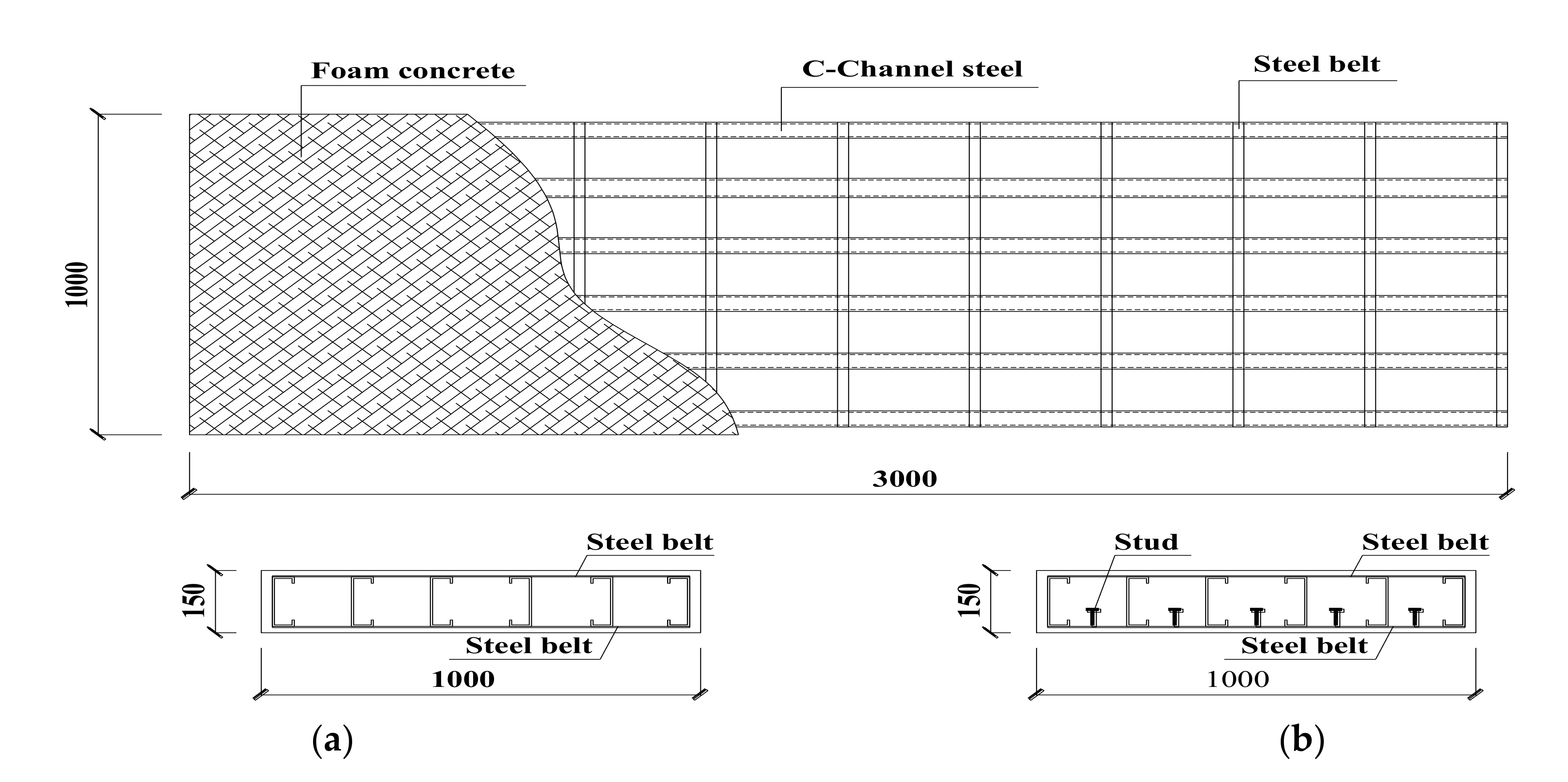
2.1. Test Specimens
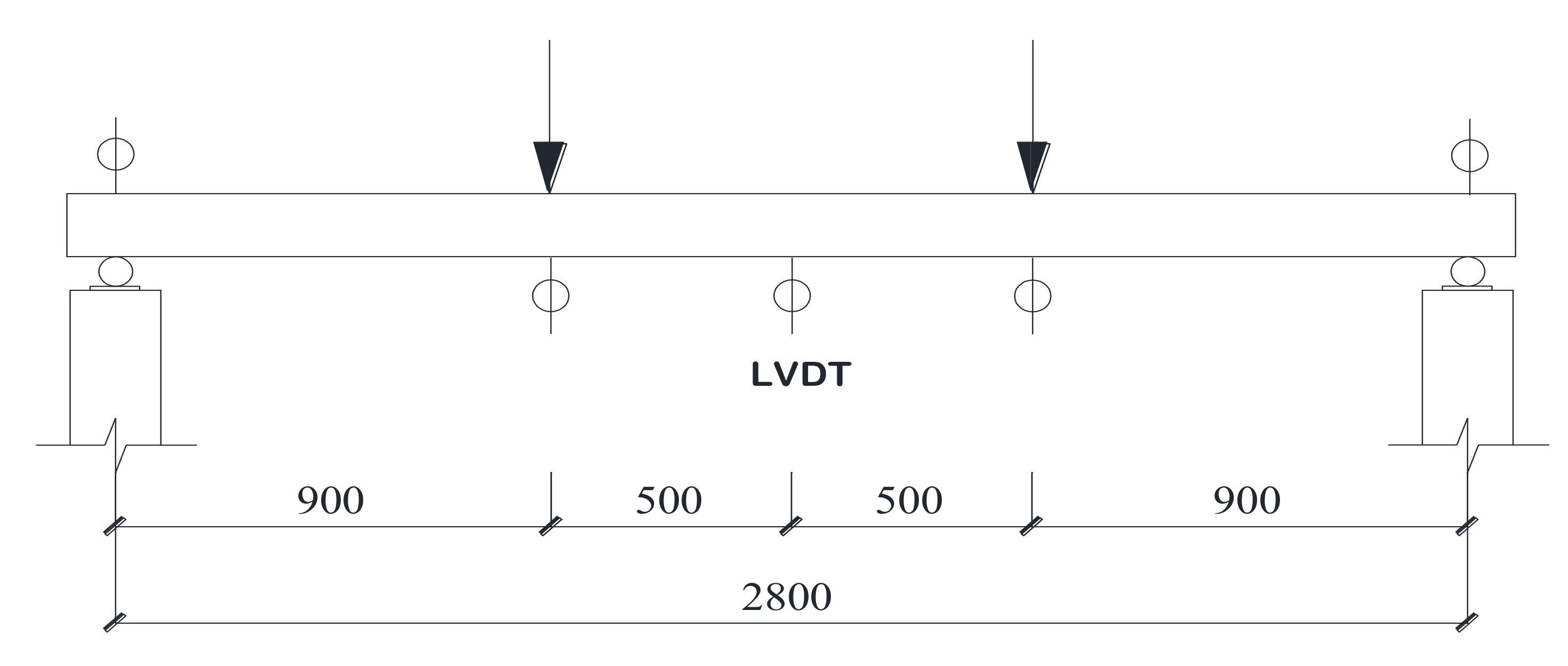
2.2. Test Set-Up
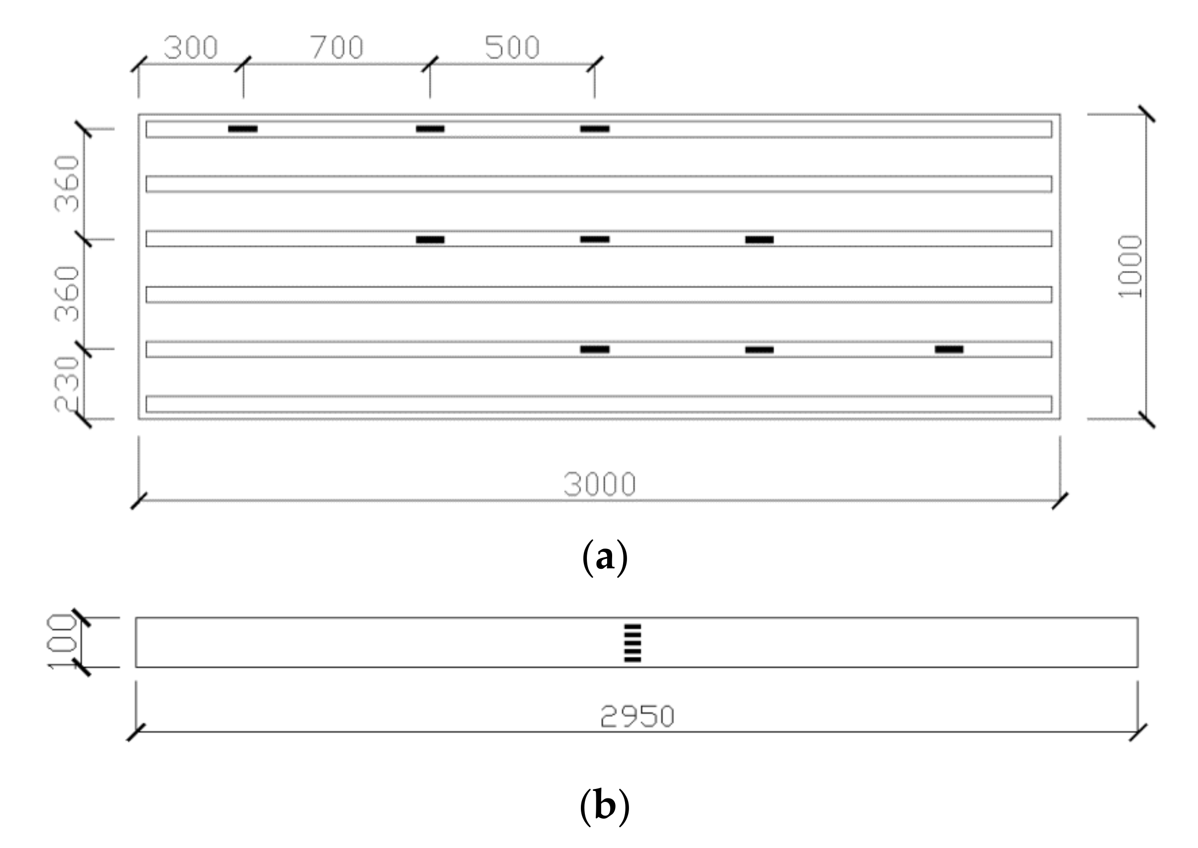
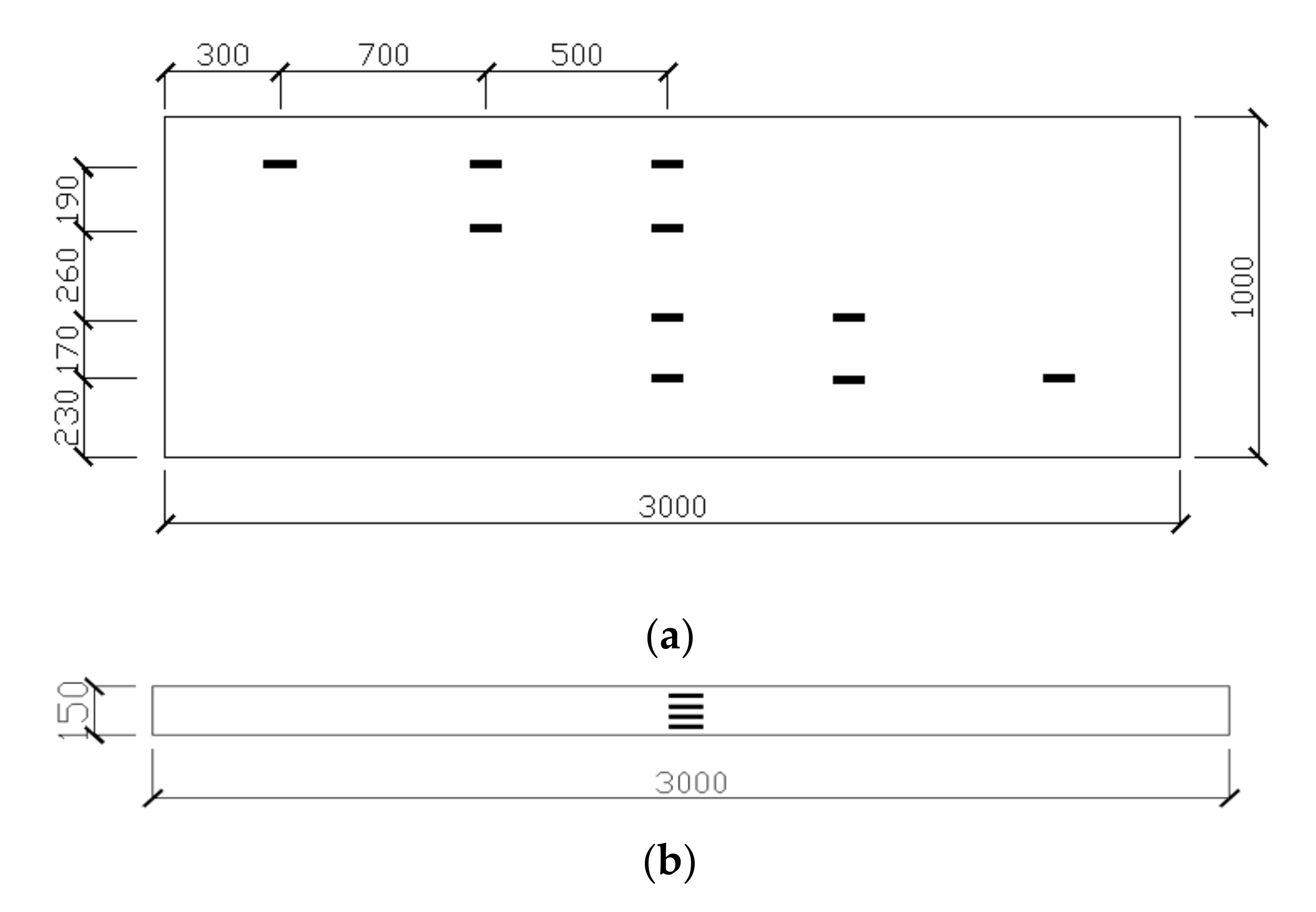
2.3. Instrumentation
2.4. Loading Procedure
2.5. Test Results and Discussion
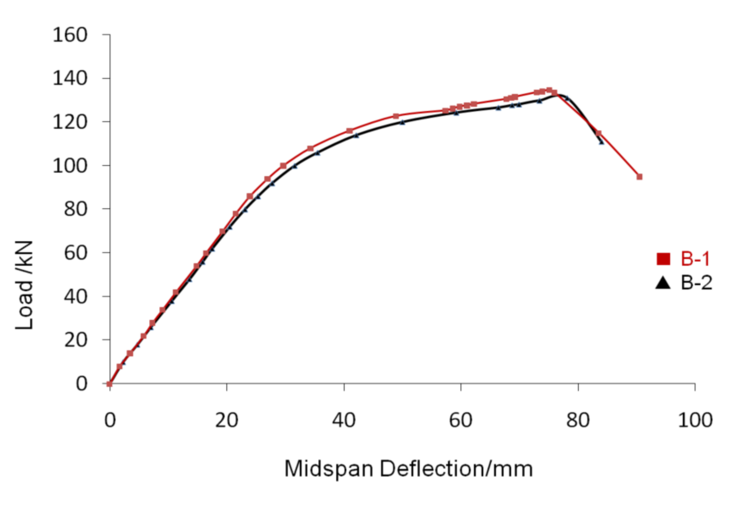
2.5.1. Load-Deflection Relationship
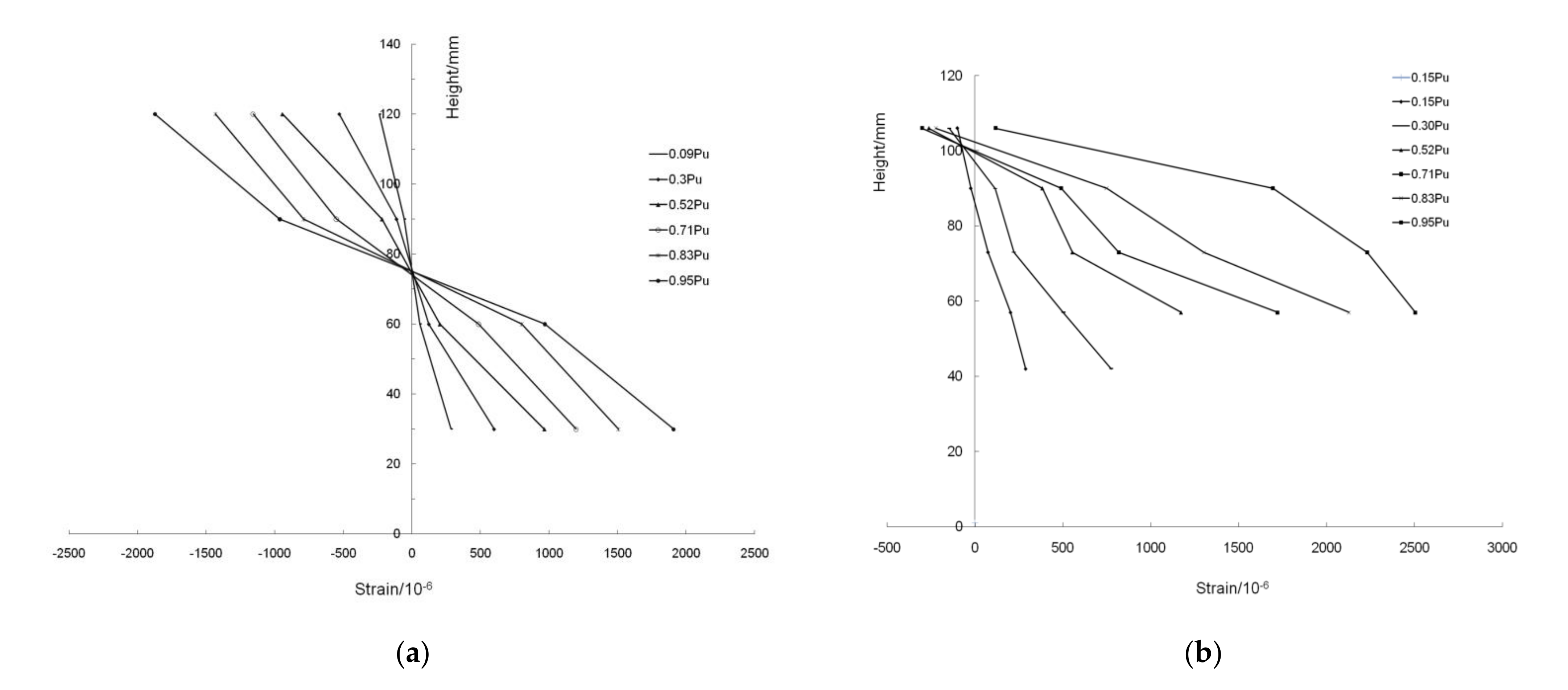
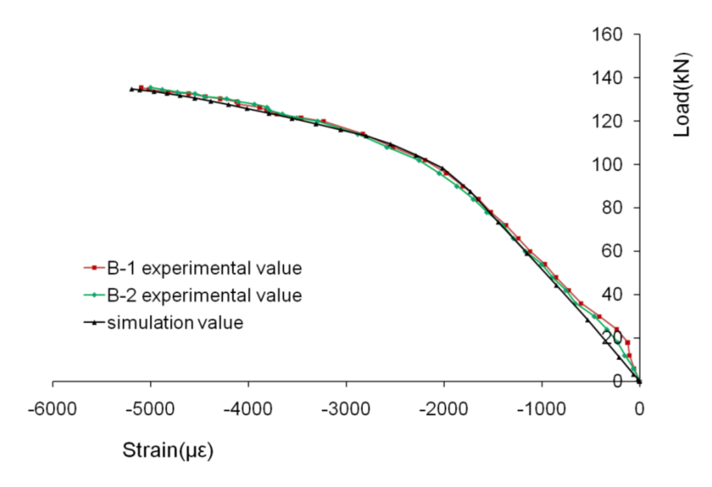
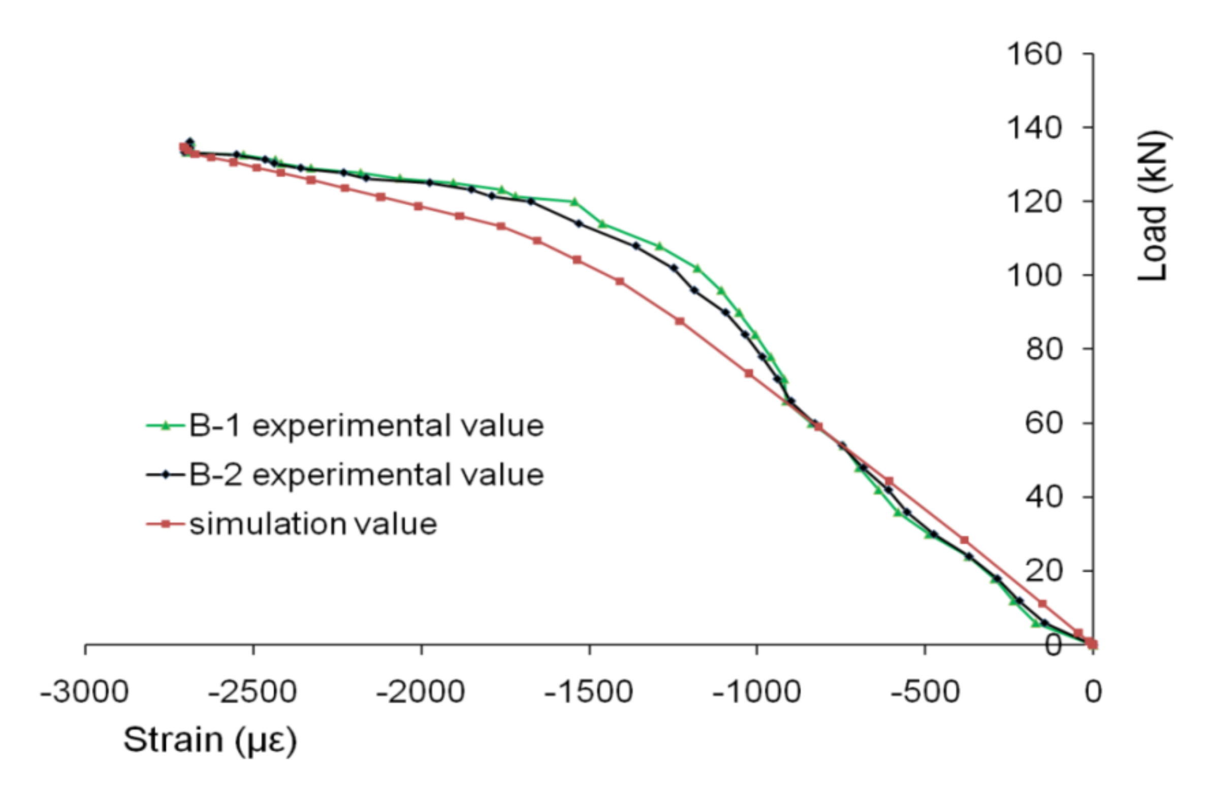
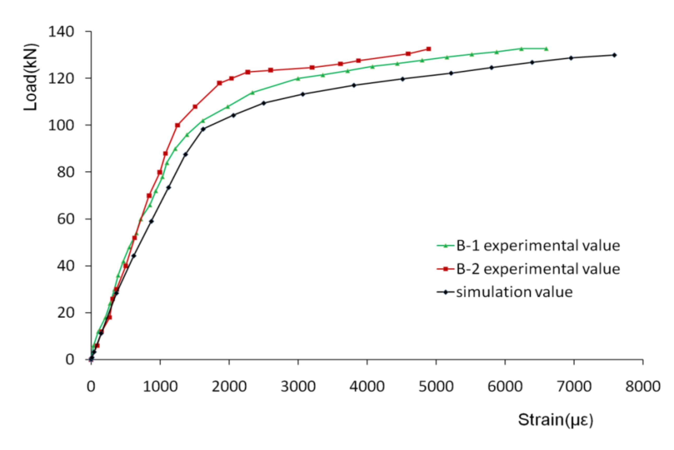
2.5.2. Load-Strain Relationship
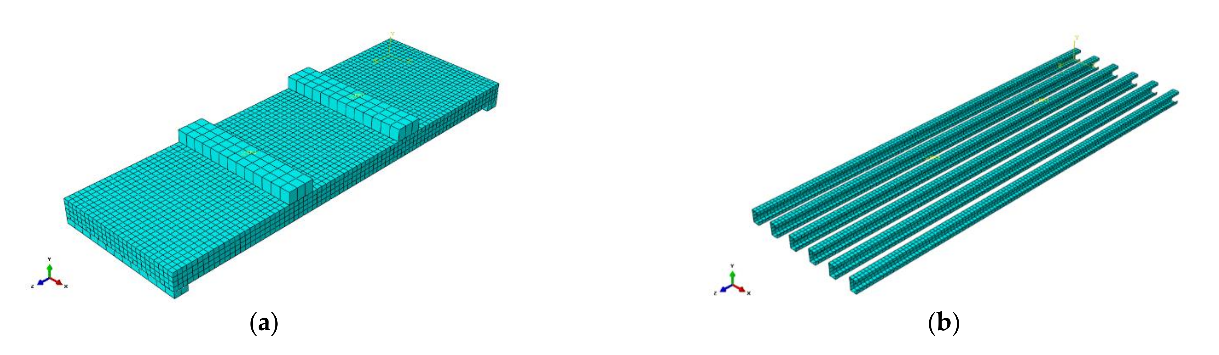
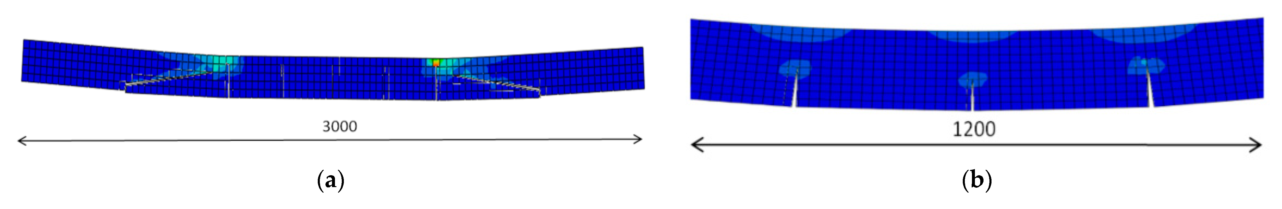
3. Finite Element Modeling
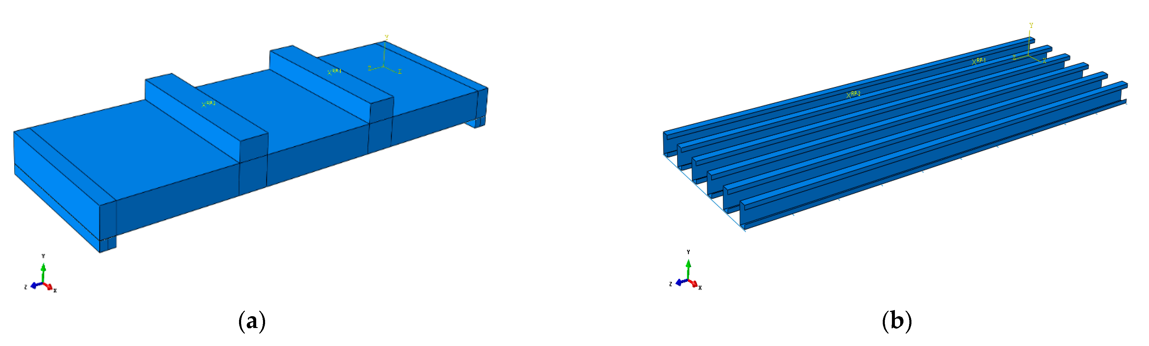
3.1. Material Model and Dimension of the Model
- x—is the ratio of the strain to the maximum strain;
- y—is the ratio of the stress to the compressive strength of foam concrete.
- σ—stress of the steel;
- ε—strain of the steel;
- Es—Young’s modulus;
- fy—yield stress;
- εy—yield strain is the limit value of strain.
3.2. Model Validation
4. Parametric Studies Using FE Model
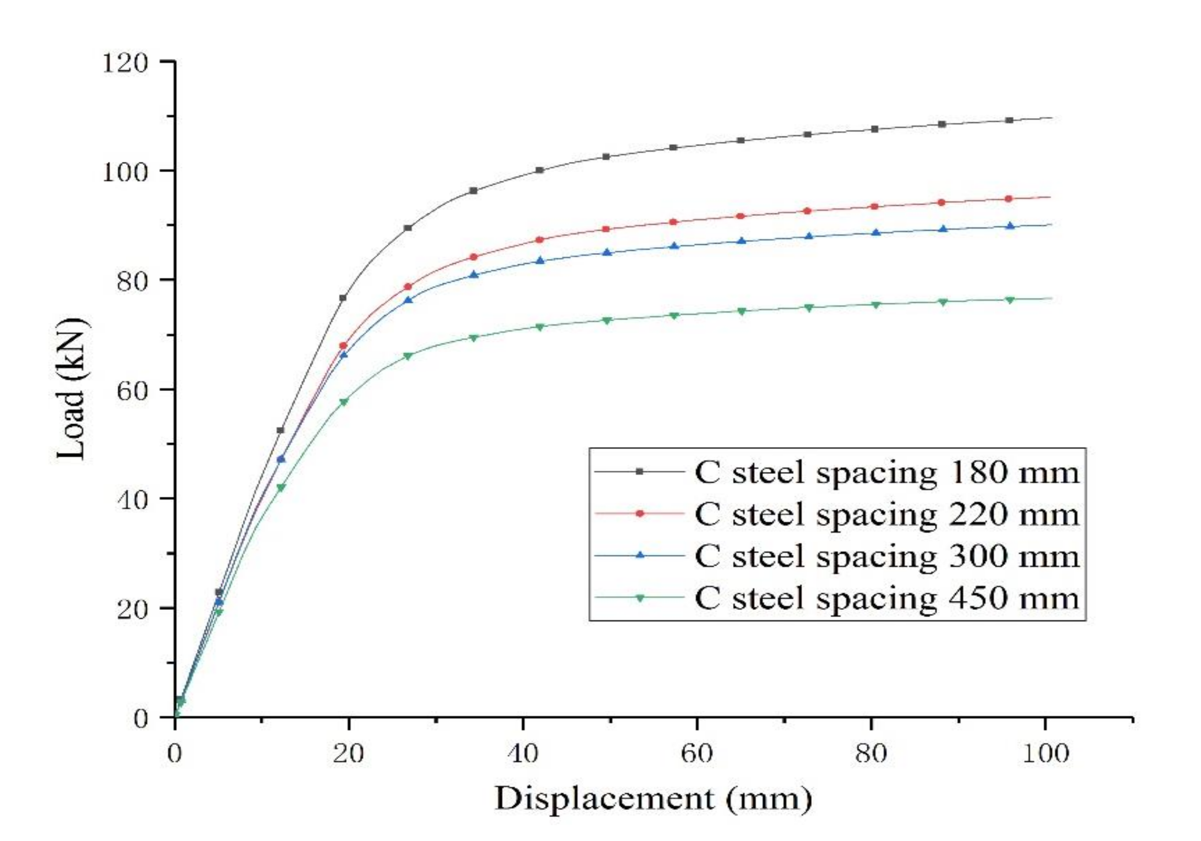
4.1. Effect of the Space of the Cold-Formed Thin-Walled CSteelChannels
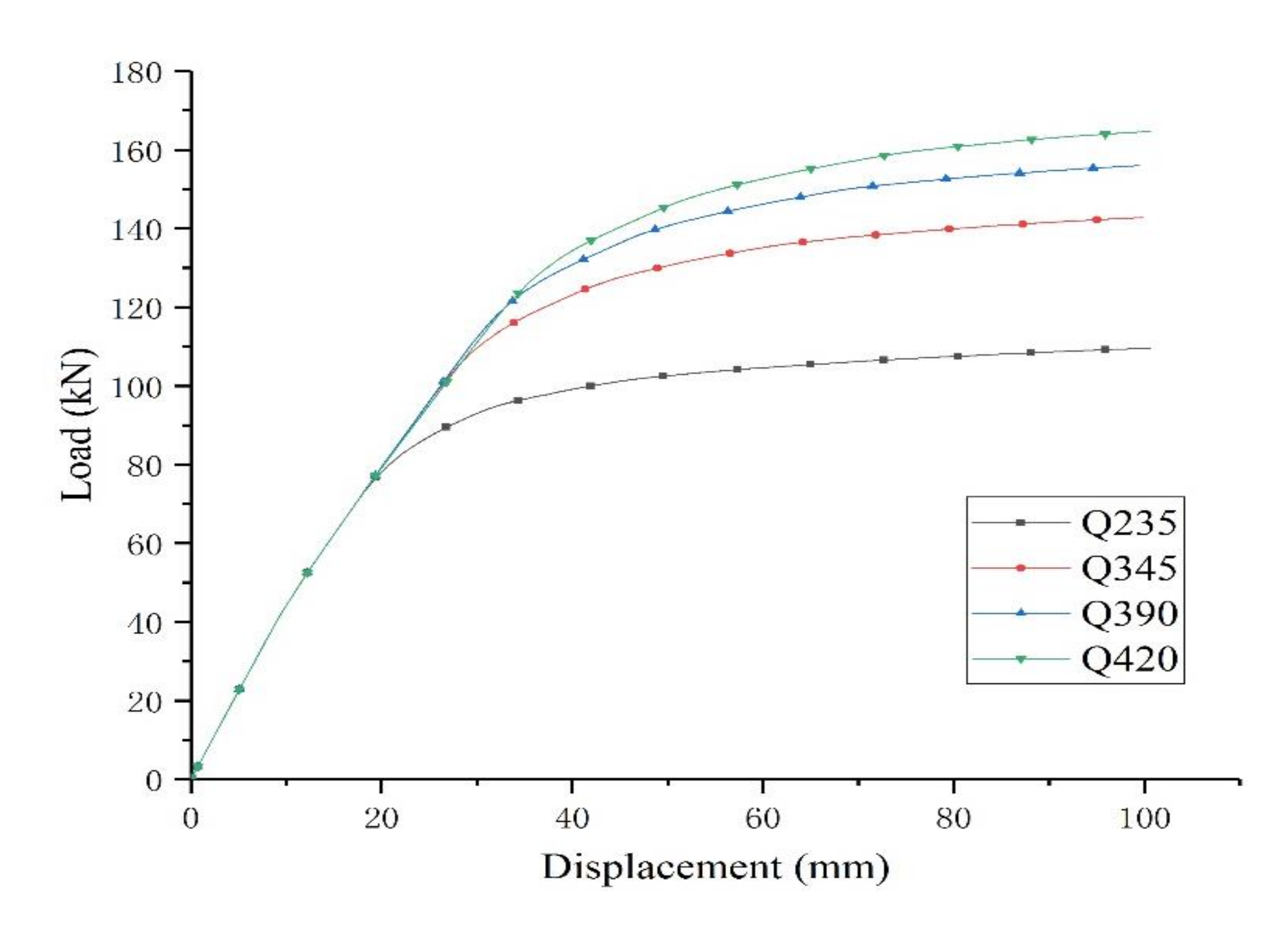
4.2. Effect of the Grade of the Cold-Formed Thin-Walled C Steel Channels
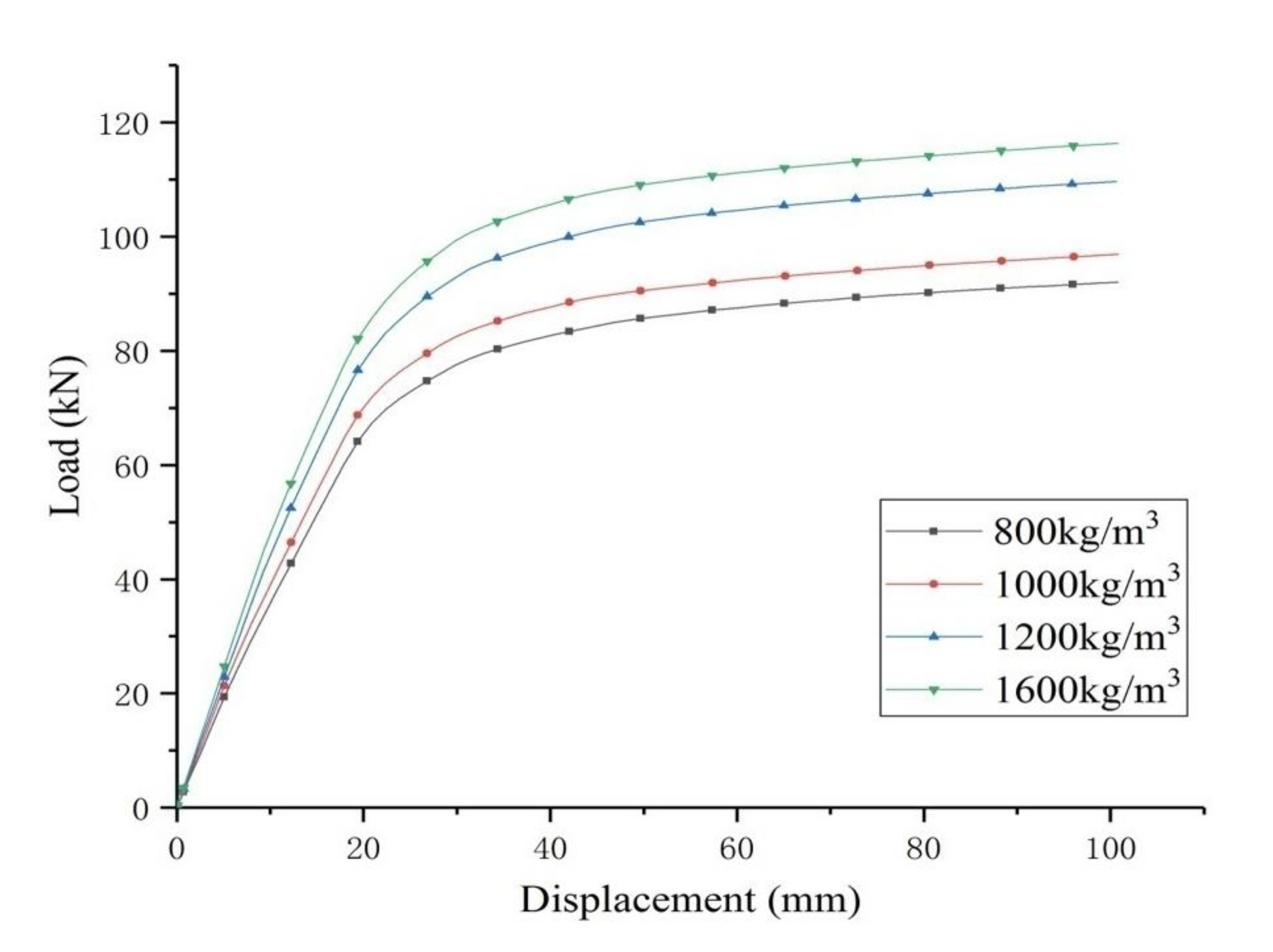
4.3. Effect of the Compressive Strength of the Foam Concrete
5. Conclusions
- The test shows that the composite floor formed by foamed concrete and cold-formed thin-walled C steel channels shows good bearing capacity and deformation capacity, but the stiffness of the composite floor is relatively small. When reaching the limit state, the upper and lower flanges and part of the webs of the cold-formed thin-walled C steel channels have reached the yield strength, and the plastic deformation of the composite floor has been fully developed.
- The comparison of the load-deflection curve and load-strain curve shows that the simulation results are in good agreement with the test results.
- The smaller the spacing of cold-formed thin-walled C steel channels, that is, the greater the steel content, the higher the load-bearing capacity of the composite floor.
- The higher the compressive strength of the foamed concrete, the higher the bearing capacity of the composite floor slab, while the stiffness increases.
- The increase of the steel strength of the cold-formed thin-walled C steel channels can increase the bearing capacity of the composite floor, but it has almost no effect on the stiffness of the composite floor.
Author Contributions
Funding
Institutional Review Board Statement
Informed Consent Statement
Data Availability Statement
Conflicts of Interest
References
- Liu, D.; Wang, F.; Fu, F.; Wang, H. Experimental research on the failure mechanism of foam concrete with C-channel embedment. Comput. Concr. 2017, 20, 263–273. [Google Scholar]
- Liu, D.; Wang, F.; Fu, F. Experimental Research on the Shear Connectors in Foam Concrete with C-channel Embedment. Int. J. Concr. Struct. Mater. 2018, 12, 51. [Google Scholar] [CrossRef]
- Mydin, M.A.O.; Wang, Y.C. Elevated-temperature thermal properties of lightweight foamed concrete. J. Constr. Build. Mater. 2011, 25, 705–716. [Google Scholar]
- Ibrahim, W.; Jamaluddin, N.; Irwan, J.M.; Ramadhansyah, P.J.; SurayaHani, A. Compressive and flexural strength of foamed concrete containing polyolefin fibers. Adv. Mater. Res. 2014, 911, 489–493. [Google Scholar] [CrossRef] [Green Version]
- Yan, J.B.; Guan, H.N.; Wang, T. Numerical studies on steel-UHPC-steel sandwich beams with novel enhanced C-channels. J. Constr. Steel Res. 2020, 170, 106070. [Google Scholar] [CrossRef]
- Sohel, K.M.A.; Richard, L.J.Y.; Yan, J.B.; Zhang, M.H.; Chia, K.S. Behavior of Steel–Concrete–Steel sandwich structures with lightweight cement composite and novels hear connectors. Compos. Struct. 2012, 94, 3500–3509. [Google Scholar] [CrossRef]
- Yue, L.; Bing, C. New type of super-lightweight magnesium phosphate cement foamed concrete. J. Mater. Civ. Eng. 2015, 27, 04014112. [Google Scholar] [CrossRef]
- Ikponmwosa, E.; Falade, F.; Fapohunda, C.; Akinniyi, T.; Olori, K. Effect of foam concentration on structural characteristics of steel reinforced aerated concrete beams. Pac. J. Sci. Technol. 2014, 15, 32–46. [Google Scholar]
- KunhanandanNambiar, E.K.; Ramamurthy, K. Models relating mixture composition to the density and strength of foam concrete using response surface methodology. Cem. Concr. Compos. 2006, 7, 752–760. [Google Scholar]
- Jones, M.R.; Carthy, A.M. Heat of hydration in foamed concrete: Effect of mix Constituents and Plastic density. Cem. Concr. Res. 2006, 36, 1032–1041. [Google Scholar] [CrossRef]
- Kearsleya, E.P.; Wainwright, P.J. The effect of high flyash content on the compressive strength of foamed concrete. Cem. Concr. Res. 2001, 31, 105–112. [Google Scholar] [CrossRef]
- Hashimoto, A.; Hayashi, S.; Yamamoto, S.; Chujo, H. Process of Continuous Manufacture of Light-Weight Foamed Concrete. US Patent US4057608, 8 November 1977. [Google Scholar]
- American Ironand Steel Institue. AISI S100-16, North American Specification for the Design of Cold-Formed Steel Structural Members; draftedition; CSA GROUP: Toronto, ON, Canada, 2001. [Google Scholar]
- GB50018-2002. Technical Code of Cold-Formed Thin-Wall Steel Structures. Chinese Standard; China Planning Press: Beijing, China, 2002. [Google Scholar]
- Wright, H.D.; Evans, H.R. A folded plate method of analys is for profiled steel sheeting in composite floor construction. Thin-Walled Struct. 1987, 5, 21–37. [Google Scholar] [CrossRef]
- Helmut, B.; Ingeborg, S. Zur Berechnungdurchlaufender Verbunddecken. Calculation of continuous composite slabs. Stahlbau 1997, 66, 416–426. [Google Scholar]
- Elghazoul, A.Y.; Izzuddin, B.A. Realistic Modeling of Composite and Reinforced Comcrete Floor Slabsunder Extreme Loding. J. Struct. Eng. 2004, 130, 1985–1996. [Google Scholar] [CrossRef] [Green Version]
- Crisinel, M.; Marimon, F. A new simplified method for the design of composites labs. J. Constr. Steel Res. 2004, 60, 481–491. [Google Scholar] [CrossRef]
- Jeong, Y.-J. Simplified model to predict partial-interactive structura lperformance of steel-concrete composites labs. J. Constr. Steel Res. 2008, 64, 238–246. [Google Scholar] [CrossRef]
- Fu, F. Design and Analysis of Tall and Complex Structures; Elsevier: Oxford, UK, 2018; pp. 1–304. [Google Scholar]
- Fu, F. Advanced Modelling Techniques in Structural Design; JohnWiley & Sons: Oxford, UK, 2015; ISBN 978-1-118-82543-3. [Google Scholar]
- Fu, F. Structural Analys is and Design to Prevent Disproportionate Collapse; CRCPress: Boca Raton, FL, USA, 2016; ISBN 978-1-4987-8820-5. [Google Scholar]
- Deng, X.-F.; Liang, S.-L.; Fu, F.; Qian, K. Effects of High-Strength Concrete on Progressive Collapse Resistance of Reinforced Concrete Frame. J. Struct. Eng. 2020, 146, 04020078. [Google Scholar] [CrossRef]
- Guo, L.; Liu, Y.; Fu, F.; Huang, H. Behavior of axially loaded circular stain less steel tube confined concrete stubcolumns. Thin-Walled Struct. 2019, 139, 66–76. [Google Scholar] [CrossRef]
- Qian, K.; Liang, S.-L.; Fu, F.; Fang, Q. Progressive collapse resistance of precast concrete beam-column sub-assemblages with high-performance dry connections. Eng. Struct. 2019, 198, 109552. [Google Scholar] [CrossRef]
- Wang, L.; Shen, N.; Zhang, M.; Fu, F.; Qian, K. Bond performance of Steel-CFRP barre in forced coral concrete beams. Constr. Build. Mater. 2020, 245, 118456. [Google Scholar] [CrossRef]
- Fu, F.; Lam, D.; Ye, J. Moment resistance and rotation capacity of semi-rigid composite connections with precast hollow core slabs. J. Constr. Steel Res. 2010, 66, 452–461. [Google Scholar] [CrossRef]
- Fu, F. Fire induced progressive collapse potential assessment of steel framed buildings using machine learning. J. Constr. Steel Res. 2020, 166, 105918. [Google Scholar] [CrossRef]
- Fu, F.; Parke, G.A.R. Assessment of the Progressive Collapse Resistance of Double-Layer Grid Space Structures Using Implicit and Explicit Methods. Int. J. Steel Struct. 2018, 18, 831–842. [Google Scholar] [CrossRef]
- GB/T700-2006. Carbon Structure Steels, Chinese Standard; Standards Press of China: Beijing, China, 2007. [Google Scholar]
- Hong-Gun, P.; Choi, K.K.; Wight, J.K. Strain-based shear strength model for slender beams without web reinforcement. ACI Struct. J. 2006, 103, 783–793. [Google Scholar]
- De Domenico, D.; Ricciardi, G. Shear strength of RC beams with stirrups using an improved Eurocode 2 truss model with two variable-inclination compression struts. Eng. Struct. 2019, 198, 109359. [Google Scholar] [CrossRef]
- Liu, D.; Wang, F.; He, M. Experimental research for constitutional relationship of foam concrete under uniaxial compressions. Archit. Technol. 2016, 47, 758–760. [Google Scholar]


| Density (kg/m3) | Weight of Fly Ash (kg) | Weight of Cement (kg) | Weight of Water (kg) | Weight of Foam Agent (kg) | Volume of Foam (m3) |
|---|---|---|---|---|---|
| 1200 | 200 | 800 | 400 | 0.32 | 0.2916 |
| Material | Density (kg/m3) | Compressive Strength/MPa | Tensile Strength/MPa | Young’s Modulus/MPa | Poisson’s Ratio |
|---|---|---|---|---|---|
| C-channel | 7800 | 300 | 300 | 2.05 × 10⁵ | 0.30 |
| Foam concrete | 1200 | 17.8 | 2.4 | 2.73 × 10³ | 0.20 |
| Testing Stages | Mid-Span Deflection from FE Model (mm) | Mid-Span Deflection from Test (mm) | Simulation Value/Test Value |
|---|---|---|---|
| Stage 1 | 5.51 | 5.99 | 0.92 |
| Stage 2 | 25.65 | 25.55 | 1.003 |
| Stage 3 | 85.806 | 82 | 1.046 |
| Model Number | Ratio of C-Channels % | Tensile Strength of Steel MPa | Density of Foam Concrete kg/m3 | Compressive Strength of Foam Concrete MPa |
|---|---|---|---|---|
| J-1 | 1.92 | 235 | 1200 | 17.0 |
| J-2 | 1.60 | 235 | 1200 | 17.0 |
| J-3 | 1.28 | 235 | 1200 | 17.0 |
| J-4 | 0.96 | 235 | 1200 | 17.0 |
| Density kg/m3 | Young’s Modulus MPa | Poisson’s Ratio | Compressive Strength MPa | Tensile Strength MPa |
|---|---|---|---|---|
| 800 | 1.75 × 10³ | 0.2 | 7.8 | 0.52 |
| 1000 | 2.29 × 10³ | 0.2 | 10.2 | 0.68 |
| 1200 | 2.73 × 10³ | 0.2 | 17.0 | 1.13 |
| 1600 | 3.29 × 10³ | 0.2 | 21.5 | 1.43 |
Publisher’s Note: MDPI stays neutral with regard to jurisdictional claims in published maps and institutional affiliations. |
© 2021 by the authors. Licensee MDPI, Basel, Switzerland. This article is an open access article distributed under the terms and conditions of the Creative Commons Attribution (CC BY) license (https://creativecommons.org/licenses/by/4.0/).
Share and Cite
Liu, D.; Fu, F.; Liu, W. Structural Behavior of Composite Floor System Using Cold-Formed Thin-Walled C Steel Channel Embedded Foam Concrete. Appl. Sci. 2021, 11, 9888. https://doi.org/10.3390/app11219888
Liu D, Fu F, Liu W. Structural Behavior of Composite Floor System Using Cold-Formed Thin-Walled C Steel Channel Embedded Foam Concrete. Applied Sciences. 2021; 11(21):9888. https://doi.org/10.3390/app11219888
Chicago/Turabian StyleLiu, Dianzhong, Feng Fu, and Wanjuan Liu. 2021. "Structural Behavior of Composite Floor System Using Cold-Formed Thin-Walled C Steel Channel Embedded Foam Concrete" Applied Sciences 11, no. 21: 9888. https://doi.org/10.3390/app11219888