Article

A Nondestructive Method of Measuring Zebrafish Adipose Tissue Based on Micro-Computed Tomography (Micro-CT)

The Analysis and Testing Center of Institute of Hydrobiology, Chinese Academy of Sciences, Wuhan 430072, China
*
Authors to whom correspondence should be addressed.
Appl. Sci. 2021, 11(22), 10510; https://doi.org/10.3390/app112210510
Submission received: 15 October 2021 / Revised: 2 November 2021 / Accepted: 3 November 2021 / Published: 9 November 2021
(This article belongs to the Section Applied Biosciences and Bioengineering)

Abstract

:

Featured Application

The detection of fish body fat distribution and content is key in the study of lipid metabolism. Our study established an imaging technology for the rapid and nondestructive detection of the fat distribution and content of fish by micro-CT.

Abstract

Due to problems such as unbalanced intake of nutrients or excessive intake of energy, cultured fish accumulate fat in places such as the abdominal cavity, liver, and muscle, resulting in fatty liver, reducing the quality of fish meat, and even causing many fish deaths, resulting in losses to aquaculture production. Therefore, research on lipid metabolism in fish is important and has attracted increasing attention. The detection of fish body fat distribution and content is a key to such research. The existing methods for detecting fat distribution and content in fish have limitations, such as cumbersome procedures and damage to fish tissues, and thus, is imperative to develop a simple, fast, nondestructive fat detection technology. Taking zebrafish as the research material, this study established an imaging technology for the rapid and nondestructive detection of the fat distribution and content of fish by micro-computed tomography (micro-CT), optimized the fat CT-scanning method, determined the steps of fat quantitation in the CTAn data processing software, and constructed a three-dimensional (3D) model of zebrafish adipose tissue. This technology reveals the distribution of fish adipose tissue in an all-round way, and thus, it will play an important role in the study of lipid metabolism in fish.

1. Introduction

Lipids are important energy substances, nutrients, and structural materials in organisms. In the aquaculture industry, due to problems such as improper feeding or uneven nutrient composition of feed, a large amount of fat can accumulate in the liver, muscle, abdominal cavity, and other tissues of fish, resulting in fatty liver [1], low meat quality, weakened anti-stress ability [2], and high incidence of various diseases in cultured fish [3,4]; furthermore, in serious situations, many deaths and great economic losses to the aquaculture industry can occur [5]. In medicine, disordered lipid metabolism induces many major diseases, including Alzheimer’s disease, obesity, type 2 diabetes mellitus [6], atherosclerosis, heart disease [7], and tumors [8]. Therefore, in recent years, research on the mechanism of fat accumulation in fish has also attracted increasing attention [9,10]. The zebrafish model is one of the most important experimental animal models in modern life science research [11] and has been widely used in various research fields [12,13,14,15,16]. Zebrafish are characterized by small size, rapid growth, and strong reproductive capacity. They can produce many offspring in a short time. Their growth and metabolic process are easy to control manually, and their aquaculture cost is low. Therefore, zebrafish are a suitable object for lipid metabolism research [17,18,19].
Micro-computed tomography (micro-CT) is a nondestructive three-dimensional (3D) imaging technology. With micro-CT, the internal microstructure of the sample can be clearly observed without destroying the sample, and the relevant parameters can be quantitatively calculated. Therefore, micro-CT has been widely used in life science research. The principle is that when the X-ray passes through the sample, each part of the sample may absorb a different amount of X-rays (absorption contrast) and have different phase shifts (phase contrast). The X-ray source emits X-rays, which penetrate the sample and finally form an image on the X-ray detector. The X-ray absorption and phase shift are related to the atomic numbers of the constituent elements of the sample. Generally, the heavier the element, the greater the X-ray absorption and phase shift [20]. Table 1 lists the X-ray properties of the main constituent elements of biological tissue under 8-keV X-irradiation. The data are from the automatic query tool for the X-ray properties of elements on the website of the Lawrence Berkeley National Laboratory in the United States [21]. Table 2 lists the mass-weighted averages of the element proportions and the atomic numbers of biological tissues calculated by mass percentage [22].
In Table 1, under the same energy, the main constituent elements C, H, O, N, and Ca of biological tissue have different f1 and f2 values. It can be seen from Table 2 that for the two main soft tissue types in organisms, fat and muscle, the contents of the two main components C and O in fat are 57.3 and 30.3%, respectively, while their contents in muscle are 12.3 and 72.9%. The contents of C and O in bone tissue are 27.8 and 41%, with 14.7% Ca. There is a difference in the element composition of adipose tissue, muscle tissue, and bone tissue, which make them absorb (absorption contrast) and phase-shift X-rays differently (phase contrast). Therefore, different light- and dark-gray images can be obtained from micro-CT images. Figure 1 shows a micro-CT image of a zebrafish abdomen. According to different gray levels, adipose tissue, non-adipose tissue, and bone tissue can be distinguished. The adipose tissue is represented by the dark-gray area. Taking zebrafish as a model organism, this paper explores the application of micro-CT technology for fat detection in fish. Through the 3D imaging of fat in zebrafish and the calculation of their fat content, we provide a new technical means for fat detection in fish.

2. Materials and Methods

2.1. Experimental Materials

The zebrafish (Brachydanio rerio var) individual was from the China Zebrafish Resource Center, Institute of Hydrobiology, Chinese Academy of Sciences.

2.2. Sample Preparation

The zebrafish used was 3.5 cm long (Figure 2A). After freezing and killing, the zebrafish was immediately put into neutral formalin for fixation. Before scanning, the zebrafish was taken out of the fixation solution, and the fixation solution on the surface of the fish was wiped off with a paper towel. To prevent deformation of the zebrafish due to water loss during scanning, the fish body was wrapped in a plastic film and then fixed on the sample table with medical tape for scanning (Figure 2B).

2.3. Optimization of CT-Scanning Imaging Parameters

The SkyScan 1276 imaging system for small live animals (Bruker, Karlsruhe, Germany) was used in this research. Two experiments were conducted to optimize the CT-scanning parameters of the zebrafish (see Table 3). The first experiment was conducted to compare the imaging quality of adipose tissue signals at 2000 and 4000 pixels. The second experiment was performed to compare the imaging effects of 180° and 360° scanning.

2.4. Data Reconstruction

The scanned data were reconstructed in the NRecon 1.7.4.2 software. In the reconstruction process, a% beam-hardening correction of 30, a ring artifact correction of 3, and a Gaussian smoothing of 5 were used.

2.5. Data Processing

The CTAn1.20.3.0 data processing software was used for image processing and fat quantitation. In this procedure, we focused on the fat content of the trunk of the fish, which we defined as going from the first spine to the base of the gluteal fin. In CTAn, we first set the trunk as the analysis area. The selected area was a clearly visible image, and the green area was not included (Figure 3). After selecting the analysis position, according to the different gray-level information of each tissue, the adipose tissue was binarily segmented. In the binary selection preview options, different upper and lower thresholds could be set to preview the segmented adipose tissue and determine the appropriate threshold range. The threshold range of the adipose tissue selected in this experiment was 30–60 (Figure 4).
The red area in Figure 4B represents the selected adipose tissue. In addition to the adipose tissue in the fish, the surface of the fish was also covered with red. This was due to the partial volume effect, which caused the surface of the sample to be slightly brighter than the background, as bright as the selected threshold of adipose tissue, and thus, it was identified as adipose tissue, which seriously lowered the accuracy of the 3D image generation and quantitative calculation of adipose tissue. In the custom processing preview options of the CTAn analysis software, a series of custom operation commands was used to transform the shape of the fish, aiming to eliminate the selected red area on the outermost layer (Figure 5).
Through a series of custom operations, the adipose tissue was distinguished in the image inside ROI (Region of Interest) panels in Figure 5. First, a white mesh corresponding to the whole mouse outline was generated. For this, all soft tissues were binarized using the threshold that was previously found for all soft tissues, using a global threshold plug-in. To remove white dots (noise speckles) around the outline, the despeckle plug-in SWEEP in 3D was used. Next, a ROI shrink-wrap function was applied in 2D to limit the ROI to the outside borders of the fish. To make sure the fat selection did not include any parts of the fish skin, a small erosion function was applied, only a few pixels away from the endocortical surface. Then, the image was reloaded in order to be able to save the region of interest from the region of the ROI. Finally, the reloaded image was binarized with the adipose tissue threshold range. The resulting image was a binary image that contained the adipose tissue. The 3D operation was run through custom processing in CTAn to calculate the volume and thickness of adipose tissue (Figure 6), and the volume and thickness data of the adipose tissue were saved for later construction of the 3D model of adipose tissue.

2.6. Construction of the 3D Model of Adipose Tissue

Two 3D viewing software applications, CTvox3.3.1 and CTvol2.3.2.0 from Bruker, were used to construct the 3D model of fish adipose tissue. The CTvox software provides two kinds of 3D model construction effects. One involves the performance of color rendering according to the gray-level information inside the sample in order to assign different colors to each tissue. The other involves the performance of color rendering to different thicknesses of adipose tissue according to the thickness information of the adipose tissue saved by the 3D operations of the CTAn software. The CTvol software can construct a 3D model of adipose tissue according to the volume information of adipose tissue saved by the 3D operations of the CTAn software.

3. Results

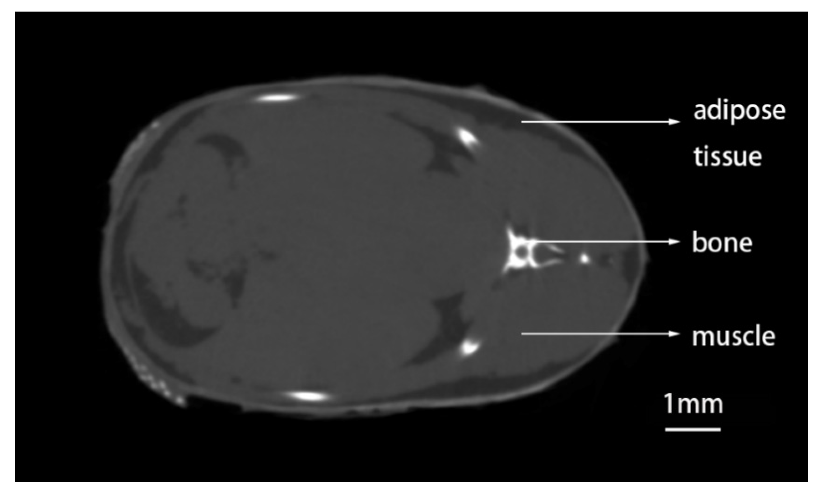
3.1. Method to Detect Adipose Tissue in Zebrafish by CT Scanning

The fat imaging results with 2000 and 4000 pixels are shown in Figure 7A,B, respectively. Comparing them, we found that the shape and distribution of adipose tissue was most clearly imaged with 4000 pixels, but the whole image had high noise and poor smoothness, which was not conducive to threshold segmentation of adipose tissue in later processing steps. With 2000 pixels, the shape and distribution of adipose tissue were also clearly imaged, and the overall noise of the image was low, with a distinct contrast between the adipose tissue and other tissues, which was conducive to the threshold segmentation and quantitative calculation of adipose tissue that we needed to perform in postprocessing. Therefore, the scanning effect of 2000 pixels was better than that of 4000 pixels.
Figure 7C,D show the 180° scan and 360° scan results with 2000 pixels, respectively. In the 180° scan, the black artifacts around the different levels of bone not only affected the imaging quality but could also be mistaken for adipose tissue in the threshold segmentation of adipose tissue during postprocessing, which would have made the quantitative calculation of the adipose tissue less accurate. In the 360° scan, the black artifacts around the bone were greatly reduced, the boundaries of bone, fat, muscle, and other tissues were clear, and the imaging quality was high. All these factors were conducive to the quantitative calculation of adipose tissue in postprocessing.

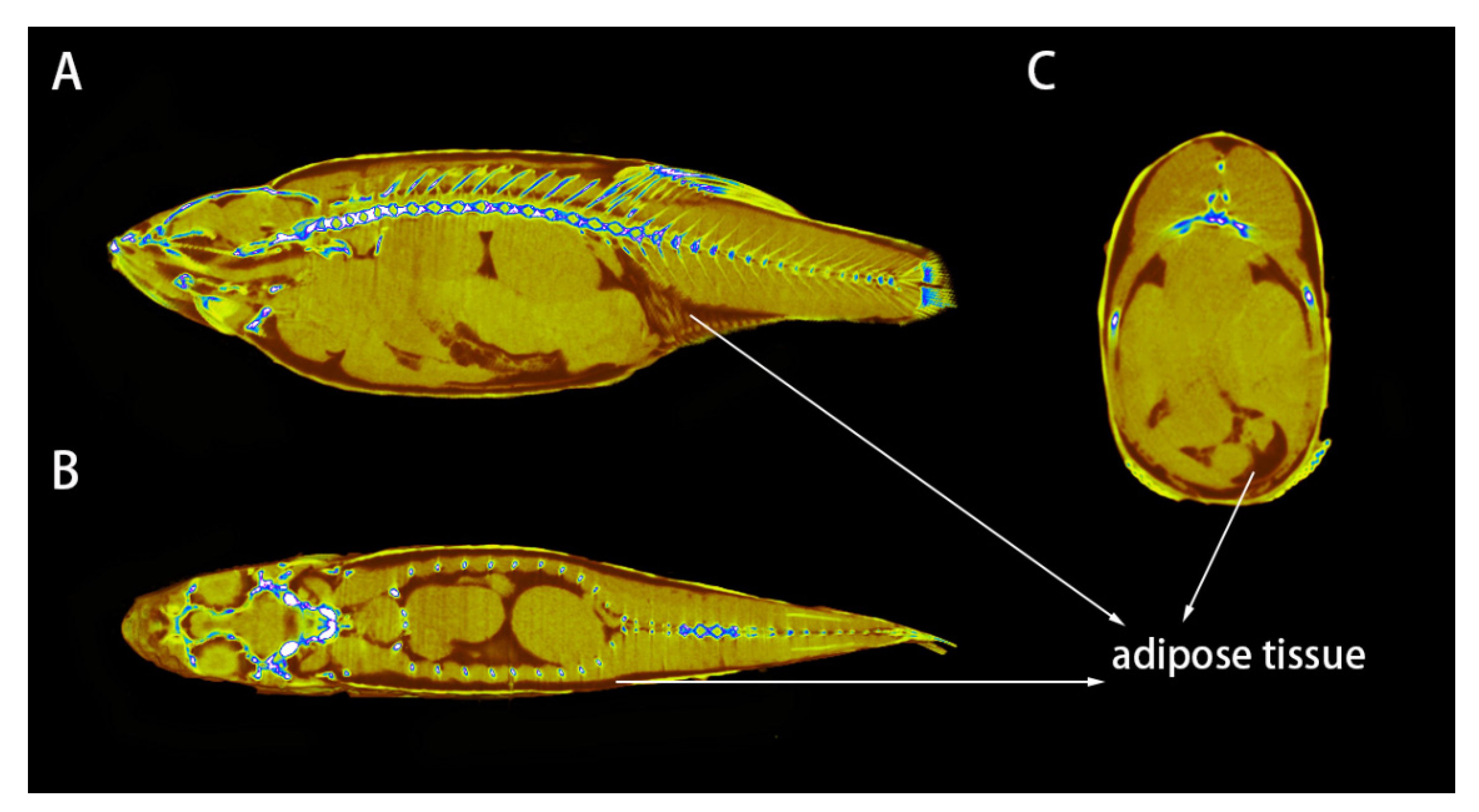
3.2. Distribution of Adipose Tissue in Zebrafish

In the DataViewer 2D viewing software, the samples were observed in simulated 2D slices from any point in the sample along the X, Y, and Z axes (Figure 8). In the CTvox 3D viewing software, color rendering could be performed based on the gray information in the sample, assigning different colors to adipose tissue, muscle tissue, and bone tissue, and cutting was possible in any direction in 3D space to observe the internal structure of the sample (Figure 9). Through the two observation methods depicted in Figure 8 and Figure 9, we found that the adipose tissue of zebrafish was mainly in the head, subcutaneously on both sides of the body and the back, in the abdomen, and on both sides of the swim bladder.

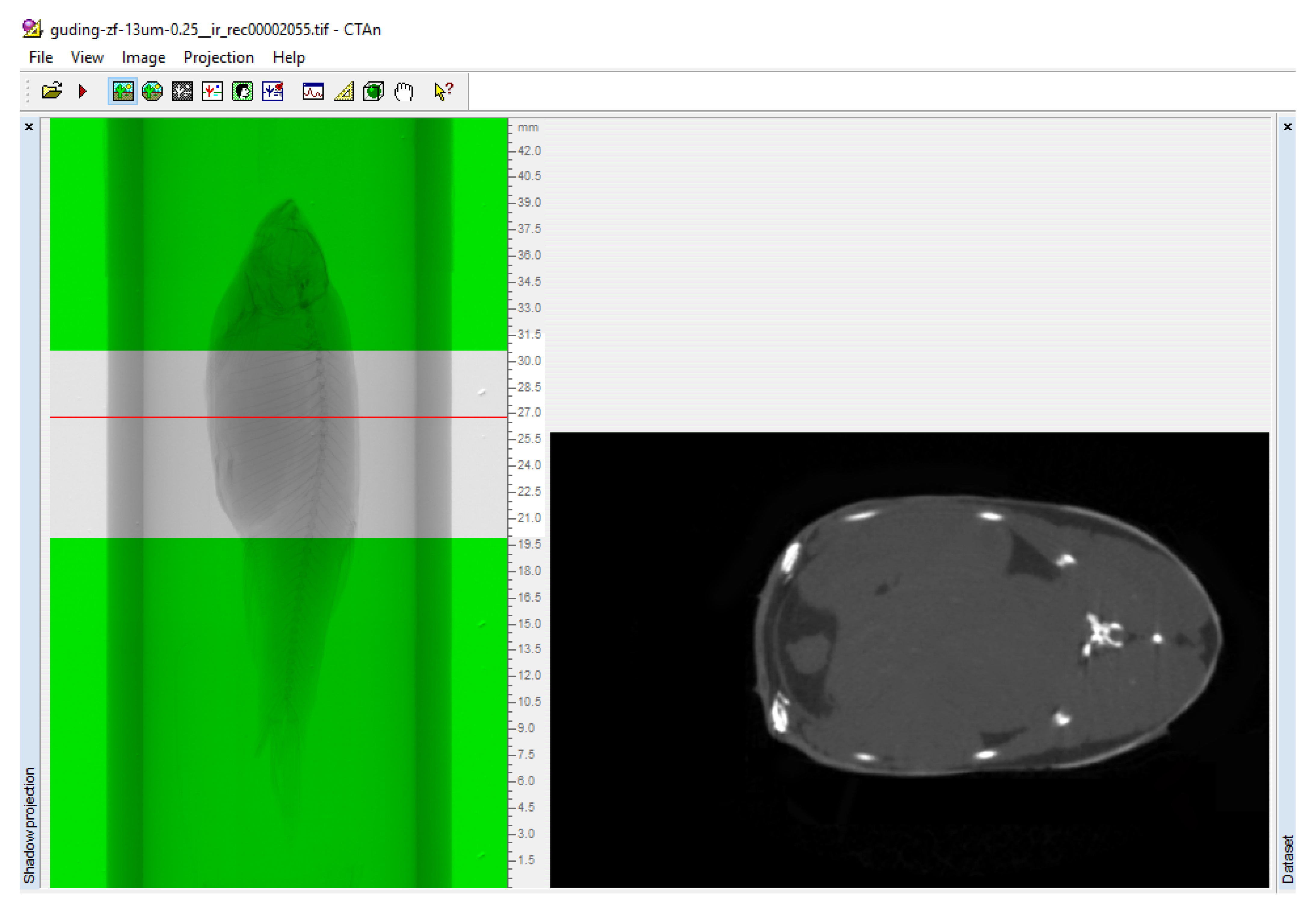
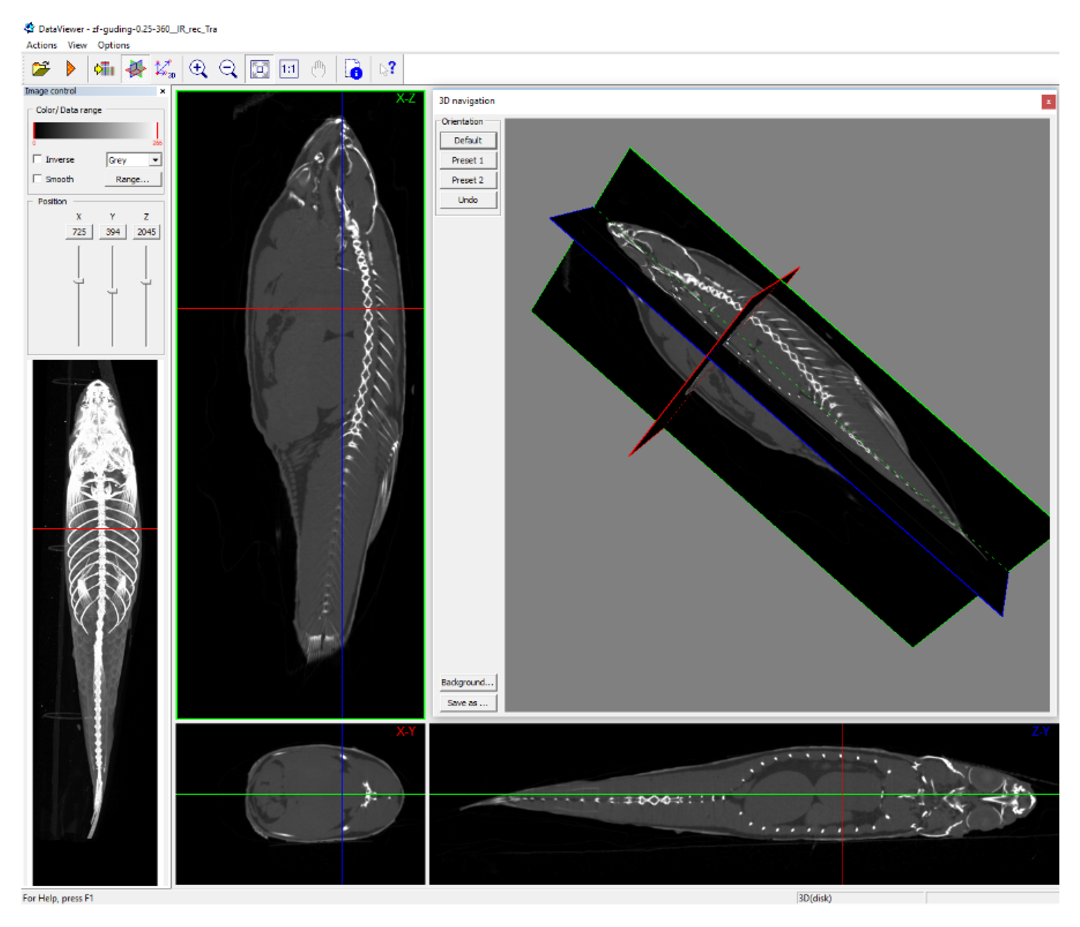
3.3. Scanning the Standard Plane of Trunk Adipose Tissue

Appropriate visualization of the fat localization in the fish is very useful in bioenergetics for the study of energy allocation, but also in the assessment of fish quality. Traditionally, fat is extracted from either a complete fillet that has been macerated, or from specific areas defined as standard cuts. Therefore, the fat localization is lost by traditional techniques in fish quality assessment. Fish of different species have variable body shapes and internal structures as well as varied energy allocation in different nutritional stages, which results in differential distribution of fat in different tissues. In this experiment, we specified the scanning plane of the entire spine as the longitudinal standard scanning plane to provide a standard. Figure 10A shows a continuous sagittal scan of the zebrafish trunk with a thickness of 0.2 mm. Figure 10B shows the result of the calculation of the area of adipose tissue in different scanning planes. As seen from Figure 10, the shape and distribution of adipose tissue are different when different planes are used, and the area of adipose tissue is different in different scanning planes, indicating that the adipose tissue in the zebrafish is not symmetrically distributed around the spine. The cross-sectional view is also often for fish scanning images [23,24], and it is more difficult to formulate a standard plane for transverse scanning than for longitudinal scanning. The position of the fin was recommended as the standard plane for transverse scanning [24]. In this experiment, we specified the base of the pelvic fin as the standard plane for transverse scanning, as shown by the red line in Figure 11A. Here, the transverse scanning planes divided the fish body into multiple slices of 0.35 mm thickness, as often used for fish quality evaluation in food science research. This experiment shows that fish slices at different cross-sectional positions contained different fat contents, but there was little difference in fat content between different fish slices.

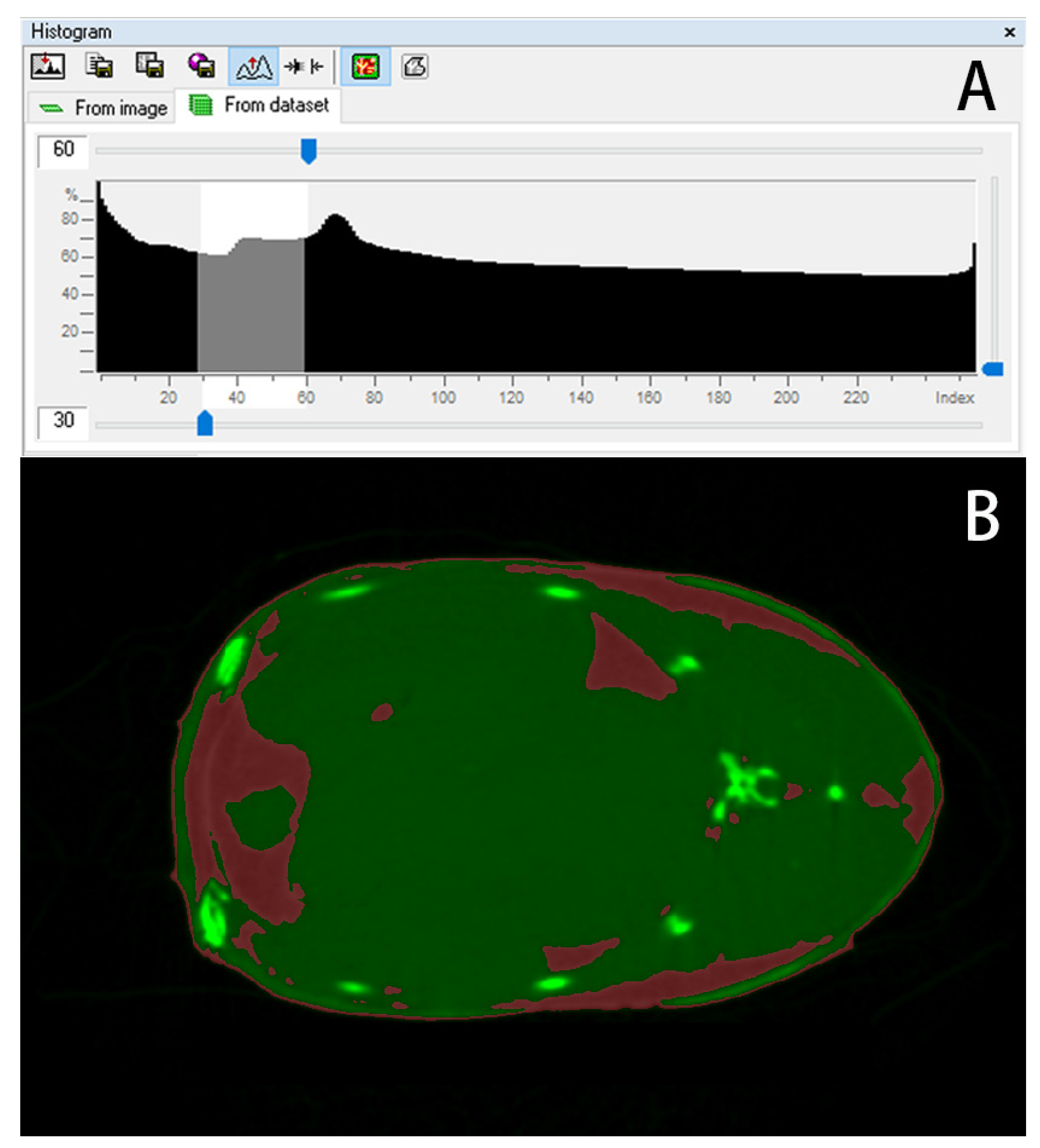
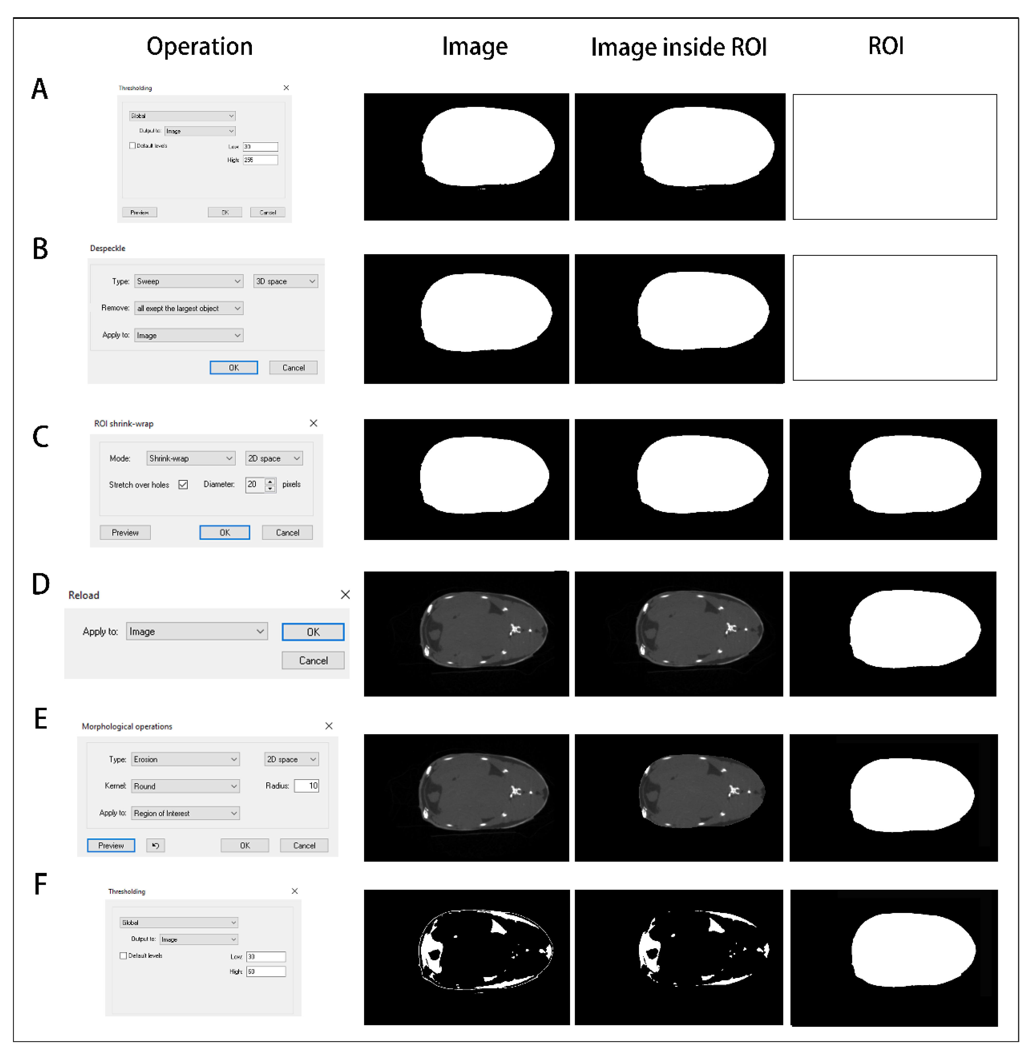
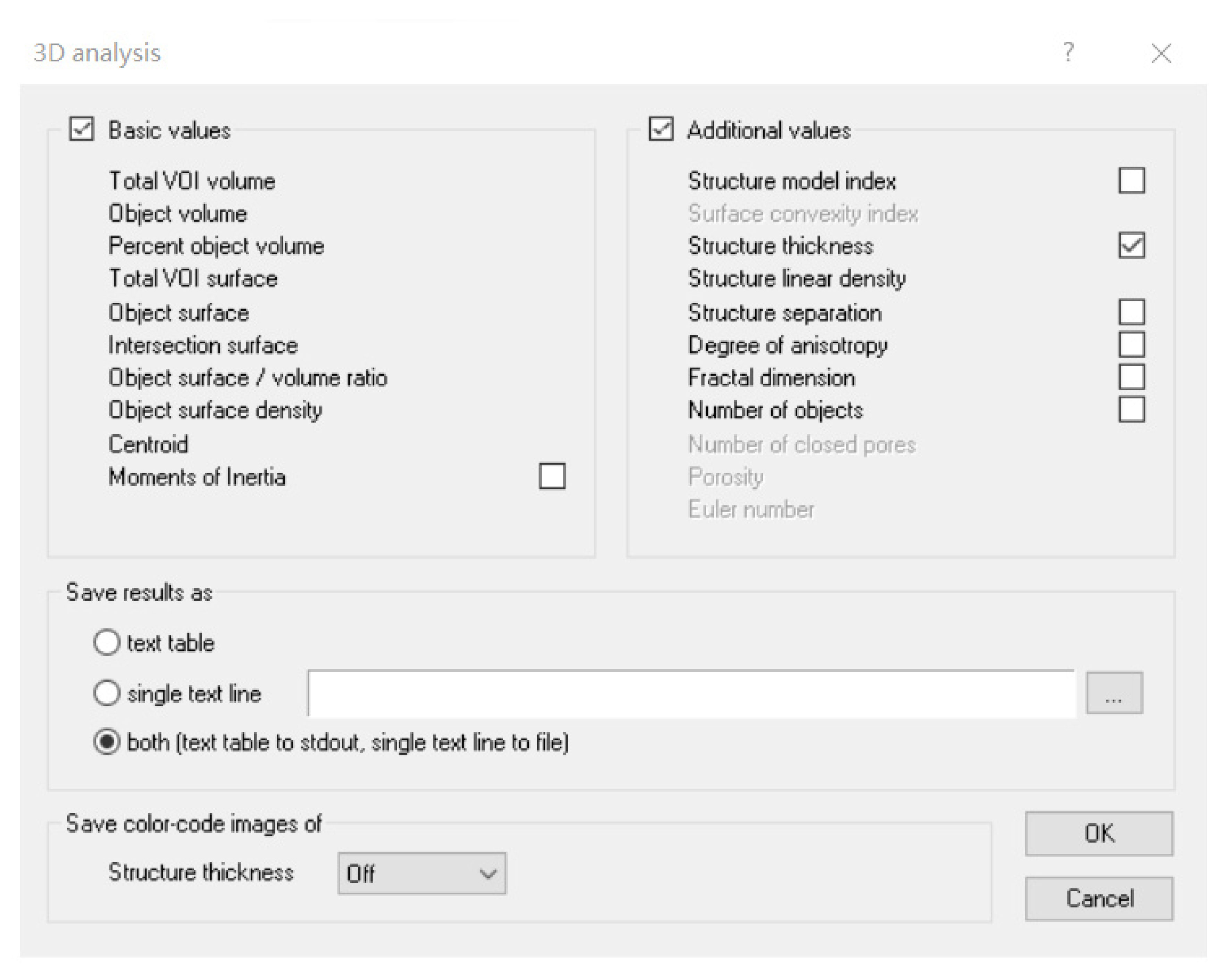
3.4. Quantitative Calculation of Trunk Adipose Tissue

Two indices, body fat content and fat thickness, are often used to assess body fat. Through the use of custom 3D analysis commands in CTAn, the volume of adipose tissue, the ratio of the volume of adipose tissue to the total volume of the tissue, and the thickness of the adipose tissue structure were obtained (Table 4). The total volume represents the volume of the fish trunk. The target volume is the volume of the trunk adipose tissue, accounting for 14.49% of the total volume. The thickness of the trunk adipose tissue structure is 0.3092 mm. Figure 12 is a scatter diagram representing the thickness distribution of adipose tissue, which was calculated by dividing the thickness of adipose tissue into different intervals and drawing the mid-range structural thicknesses according to the volume percentage.

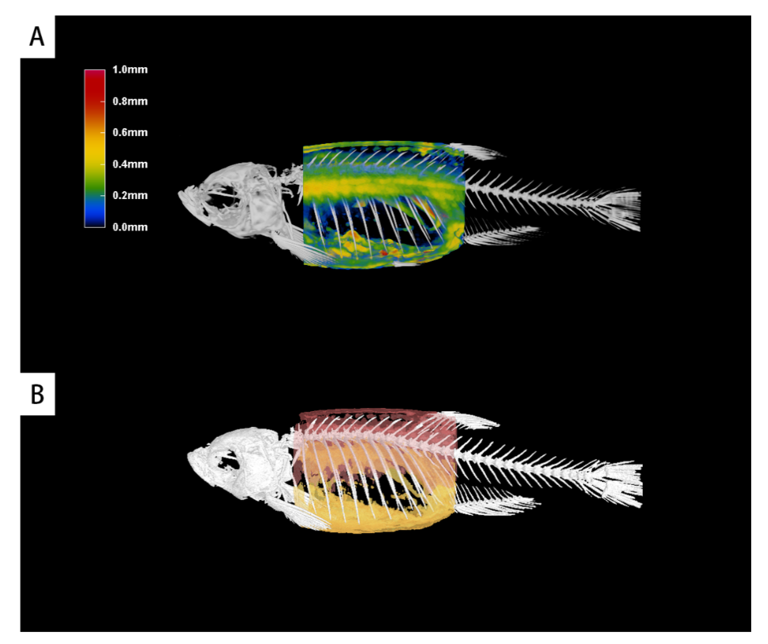
3.5. 3D Graphical Rendering

Figure 13A shows a 3D color rendering diagram based on fat thickness information obtained through the 3D viewing software CTvox, illustrating the spatial distribution of adipose tissue thickness in the fish. The blue part in the figure indicates low fat thickness, and the color change from blue to green, yellow, and red indicates that the fat thickness increased gradually. Figure 13B shows a 3D (surface-rendering) model of adipose tissue volume built using the CTAn software, which could be viewed in the CTvol 3D viewing software. In the figure, red represents subcutaneous fat and back fat on both sides, and yellow represents abdominal fat.

4. Discussion

Micro-CT has become an important tool for rapid and nondestructive high-resolution 3D imaging in biology. Relying on modern X-ray source technology and precision machinery and detection systems, people have constantly pursued higher pixel numbers and ultrahigh spatial resolutions. At present, the resolution of X-ray CT technology has reached 30–50 nm [25,26,27]. Compared with the improvement of the pixels and the resolution, X-ray CT technology has not made much progress in terms of improving the imaging contrast [28]. For weakly absorbing substances such as fat and muscle in biological tissues, the ideal absorbing contrast is often not achieved in high-pixel and high-resolution imaging. The purpose of this experiment was to establish the optimal micro-CT-scanning method of zebrafish adipose tissue. We first compared the scanning effects of zebrafish adipose tissue under 4000 and 2000 pixels. In the experiment, the contrast between zebrafish adipose tissue and non-adipose tissue was the best under 2000 pixels, which was convenient for later image processing and quantitative calculation of adipose tissue. In addition, to improve the absorbing contrast of adipose tissue, low-energy X-rays were used in the scan. Zebrafish bone tissue is much denser than adipose tissue. When using low-energy X-rays for whole-fish scanning, the bone tissue is extremely beam-hardened due to high X-ray absorption, and black artifacts arise around the bone tissue, which seriously affect the subsequent image processing and quantitative calculation of related parameters. This situation is commonly seen in CT scans of metal implants in orthopedics [29]. Scanning the sample at 360° is one effective method to remove scanning artifacts. In this experiment, when scanning at 180° at 2000 pixels, the X-ray was blocked by the bone with high-density, as it could not penetrate the bone, which affected the X-ray imaging and led to the formation of black artifacts. However, in the reconstructed image scanned at 360°, although the X-ray was also blocked by the bone, the missing data from 0 to 180° were supplemented in the scanning from 180 to 360°, which generated more complete data and reduced black artifacts. The boundary between bone tissue and other tissue was clear, which was conducive to image processing and the quantitative calculation of adipose tissue.
From the CT scan of the zebrafish adipose tissue, it was found that there were adipose tissues in the head, abdominal cavity, subcutaneous area, and back of the zebrafish. It is generally believed that the main accumulation sites of fish adipose tissue are the abdominal cavity, liver, and muscle. It is common in fish nutrition research to assess the fat content of fish by detecting the fat content of its abdominal cavity, liver, and muscle [30,31]. We also found fat under the skin of the back and both sides of the body of the zebrafish, indicating that the subcutaneous area is the main accumulation site of zebrafish adipose tissue, and thus, that the accumulation of subcutaneous adipose tissue in fish cannot be ignored.
The accumulation site and content of adipose tissue are closely related to the physiology, biochemistry, and energy metabolism of the animal. Adipose tissue in different sites has different physiological functions in humans and mammals [32,33,34], but the distribution of fish adipose tissue has not yet been clarified. The CT imaging method in this experiment can intuitively reflect the distribution of adipose tissue in the fish, which will be helpful in research on the physiology, biochemistry, and energy metabolism of various fish species. The zebrafish head also has notable adipose tissue, showing that fat is abundant in the brain of the zebrafish, which is not surprising. Animals, including fish, have many phospholipids in the brain. After the animals reach adulthood, the content and composition of brain fat remain basically constant [35].
The content and thickness of adipose tissue can change with age, disease, nutrition, and environmental factors. The quantitative data of adipose tissue are an important indicator of nutritional status evaluation and disease diagnosis in medicine [36,37] and can serve as an early warning about certain diseases [38]. The content and thickness of human abdominal subcutaneous fat are correlated with body mass index, heart mass, and nonalcoholic fatty liver [39,40,41]. In the aquaculture industry, due to improper feeding, fish lipid metabolism often becomes dysregulated, which leads to various diseases and affects the health of the aquaculture industry. At present, in research on fish lipid metabolism, the extraction method is mainly used to detect the fat content of the sample. The extraction method is to dry and weigh the sample, add chemical reagents after grinding to extract the crude fat of the sample, weigh the crude fat, and, from this, calculate the fat content of the sample [42]. The disadvantage of this method is that many steps and considerable time are required, the fish needs to be killed in a way that damages the fish body, and it can only provide the total fat content, not the adipose tissue thickness or the distribution in 3D space. Due to the shortcomings of this detection method, further in-depth research on fish lipid metabolism has been restricted.
Conventional optical or electron microscopy allows the visualization of two-dimensional images of a specimen surface or of thin slices. However, in most cases, a conclusion about original 3D object structures cannot be made on the basis of two-dimensional information. One can obtain the 3D information of object structures by cutting them into very thin slices, which can then be visualized in the light microscope and the two-dimensional information can be interpolated into a 3D structural model. This method, however, is not only very cumbersome but also not very reliable since the object structure itself can be altered by the preparation technique and the distance between the slices is usually too coarse to avoid the loss of 3D information. The X-ray tomography system allows us to visualize and measure complete 3D object structures without sample preparation or chemical fixation. MicroCT has great potential in the study of hormones, signal pathways, tissues, organ (cardiovascular) development, and metabolism. It is expected to become the third widely used laboratory standard imaging instrument after the light microscope and the electron microscope, and to fill the gap between the light microscope and the electron microscope.

5. Conclusions

Our study introduces the principle of adipose tissue imaging using CT technology, optimizes the parameters of zebrafish adipose tissue scanning, explains the steps required to calculate fat parameters using the CTAn data processing software in detail, constructs a 3D dynamic model of zebrafish adipose tissue distribution, shows the different areas where adipose tissue is distributed in the zebrafish body, and provides a new, rapid, nondestructive detection method for fish lipid metabolism research. This technology could become an important tool in the study of fish lipid metabolism.

Author Contributions

Methodology, X.W.; software, X.W.; investigation, X.W. and G.W.; data curation, Y.X. and Y.Z.; Writing—original draft preparation, X.W.; Writing—review and editing, F.Z.; supervision, F.Z.; project administration, F.Z.; funding acquisition, F.Z. All authors have read and agreed to the published version of the manuscript.

Funding

This project was funded by Technical Innovation Project of Instrument and Equipment Function Development of the Chinese Academy of Sciences (2019GZ011) to Fang Zhou.

Institutional Review Board Statement

Not applicable.

Informed Consent Statement

Not applicable.

Data Availability Statement

The datasets used and/or analyzed during the current study are available from the corresponding author on reasonable request.

Acknowledgments

We thank Feng Ge at The Analysis and Testing Center of Institute of Hydrobiology, Chinese Academy of Sciences for experimental and funding support.

Conflicts of Interest

The authors declare no conflict of interest.

References

  1. Niu, H.X.; Qi, F.; Jia, L. Fatty liver disease of fish under intensive culture and its control. Hebei Fish. 2007, 7, 47–48. [Google Scholar]
  2. Cheng, H.L.; Xia, D.Q.; Wu, T.T. Fatty Liver and Regulation of Lipids Metabolism in Fish. Chin. J. Anim. Nutr. 2006, 18, 294–298. [Google Scholar]
  3. Du, Z.Y.; Clouet, P.; Zheng, W.H.; Degrace, P.; Tian, L.X.; Liu, Y.J. Biochemical hepatic alterations and body lipid composition in the herbivorous grass carp (Ctenopharyngodon idella) fed high-fat diets. Br. J. Nutr. 2006, 95, 905–915. [Google Scholar] [CrossRef] [Green Version]
  4. Chatzifotis, S.; Panagiotidou, M.; Panagiotidou, N.; Pavlidis, M.; Nengas, L.; Mylonas, C.C. Effect of dietary lipid levels on growth, feed utilization, body composition and serμm metabolites of meagre (Argyrosomus regius) juveniles. Aquaculture 2010, 307, 65–70. [Google Scholar] [CrossRef]
  5. Yang, H.K.; Huang, K.; Ruan, D.J. Fatty livers of aquaculture fish species and research advances in the control methods. Reserv. Fish. 2007, 27, 4–5. [Google Scholar]
  6. Hölttä-Vuori, M.; Salo, V.; Nyberg, L.; Brackmann, C.; Enejder, A.; Panula, P.; Ikonen, E. Zebrafish: Gaining popularity in lipid research. Biochem. J. 2010, 429, 235–242. [Google Scholar] [CrossRef] [Green Version]
  7. Nordlie, M.A.; Wold, L.E.; Kloner, R.A. Genetic contributors toward increased risk for ischemic heart disease. J. Mol. Cell. Cardiol. 2005, 39, 667–679. [Google Scholar] [CrossRef] [PubMed]
  8. Menendez, J.A. Fine-tuning the lipogenic/lipolytic balance to optimize the metabolic requirements of cancer cell growth: Molecular mechanisms and therapeutic perspectives. Biochim. Biophys. Acta 2010, 1801, 381–391. [Google Scholar] [CrossRef]
  9. Greene, D.; Selivonchick, D.P. Lipid metabolism in fish. Prog. Lipid Res. 1987, 26, 53–85. [Google Scholar] [CrossRef]
  10. Du, Z.Y.; Clouet, P.; Degrace, P.; Zheng, W.; Frøyland, L.; Tian, L.; Liu, Y. Hypolipidaemic effects of fenofibrate and fasting in the herbivorous grass carp (Ctenopharyngodon idella) fed a high-fat diet. Br. J. Nutr. 2008, 100, 1200–1212. [Google Scholar] [CrossRef] [Green Version]
  11. Grunwald, D.J.; Eisen, J.S. Headwaters of the zebrafish-emergence of a new model vertebrate. Nat. Rev. Genet. 2002, 3, 717–724. [Google Scholar] [CrossRef]
  12. Xin, S.C.; Zhao, Y.Q.; Li, S.; Lin, S.; Zhong, H. Application of zebrafish models in drug screening. Genetics 2012, 34, 1144–1152. [Google Scholar]
  13. Chen, F.L.; Zhang, S.L.; Li, Y.C. Advances in toxicology research on zebrafish embryos. Hubei Agr. Sci. 2010, 49, 1484–1487. [Google Scholar]
  14. Wang, M.Y.; Huang, G.D.; Wang, H. Advances in the zebrafish circadian clock mechanisms. Hereditas 2012, 34, 1133–1143. [Google Scholar]
  15. Wu, Y.P.; Xiong, Q.; Zhang, G.X.; Xu, A.L. The Research Progress of Zebrafish Gene Engineering. Acta Genet. Sin. 2004, 31, 1167–1174. [Google Scholar] [PubMed]
  16. Hu, Z.W. Research Advance of Nthinyl Estradiol and Phenanthrene Effect on the Zebrafish (Brachydanio rerio). J. Anhui Agr. Sci. 2014, 42, 12539–12541. [Google Scholar]
  17. Shimada, Y.; Kuninaga, S.; Ariyoshi, M.; Zhang, B.; Shiina, Y.; Takahashi, Y.; Umemoto, N.; Nishimura, Y.; Enari, H.; Tanaka, T. E2F8 promotes hepatic steatosis through FABP3 expression in diet-induced obesity in zebrafish. Nutr. Metab. 2015, 12, 17. [Google Scholar] [CrossRef] [Green Version]
  18. Meguro, S.; Hasumura, T.; Hase, T. Body fat accumulation in zebrafish is induced by a diet rich in fat and reduced by supplementation with green tea extract. PLoS ONE 2015, 10, e0120142. [Google Scholar] [CrossRef] [PubMed]
  19. Dai, W.; Wang, K.; Zheng, W.; Chen, X.; Zhang, W.; Zheng, Y.; Hou, J.; Liu, L. High fat plus high cholesterol diet lead to hepatic steatosis in zebrafish larvae: A novel model for screening anti-hepatic steatosis drugs. Nutr. Metab. 2015, 12, 42. [Google Scholar] [CrossRef] [PubMed] [Green Version]
  20. Yang, Y.H. Application of Hard X-ray Micro- and Nano-CT Techniques in Cell Imaging. Master’ Thesis, University of Science and Technology of China, Hefei, China, 2010. [Google Scholar]
  21. Available online: http://henke.lbl.gov/optical_constants/pert_form.html (accessed on 15 July 2021).
  22. Johns, H.E.; Cunningham, J.R. The Physics of Radiology, 4th ed.; Charles C Thomas: Springfield, IL, USA, 1983; ISBN 0-398-04669-7. [Google Scholar]
  23. Collewet, G.; Bugeon, J.; Idier, J.; Quellec, S.; Quittet, B.; Cambert, M.; Haffray, P. Rapid quantification of muscle fat content and subcutaneous adipose tissue in fish using MRI. Food Chem. 2013, 138, 2008–2015. [Google Scholar] [CrossRef] [PubMed]
  24. Toussaint, C.; Fauconneau, B.; Médale, F.; Collewet, G.; Akoka, S.; Haffray, P.; Davenel, A. Description of the heterogeneity of lipid distribution in the flesh of brown trout (Salmo trutta) by MR imaging. Aquaculture 2005, 243, 255–267. [Google Scholar] [CrossRef]
  25. Yin, G.C. 30 nm resolution x-ray imaging at 8 keV using third order diffraction of a zone plate lens objective in a transmission microscope. Appl. Phys. Lett. 2006, 89, 221122. [Google Scholar] [CrossRef] [Green Version]
  26. Yin, G.C.; Tang, M.T.; Song, Y.F.; Chen, F.R.; Liang, K.S.; Duewer, F.W.; Yun, W.; Ko, C.; Shieh, H.D. Energy-tunable transmission x-ray microscope for differential contrast imaging with near 60 nm resolution tomography. Appl. Phys. Lett. 2006, 88, 241115. [Google Scholar] [CrossRef] [Green Version]
  27. Chu, Y.S.; Yi, J.M.; Cario, F.D.; Shen, Q.; Lee, W.; Wu, H.J.; Wang, C.L.; Wang, J.Y.; Liu, C.J.; Wang, C.H.; et al. Hard-x-ray microscopy with Fresnel zone plates reaches 40 nm Rayleigh resolution. Appl. Phys. Lett. 2008, 92, 103119. [Google Scholar] [CrossRef] [Green Version]
  28. Gui, J.B.; Hu, Z.L.; Zhou, Y.; Zheng, H.R. Technology development of micro-CT with high spatial resolution. Comput. Tomo. Theory Appl. 2009, 18, 106–116. [Google Scholar]
  29. Wang, T.; Xia, W.J.; Zhao, Y.S.; Zhang, Y. Review of metal artifact reduction in computed tomography. Chin. J. Stereol. Image Anal. 2020, 25, 5–21. [Google Scholar]
  30. Cejas, J.R.; Almansa, E.; Jérez, S.; Bolaños, A.; Samper, M.; Lorenzo, A. Lipid and fatty acid composition of muscle and liver from wild and captive mature female broodstocks of white seabream, Diplodus sargus. Comp. Biochem. Physiol. B Biochem. Mol. Biol. 2004, 138, 91–102. [Google Scholar] [CrossRef] [PubMed]
  31. Dong, G.; Zou, Q.; Wang, H.; Huang, F.; Liu, X.; Chen, L.; Yang, C.; Yang, Y. Conjugated linoleic acid differentially modulates growth, tissue lipid deposition, and gene expression involved in the lipid metabolism of grass carp. Aquaculture 2014, 432, 181–191. [Google Scholar] [CrossRef]
  32. Wang, Y.; Rimm, E.B.; Stampfer, M.J.; Willett, W.C.; Hu, F.B. Comparison of abdominal adiposity and overall obesity in predicting risk of type 2 diabetes among men. Am. J. Clin. Nutr. 2005, 81, 555–563. [Google Scholar] [CrossRef] [Green Version]
  33. Du, Z.Y.; Tao, M.; Lock, E.J.; Hao, Q.; Kristiansen, K.; Frøyland, L.; Madsen, L. Depot-dependent effects of adipose tissue explants on co-cultured hepatocytes. PLoS ONE 2011, 6, e20917. [Google Scholar] [CrossRef] [Green Version]
  34. Misra, A.; Garg, A.; Abate, N.; Peshock, R.M.; Stray-Gundersen, J.; Grundy, S.M. Relationship of anterior and posterior subcutaneous abdominal fat to insulin sensitivity in nondiabetic men. Obes. Res. 1997, 5, 93–99. [Google Scholar] [CrossRef]
  35. Horrocks, L.A.; Sun, G.Y.; D’Amato, R. Changes in brain lipids during aging. Neurobiol. Aging 1975, 16, 359–367. [Google Scholar]
  36. Lyu, X.D.; Zhou, Y.M. The role of B-ultrasound measurement of subcutaneous fat thicknesses at different sites in detecting malnutrition. Zhejiang Med. J. 2021, 43, 781–782. [Google Scholar]
  37. Jiao, Y.B.; Deng, L.; Du, P.; Guo, H.; Wang, R.Y.; Fan, X.Y. Study on correlation between body composition and subcutaneous fatty thickness by ultrasonography in adult males. Clin. Med Equip. 2013, 34, 59–60. [Google Scholar]
  38. Wang, Q.A.; Tao, C.; Gupta RKScherer, P.E. Tracking adipogenesis during white adipose tissue development, expansion and regeneration. Nat. Med. 2013, 19, 1338–1344. [Google Scholar] [CrossRef]
  39. Le, J.C.; Wu, Q.P.; Zhou, N.; Zhang, K.; Zheng, D.; Lv, G.L.; Cheng, J.D. Correlation between abdominal wall subcutaneous fat thickness and heart weight in southern Chinese population. J. Forensic Med. 2021, 37, 351–357. [Google Scholar]
  40. Zhao, L. Diagnostic Significance of BMI (abdominal fat thickness) and Common Tumor Markers on Endometrial Cancer. Master’ Thesis, Dalian Medical University, Dalian, China, 2020. [Google Scholar]
  41. Huang, Z.D.; Li, S.C.; Zhang, A.Z.; Wang, X.; Ding, Z.; Zhang, X.F. Correlation between upper abdominal fat volume and body mass index in patients with non-alcoholic fatty liver disease based on magnetic resonance imaging. Chin. J. Magn. Reson. Imaging 2021, 12, 80–83. [Google Scholar]
  42. Folch, J.; Lees, M.; Stanley, G. A simple method for the isolation and purification of total lipides from animal tissues. J. Biol. Chem. 1957, 226, 495–509. [Google Scholar] [CrossRef]
Figure 1. Micro-CT image of a zebrafish abdomen.
Applsci 11 10510 g001
Figure 2. The zebrafish used in the experiment (A) and the sample table used for sample fixation (B).
Applsci 11 10510 g002
Figure 3. Selected and unselected areas in CTAn.
Applsci 11 10510 g003
Figure 4. Upper and lower limits of the threshold range (A) and preview of the selected red area (B).
Applsci 11 10510 g004
Figure 5. CTAn custom processing task list.
Applsci 11 10510 g005
Figure 6. Operation interface in 3D analysis procedure of adipose tissue in CTAn software.
Applsci 11 10510 g006
Figure 7. Scanned images of zebrafish at 180°and 360° with different pixels, (A) an image scanned at 180° at 4000 pixels, (B,C) images scanned at 180° at 2000 pixels in different planes, (D) an image scanned at 360° at 2000 pixels (D).
Applsci 11 10510 g007
Figure 8. Simulated 2D slice observation in the 2D viewing software DataViewer.
Applsci 11 10510 g008
Figure 9. 3D color rendering created using the CTvox 3D viewing software. (A) Sagittal plane; (B) Coronal plane; (C) Axial plane.
Applsci 11 10510 g009
Figure 10. Continuous sagittal CT scan of the adipose tissue of the zebrafish trunk (A) and the area of each slice of adipose tissue (B).
Applsci 11 10510 g010
Figure 11. The position of the standard plane for transverse scanning (A), a continuous cross-sectional CT scan of adipose tissue of the zebrafish trunk (B), and the area of each slice of adipose tissue (C).
Applsci 11 10510 g011
Figure 12. Distribution of trunk adipose tissue thickness.
Applsci 11 10510 g012
Figure 13. Distribution of abdominal adipose tissue thickness (A) and 3D surface rendering (B).
Applsci 11 10510 g013
Table 1. X-ray properties of selected elements under 8-keV X-ray. f1 describes the phase shift, f2 describes the absorption.
ElementAtomic NumberAbsorption Areaf1f2
H15.881 × 10−31.0000.1127 × 10−5
C64.2606.0190.9728 × 10−2
N76.9847.0330.1860 × 10−1
O811.228.0530.3414 × 10−1
Na1128.3111.140.1237
Mg1239.6712.180.1833
P1574.9415.310.4413
S1691.3116.340.5567
K19150.219.421.116
Ca20174.120.381.327
Table 2. Element proportions of biological tissue calculated by mass percentage.
HCNONaMgPSKCaMass-Weighted
Average of Atomic Number
Atomic number1678111215161920
Water11.2--88.8------7.2
Muscle10.212.33.572.90.080.020.20.50.30.0077.1
Fat11.257.31.130.3---0.006--6.1
Skeleton6.427.82.741-0.270.2-14.79.1
Table 3. Optimization of experimental scanning parameters.
Camera Resolution Setting (Pixel Field Width)Image Pixel Size (μm)X-ray Voltage (KV)X-ray Current (μA)Tomographic RotationRotation StepFilter (mm)
Experiment 1200013 55 200 180°0.5°Al 0.25
400010 55 200 180°0.5°Al 0.25
Experiment 2200013 55 200 180°0.5°Al 0.25
200013 55 200 360°0.5°Al 0.25
Table 4. Quantitative calculation of adipose tissue volume.
DescriptionTissue Volume (TV)Object Volume (Obj.V)Percent Object Volume (Obj.V/TV)Structure Thickness Distribution (St.Th)
Unitmm3mm3%mm
385.6255.9114.490.3092
Publisher’s Note: MDPI stays neutral with regard to jurisdictional claims in published maps and institutional affiliations.

