Abstract
The recent increase in ailments has increased the demand for diagnosis and surgery based on X-rays. An X-ray system using a filament-type tube heats the filament for operation, and the electrons emitted by the thermal energy during this process produce X-rays. Conventionally, current control-based methods are used to regulate heating. However, these methods do not control the temperature of the filament, resulting in lower or higher output than the desired dose rate. Therefore, we propose a filament temperature control method that enables constant temperature control, which cannot be achieved using the existing heating method for X-ray systems with filament tubes. Additionally, we developed an indirect temperature estimation algorithm for the tungsten filament to incorporate the proposed method. To validate the tube current control through temperature control, we performed experiments to compare the existing current-controlled heating and temperature control methods in terms of the filament temperature. As the tube current is proportional to the dose rate, it was measured through a comparative analysis of the change in the output of dose rate over time. The obtained results validate that the proposed method can maintain both the filament temperature and tube current at the desired level.
1. Introduction
Images or videos obtained through X-ray equipment are used to diagnose or operate on the affected areas of a patient. As depicted in Figure 1, the image acquisition procedure of the X-ray equipment comprises the following steps [1]:
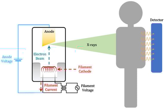
Figure 1.
Schematic of the X-ray image acquisition.
- The filament is heated at a high temperature, and thermal electrons are emitted into a vacuum [2].
- The emitted electrons are accelerated to an anode, generating a tube current that flows through the vacuum tube.
- The accelerated electrons are converted into X-rays after their collision with the anode.
- Certain generated X-rays pass through the patient and reach the detector [3,4].
- An image is obtained after the photons that reach the detector undergo image processing.
Several types of filament heating methods are currently used: analog current control method [5], digital current control method [6,7,8], heating method with a constant gradient to the filament heating current [9], and a method that supplies a constant voltage to the filament. The analog control method configuration has been used in electric step-down transformers and variable resistors. The filament current depends on the resistance and the transformer turn ratio. However, these components increase the system volume and heat generation, and they can heat the filament only at a calculated current value. Due to the miniaturization trend of the industry, the above problems were overcome using the digital current control method. The filament heating current command increases along a constant slope, which is used to reduce the stress on the filament, thereby increasing the longevity of the X-ray tube. Additionally, for faster filament heating, DC is applied to the filament; however, the existing current control method is mainly used due to the filament longevity, cost-efficiency, and volume increase caused by using diodes for the voltage rectifier. In the conventional heating method, the filament is heated to a temperature at which electrical input energy and thermal loss are similar. The thermal energy is proportional to the square of the current flowing. In addition, the resistance of the filament and the thermal property of tungsten change non-linearly with temperature; thus, heat loss and calorific value have a non-linear relationship with temperature. As described above, if there is a difference between the input energy and the lost energy over time, the temperature changes, which in turn changes the amount of X-ray exposure (dose rate) to the patient’s body. This resulted in scenarios where the temperature deviated from the regulated value [10]. Therefore, we aimed to solve the aforementioned problem in this study by controlling the temperature of the filament based on the change in the electrical resistance of tungsten considering its temperature. To validate the effectiveness of the proposed approach in comparison with that of the existing filament heating method, a comparative analysis was performed experimentally based on the changes in the dose rate and filament temperature over time. To compare the dose rate emitted by the X-ray tube, we measured the tube current, which is proportional to the dose rate [11]. Additionally, the filament temperature was observed over an empirical period that is suitable for the experimental conditions to verify that the emitted dose rate can be maintained constant by regulating the filament temperature.
2. Principle of Operation
2.1. Thermionic Emission
Filament temperature can be regulated by understanding the electrical characteristics of the filament as a function of temperature. The filament X-ray tube generates X-rays using thermal electrons emitted into a vacuum from a high-temperature metal that receives energy greater than the work function. The electrons emitted by the heating generate an electron cloud around the filament, and the number of space charges remains constant at a constant filament temperature [12]. Under a constant filament temperature condition, the magnitude of the current density flowing in the vacuum changes owing to the thermal electrons based on the anode voltage. This magnitude can be classified into the space charge-limited regime and temperature-limited regime based on the variation in current density [13]. The equations of Child’s law and Richardson’s law exhibit the correlation between the anode voltage and tube current at a constant filament temperature. Here, denotes the thermal electron acceleration distance; indicates the free space permittivity; represents the electron mass; denotes the electron charge; indicates the anode voltage; represents the Richardson constant of tungsten, which equals 60 ; denotes the work function of tungsten; indicates the Boltzmann constant, which equals 1.3806 ; and represents the absolute temperature .
After determining the anode voltage and tube current values using Equations (1) and (2), the filament temperature is the only variable associated with the tube current. An increase in the temperature of the metal increases the vibrational energy of the metal atoms, which in turn increases the electrical resistance. Table 1 summarizes the electrical resistivity and the change in resistivity rate of tungsten based on the temperature [14,15]. Herein, denotes the resistivity of tungsten, and indicates the ratio of the resistivity at the current temperature to that at room temperature.

Table 1.
Tungsten resistivity and ratio with temperature.
Figure 2 illustrates the resistivity ratio of tungsten considering the temperature listed in Table 1. Based on Figure 2, the electrical resistivity can be expressed as a function of temperature using Equation (3).
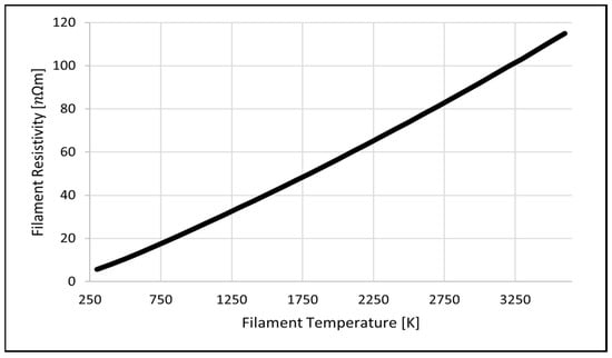
Figure 2.
Temperature dependence of tungsten resistivity.
2.2. Tungsten Thermal Properties
The electrical energy is converted into thermal energy when the tungsten filament applies as the load, as expressed in Equation (4). Here, denotes the load voltage, indicates the load current, and represents the resistance value at absolute temperature . Based on Equation (4), the heating value of the tungsten filament can be obtained, as shown in Equation (5). Here, denotes the mass of the tungsten filament, indicates the heat capacity, and represents the absolute temperature change.
The temperature is maintained constant at the point where the input energy matches the heat loss. However, as the temperature of the metal varies, thermal properties, such as the heat capacity, conductivity, and radiation coefficient, change owing to the variations in the internal energy and vibrational motion of the metal atoms [16,17,18].
The heat losses in the filament of an X-ray vacuum tube are primarily classified into radiation and conduction losses, which can be expressed as indicated in Equations (6) and (7), respectively. Here, represents the conduction heat loss; denotes the thermal conductivity of the material; indicates the heat transit area; represents the absolute temperature change; denotes the conduction distance; indicates the radiation heat loss; represents the Stefan–Boltzmann constant; denotes the emissivity of the material; indicates the surface area of the object; and represents the temperature of the metal.
The relationship between the tungsten temperature, heat capacity, thermal conductivity, and emissivity is presented in Equations (8)–(10) [16].
Figure 3 illustrates the thermal properties of filament considering the temperature based on Equations (8)–(10).
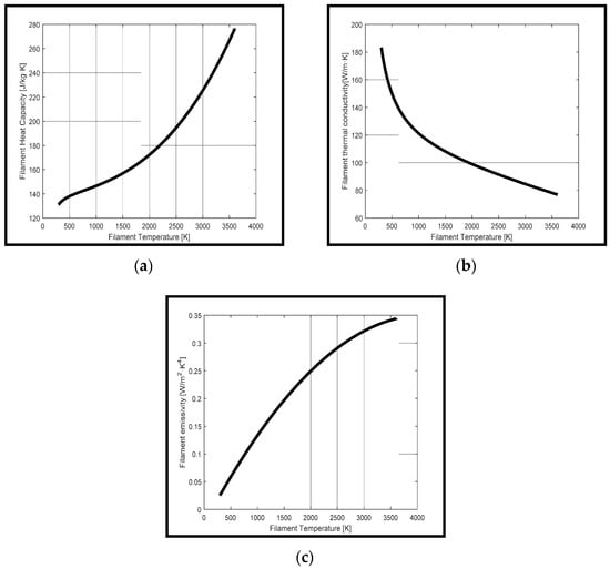
Figure 3.
The thermal properties of filament considering the temperature: (a) filament heat capacity, (b) filament thermal conductivity, and (c) filament emissivity.
Equations (4)–(10) indicate the difference in heat loss based on the temperature of the tungsten filament. When the approximate loss is calculated at 300 and 3000 K, the conduction loss increases from 7.4 mW to 1.579 W, and the radiation loss from 0.1644 mW to 2.0661 W, which varies non-linearly with temperature. Thus, temperature control is essential to maintain it constant considering the non-linear changes of the thermal properties, based on the temperature, of the tungsten filament.
3. Indirect Filament Temperature Estimation Algorithm
3.1. Conventional Method
Filament heating uses a filament driver circuit, as illustrated in Figure 4, to authorize the current command in a step or gradient method to heat the filament [6,7,8,9]. However, as indicated in Equations (4), (5) and (8)–(11), the filament properties based on the temperature and variations in temperature exhibit a non-linear relationship with the input current. Therefore, the current and voltage command values are tuned according to the desired dose rate based on the experience of the medical personnel in terms of the conventional method. Additionally, the sublimation of tungsten reduces its cross-sectional area with the continuous use of the filament tube [9]. This changes the resistance value, causing it to converge to a higher temperature at the same current input. In such cases, it is difficult to control the filament temperature precisely and match the desired tube current.
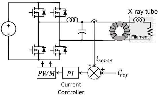
Figure 4.
Conventional filament driver circuit and the control diagram.
3.2. Proposed Method
The filament temperature is uncontrolled in the case of the existing filament heating method, which results in higher dose rates than the required value during the analysis of diseases [9]. Therefore, when operating the X-ray equipment, it is necessary to achieve a certain level of closed-loop temperature control to generate the tube current in the magnitude of the image quality [19] required for the analysis. Therefore, the temperature needs to be measured; however, the heated filament is in the vacuum of the tube and is heated at temperatures higher than 1900 K. Considering the location of the filament and the measurement temperature range, a non-contact temperature measurement method is required. However, as the voltage is high (up to 100 kV) and the vacuum tube is surrounded by insulating oil, introducing the sensors may affect the maintenance and the measurement accuracy owing to the change in emissivity. Hence, it is difficult to configure a closed-loop control considering the directly measured temperature value. To solve this problem, the temperature of the tungsten filament was derived as indicated in Equation (11), considering the change in resistivity based on the tungsten filament temperatures listed in Table 1 [20]. The temperature of the current filament is indirectly estimated in Equation (11) by substituting the electrical resistivity value calculated in the digital signal processor (DSP) [21]. The temperature proportional-integral (PI) controller was constituted using the estimated filament temperature value. As the filament resistance and thermal property variation based on the temperature exhibit a non-linear relationship with the electrical input and heat generation, the PI gain was tuned considering the overshoot and rise time of the current and voltage.
The filament is composed of a tungsten wire in a spiral shape. Although the spiral fabrication generates electrical resistance and inductance components, the inductance at room temperature impedance can be ignored as it accounts for less than 0.001% of the resistance. Therefore, to indirectly estimate the temperature of the tungsten filament using Equation (11), the temperature-based changes in length and cross-sectional area of the filament were disregarded. The error between the estimated temperature and the command temperature is controlled through the PI temperature controller, and the input current required to maintain the temperature is controlled by changing the current command for each error. Therefore, it is converted into a pulse width modulation (PWM) signal through the voltage command of the inverter through the PI current controller to control the filament temperature.
Figure 5 depicts the procedure for achieving an indirect temperature estimation of the filament, which can be summarized as follows:
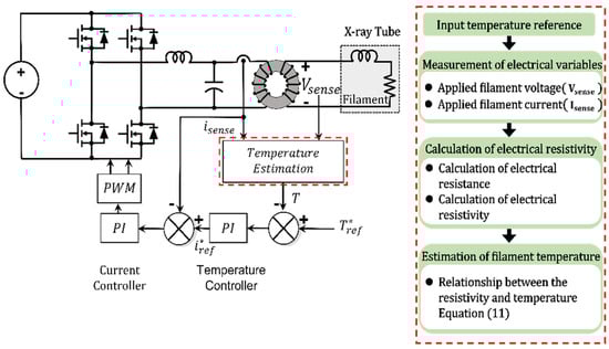
Figure 5.
Filament driver circuit and control algorithm of the proposed method.
- The voltage is measured at both ends of the filament;
- The primary current of the transformer is measured for insulation;
- The measured voltage is divided by the current to calculate the resistance of the tungsten filament. If the heating current is 0 A, the resistance cannot be calculated. Therefore, the calculation must be performed considering the resistance value obtained when the current exceeds a certain value. The heating current at this point represents the maximum heating current value on the filament datasheet, and the flowing current is limited through software;
- The calculated resistance is converted into resistivity based on the length and cross-sectional area of the filament;
- The temperature of the filament is estimated using the resistivity, as indicated in Equation (11).
4. Experiments
To validate the effectiveness of the proposed filament temperature control method, we performed a comparison experiment using the setup depicted in Figure 6. As the proposed temperature estimation algorithm requires highly accurate measurements of the voltage and current authorized to the filament from the filament heating circuit (Figure 5), verification experiments were conducted at the measurement points. Figure 7 and Figure 8 illustrate the waveforms obtained from the verification experiment of the measurement points of the voltage and current authorized to the filament, respectively. Figure 7 depicts the primary and secondary voltages and the root-mean-square (RMS) conversion results of the 1:1 transformer depicted in Figure 4 and Figure 5. Herein, an additional 3.5 V voltage drop was observed between the primary and secondary windings of the transformer, which represents the measurement point of the voltage authorized to the filament. This implies that the primary winding of the insulating transformer is inaccurate. Figure 8 illustrates the results of the current measurements on the primary and secondary windings of a 1:1 insulating transformer. The blue and green waveforms denote the currents on the primary and secondary windings, respectively. As the RMS values of the primary and secondary winding currents coincide at 98%, the results verify that the filament heating current can be measured on both the primary and secondary windings. Therefore, based on the values measured on the secondary winding, we determined that the voltage must be authorized to operate the proposed algorithm. Moreover, the current value measured at the primary winding is used for the operation of the proposed temperature estimation algorithm, similar to the conventional current control method.
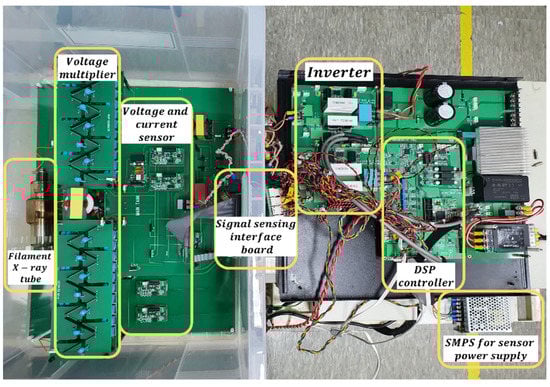
Figure 6.
Experimental setup for comparison of the conventional current control with the proposed temperature control.
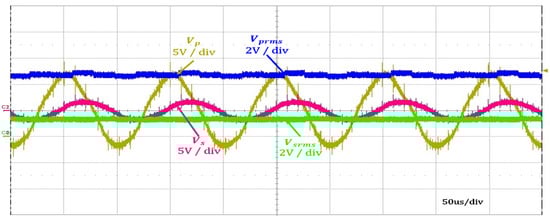
Figure 7.
Primary winding and secondary winding voltage results of the filament in the insulating transformer. (Note: ).
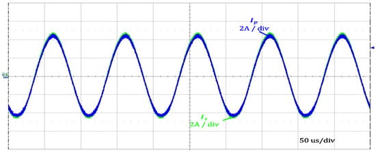
Figure 8.
Primary winding and secondary winding current results of the filament in the insulating transformer. (Note: ).
To estimate the temperature using the measured heating voltage and current values and to verify the accuracy, stability, and repeatability of the controller, experiments were repeated 10 times for a total of 5 reference temperatures from 1700 to 2100 K with a difference of 100 K. Figure 9 shows the results of five waveforms of a reference temperature, estimated temperature and temperature error at each reference. Table 2 shows the results of displaying the maximum and minimum temperature error value, reference temperature, average temperature, and average error to show the accuracy of temperature control for each reference.
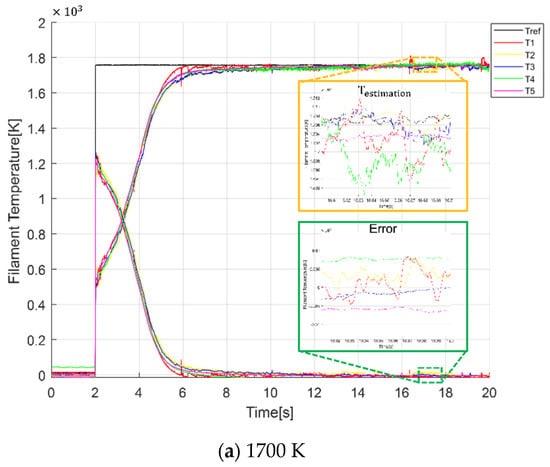
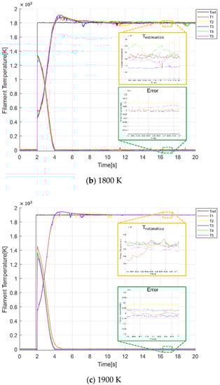
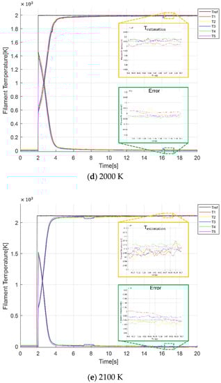
Figure 9.
Reference temperature, estimated temperature, and temperature error waveforms for temperature references of (a) 1700 K, (b) 1800 K, (c) 1900 K, (d) 2000 K and (e) 2100 K.
Table 2.
Comparison of the temperature controller accuracy for different temperature references.
As a result of temperature control, the overall average error was 3.1 K, and the repeatability and stability were verified. Furthermore, we performed an experiment to verify whether the magnitude of the tube current and estimated temperature value in the X-ray tube change over time using the aforementioned heating method. The results were compared with those obtained from the control-based conventional heating method. This experiment used an anode voltage of 15 kV, wherein few X-rays were generated. The verification was based on two estimated temperatures of 1900 and 1950 K, which were obtained using an experimental method for the generation of tube currents of 0.5 and 1 mA at the aforementioned anode voltage. The command currents in the conventional current control method were maintained at 2.57 and 2.67 A, wherein the filament temperature estimation result satisfied the relevant temperature. Figure 10 and Figure 11 illustrate the comparison experimental results of the tube current and estimated temperature waveforms at 1900 and 1950 K, respectively. Temperature heating and convergence were obtained at 5 s and 4 s, respectively, based on empirical values according to the experimental conditions.
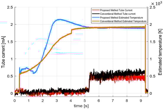
Figure 10.
Comparison of the conventional and proposed methods at 1900 K.
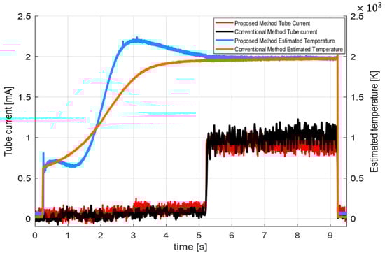
Figure 11.
Comparison of the conventional and proposed methods at 1950 K.
In Figure 10 and Figure 11, the estimated average temperature over time has a ripple of ±10 K in comparison with the reference temperature in both methods. However, the conventional heating method exhibits a maximum temperature increase of 50 K over time. To confirm the dose reduction effect, first, the average tube current value was obtained in the period when the tube current flowed. The effect was verified by measuring the dose rate using Fluke’s 451B-DE-SI-RYR at a distance of 1 m from the X-ray tube. Table 3 summarizes the results of the comparative analysis of the average current and variations in the estimated filament temperature over time based on the results depicted in Figure 10 and Figure 11. When the average current values of the proposed method and existing heating method were compared, we observed an additional tube current of 17% and 9%, respectively. As listed in Table 4, the total dose rate value for 4 s reduced to 89% at 1900 K and 94% at 1950 K. Furthermore, we experimentally verified (Figure 10) that when the filament is heated using the conventional current control method, the filament temperature changes over time, resulting in an additional tube current of up to 0.1 mA in comparison with that generated in the proposed method.
Table 3.
Comparison of the conventional and proposed methods in terms of the average tube current.
Table 4.
Comparison of radiation dose rate.
5. Conclusions
To reduce the variations and maintain a constant level of tube current during the operation of an X-ray system, we propose a temperature control method based on a filament temperature estimation method. Owing to the position and operating temperature of the filament, direct measurement, and control of the heated temperature is difficult. Therefore, we developed an indirect temperature estimation algorithm based on the change in electrical resistance of tungsten. We performed a comparative verification of both the existing and proposed heating methods based on the tube current magnitude and temperature level over time. The results of the indirect temperature estimation algorithm and the experimental results of the tube current were analyzed. The comparative analysis confirmed that a change in the filament heating temperature over time between the conventional and proposed methods differed by up to 50 K. Consequently, an excessive generation of the tube current of up to 0.1 mA was observed in the existing method, in comparison with that observed in the proposed method. In addition, when the actual dose rate was measured through a dose-measuring device, it was confirmed that the amount of dose was reduced by 6% or 11%, depending on the heating method.
The temperature control proposed in this study is based on the indirect temperature estimation method, which is a form of constant control at a human-commanded temperature value over a period. However, additional research on the algorithm is required to generate temperature commands considering user convenience and achieve concurrence with the output dose rate obtained from the filament X-ray tube.
Author Contributions
Conceptualization, H.-L.Z. and J.-J.J.; methodology, H.-L.Z.; software, H.-L.Z. and J.-J.J.; validation, H.-L.Z. and J.-J.J.; formal analysis, J.-J.J.; investigation, H.-L.Z. and J.-J.J.; resources, H.-S.M.; data curation, J.-J.J.; writing—original draft preparation, J.-J.J.; writing—review and editing, H.-S.M.; visualization, J.-J.J.; supervision, H.-S.M.; project administration, H.-S.M.; funding acquisition, H.-S.M. All authors have read and agreed to the published version of the manuscript.
Funding
This research received no external funding.
Institutional Review Board Statement
Not applicable.
Informed Consent Statement
Not applicable.
Data Availability Statement
The datasets used and/or analyzed during the current study are available from the corresponding author on reasonable request.
Acknowledgments
This study was supported by Konkuk University.
Conflicts of Interest
The authors declare no conflict of interest.
References
- Seibert, J.A. X-ray imaging physics for nuclear medicine technologists. Part 1: Basic principles of X-ray production. J. Nucl. Med. Technol. 2004, 32, 139–147. [Google Scholar] [PubMed]
- Behling, R. X-ray tubes development-IOMP history of medical physics. Hist. Med. Phys. 2018, 1, 7–55. [Google Scholar]
- Falavigna, A.; Ramos, M.B.; Wong, C.C.; Barbagallo, G.; Brodk, D.; Al-Mutair, A.; Ghogawala, Z.; Riew, K.D. Commentary: Worldwide knowledge and attitude of spine surgeons regarding radiation exposure. Neurosurgery 2018, 83, E153–E161. [Google Scholar] [CrossRef] [PubMed]
- Mahesh, M. The AAPM/RSNA physics tutorial for residents fluoroscopy: Patient radiation exposure issues 1. Radiographics 2001, 21, 1033–1045. [Google Scholar] [CrossRef] [PubMed]
- Bushberg, J.T.; Seibert, J.A.; Leidholdt, E.M., Jr.; Boone, J.M. The Essential Physics of Medical Imaging, 2nd ed.; Lippincott Williams & Wilkins: Philadelphia, PA, USA, 2001; pp. 97–144. [Google Scholar]
- Kim, Y.J.; Maruyama, Y.; Nakaoka, M. Practical evaluations of resonant pole-assisted ZVS-PWM DC/DC converter with series capacitor-connected transformer parasitic parallel resonant tank. In Proceedings of the Annual IEEE Power Electronics Specialist Conference, Seattle, WA, USA, 20–24 June 1993. [Google Scholar]
- Seo, Y.M.; Byun, M.S.; Hong, S.C. Hybrid type X-ray generator for fluoroscopy X-ray system available in low-capacity AC power source. In Proceedings of the 9th International Conference Power Electronics, Seoul, Korea, 1–5 June 2015. [Google Scholar]
- Villegas, P.J.; Díaz, J.; Pernía, A.M.; Martínez, J.A.; Nuño, F.; Prieto, M.J. Filament power supply for electron beam welding machine. IEEE Trans. Ind. Electron. 2015, 62, 1421–1430. [Google Scholar] [CrossRef]
- Sasic, B.; Pindrys, S.; Willsey, J. Functional Role of X-ray Generators in Industrial Applications; Spellman High Voltage Electronics Corporation: Hauppauge, NY, USA, 2018. [Google Scholar]
- Faraj, K.A.; Ali, R.T.; Saeed, A.O. Quality control and radiation dose rates measurement from diagnostic X-ray examination at different places of hospitals in Sulaimania. Int. J. Recent Res. Appl. Stud. 2013, 16, 62–72. [Google Scholar]
- Bruno, A.C.; Mazaro, S.J.; Amaral, L.L.; Rego, E.M.; Oliveira, H.F.; Pavoni, J.F. Biological X-ray irradiator characterization for use with small animals and cells. Braz. J. Med. Biol. Res. 2017, 50. [Google Scholar] [CrossRef] [PubMed]
- Nottingham, W.B. Thermionic Emission; The Research Laboratory of Electronics Massachusetts Institute of Technology: Cambridge, MA, USA, 1956. [Google Scholar]
- Schonenberger, C.; Oberholzer, S. Shot Noise: From Schottky’s Vacuum Tube to Present-Day Quantum Devices. In Fluctuations and Noise in Materials (Proceedings of SPIE); SPIE: Washington, DC, USA, 2004; p. 5469. [Google Scholar]
- Forsythe, W.E.; Watson, E.M. Resistance and radiation of tungsten as a function of temperature. J. Opt. Soc. Am. 1934, 24, 114–118. [Google Scholar] [CrossRef]
- Zerda, T.W. Stefan Boltzmann Lamp 1008523; 3B Scientific Physics: Hamburg, Germany, 2013. [Google Scholar]
- Shabalin, I.L. Ultra High Temperature Materials; Springer: Heidelberg, Germany, 2014; pp. 237–315. [Google Scholar]
- Cezairliyan, A.; McClure, J.L. High speed (subsecond) measurement of heat capacity, electrical resistivity, and thermal radiation properties of tungsten in the range 2000 to 3600 K. J. Res. Nat. Bur. Stand. 1971, 75, 283–290. [Google Scholar] [CrossRef]
- Tanabe, T.; Eamchotchawalit, C.; Busabok, C.; Taweethavorn, S.; Fujitsuka, M.; Shikama, T. Temperature dependence of thermal conductivity in W and W–Re alloys from 300 to 1000 K. Mater. Lett. 2003, 57, 2950–2953. [Google Scholar] [CrossRef]
- Borgea, S.; Campbell, N.; Gomes, A.; Raszkowski, A.M.; Rook, J.W.; Sanderud, A.; Vallinga, A.; Vouillamoz, A.; Buissink, C. Experimental article—Maintaining image quality for pediatric chest CTs while lowering dose: FBP versus SAFIRE. Reconstruction in CT. In Proceedings of the OPTIMAX 2014: Radiation Dose and Image Quality Optimisation in Medical Imaging, Portugal, Lisbon, 1–31 August 2014; pp. 16–20, ISBN 978-1-907842-60-3. [Google Scholar]
- Chondrakis, N.G.; Topalis, F.V. Evaluation of heat transfer coefficient of tungsten filaments at low pressures and high temperatures. Appl. Therm. Eng. 2010, 31, 258–267. [Google Scholar] [CrossRef][Green Version]
- Mortimer, G.W. Real-time measurement of dynamic filament resistance. J. Illum. Eng. Soc. 1998, 27, 22–28. [Google Scholar] [CrossRef]


Publisher’s Note: MDPI stays neutral with regard to jurisdictional claims in published maps and institutional affiliations. |
© 2021 by the authors. Licensee MDPI, Basel, Switzerland. This article is an open access article distributed under the terms and conditions of the Creative Commons Attribution (CC BY) license (https://creativecommons.org/licenses/by/4.0/).