Review

Design and Fabrication Technology of Metal Mirrors Based on Additive Manufacturing: A Review

1
Changchun Institute of Optics, Fine Mechanics and Physics, Chinese Academy of Sciences, Changchun 130033, China
2
University of Chinese Academy of Sciences, Beijing 100049, China
3
Smart Optics Co., Ltd., Changchun 130102, China
*
Author to whom correspondence should be addressed.
Appl. Sci. 2021, 11(22), 10630; https://doi.org/10.3390/app112210630
Submission received: 23 September 2021 / Revised: 28 October 2021 / Accepted: 9 November 2021 / Published: 11 November 2021

Abstract

:
In recent years, much progress has been made on the development of metal mirrors based on additive manufacturing (AM). The sandwich mirror is well known for its excellent mechanical properties and challenging machining. Now, AM can be used to fabricate this complex structure and reduce the processing time and cost. In addition, with the aid of some new design methods for additive manufacturing, such as lattice, topology optimization (TO), and Voronoi, the freedom of mirror structure design is enormously improved. The common materials of mirrors include ceramics (SiC), glasses (glass ceramics, fused silica), and metals (aluminum, beryllium). Among them, the AM technology of metals is the most mature and widely used. Researchers have recently extensively developed the new-generation metal mirror to improve performance and lightweight rate. This review focuses on the following topics: (1) AM technologies and powder materials for metal mirrors, (2) recent advances in optomechanical design methods for AM metal mirrors, (3) challenges faced by AM metal mirrors in fabricating, and (4) future trends in AM metal mirrors.

1. Introduction

With the rapid growth of space optics and aerospace technology, the applications of reflective optical systems are increasing year by year. A case in point is that off-axis three-mirror-anastigmat (TMA) systems have been widely used due to their unique advantages of large aperture and no central occlusion [1]. Meanwhile, the growing requirements for optical systems’ performance, such as resolution and imaging quality, drive the development of focal length and aperture to larger sizes. In turn, the weight, surface accuracy, manufacturing time, and mirror cost are progressively demanding. In recent years, the lightweight space camera used for remote sensing with high resolution has become a global research hotspot in advanced optics [2]. It should be noted that mirrors are critical elements that directly affect the resolution and other optical systems’ characteristics. Therefore, suitable mirror materials and optimal lightweight structures should be selected carefully according to different requirements and boundary conditions.
The common materials of mirrors include ceramics (SiC), glasses (glass ceramics, fused silica), and metals (aluminum, beryllium). The parameters of several common materials are depicted in Table 1 [3]. The metal mirrors stand out from the crowd with their distinctive advantages: easy to process and manufacture, extremely lightweight, short fabrication time, and low cost [4,5]. Moreover, with ultra-precision machining technology such as single-point diamond turning (SPDT), metal mirrors can be efficiently machined to the optical accuracy range [6,7,8,9,10,11,12]. Currently, beryllium and aluminum are two kinds of materials that are widely used in metal mirrors. The 6.6 m aperture primary mirror of the James Webb Space Telescope (JWST) consists of 18 beryllium sub mirrors [13], and the Widefield Infrared Survey Explorer (WISE) [14,15] adopts an all-aluminum design scheme, with aluminum mirrors mounted to an aluminum structure, as shown in Figure 1. Furthermore, a lot of research has been done to develop metal mirrors with a lighter weight and better structural rigidity to meet the requirements of optical systems.
The variants of lightweight mirror design include arched mirrors, open-back mirrors, and sandwich mirrors (Figure 2) [16,17,18,19]. Daniel Vukobratovich found that the sandwich mirror has the best mirror efficiency in 1989 (Figure 3). The mirror efficiency is defined as the total mirror height divided by the mechanical deflection; a high efficiency is desirable [20]. However, the high-precision welding techniques adopted in the fabricating process of metal sandwich mirrors greatly raises costs and risks. In recent years, AM technologies for metal fabrication have been developed rapidly. It provides an effective way to reduce the difficulty of manufacturing complex structures [16]. AM can offer a complete process chain (Figure 4) for the direct production of these complex lightweight mirrors such as sandwich mirrors [21,22].
As shown in Figure 4, the process chain of AM metal mirrors is different from that of conventional mirrors, mainly in the mirror blank prefabricating stage. After the preparing stage, there are two paths: the design for additive manufacturing (DfAM) and design for conventional machining (DfCM). DfAM is driven by design functionality. It can redesign parts, components, and even systems in AM to achieve the overall requirements with fewer materials and better optomechanical integration. Thus, DfAM has become a new paradigm of advanced design and intelligent manufacturing compared to conventional design. The core technology of DfAM is simulation-driven optimization design technology, including creation-based design technology, topology optimization (TO) design technology, lattice design technology, parameter optimization design technology, and simulation analysis technology [23]. The development of DfAM and AM is changing the pattern of metal mirror designing and manufacturing.
The porosity and residual stress of the forming parts during the AM process should be carefully dealt with to avoid warpage, fracture, and other side effects. Hence, densification and heat treatment must be carried out after prefabricating. The subsequent optical processing and test stage are the same for metal mirrors based on conventional processing including optical processing, surface modification, and polishing. These steps are all critical to obtain the required surface accuracy and roughness.
Table 2 shows the intercorrelations among material utilization, machining time, repair rate, and cost of several processes in fabricating complex structural parts [24]. In brief, AM has revolutionized the way of manufacturing optical and structural components compared to conventional subtractive manufacturing. Furthermore, it is easier to achieve the optimal structure to meet the requirements and optomechanical integration combining DfAM means. Though few AM metal mirrors are put into actual engineering, the prospect is still comprehensive, especially in optical remote sensing, which is of tremendous research significance and value.
This paper aims to review the recent advances of AM metal mirrors and provide a picture of current challenges and future trends. First, the AM technologies applicable for metal mirrors are described, and a comparison of the characteristics among these technologies has been made in Section 2. Some research results on lightweight mirror design based on DfAM are listed in Section 3. Then, Section 4 discusses the current problems for fabricating AM metal mirrors and the corresponding solution measures. Finally, AM metal mirrors’ future development trends and the directions of AM metal mirrors have been given in Section 5, providing reference and thinking for further research.

2. Additive Manufacturing Technology for Metal Mirrors

Additive manufacturing (AM), more commonly known as three-dimensional (3D) printing, is a rapid prototyping technology. It is a craft of manufacturing parts layer-upon-layer based on a digital model file. The specific process creates 3D models using computer-aided design (CAD) software and then slices and designs support through 3D-printing software. Finally, all the information is sent to a 3D printer, which stacks two-dimensional (2D) slices until the product is manufactured (Figure 5) [25].
AM is a manufacturing method of “bottom-up” accumulation compared with the conventional machining mode. This makes it possible to manufacture novel geometries, complex structures, and customized parts limited by conventional processing methods [26]. AM offers some advantages, such as material savings, design freedom, parts almost in their final shape, design freedom, and reduction of time to market. It has been used wildly in aerospace, biomedicine, and automotive parts manufacturing.

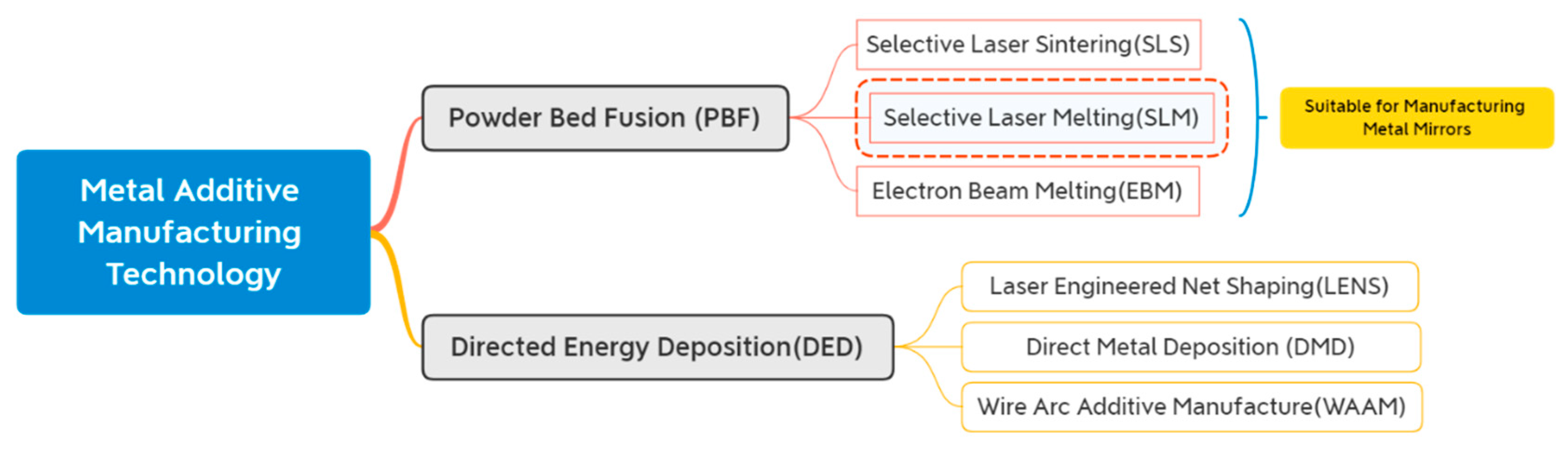
2.1. Metal Additive Manufacturing Technology

Metal AM technologies fall into two categories: (Figure 6) powder-bed fusion (PBF) and directed energy deposition (DED). DED covers 16% of the metal AM market and uses laser beams, electron beams, or electric arcs as energy sources to deposit the melting powder. It uses coaxial or lateral powder feeding methods, which are more practical than PBF’s laying powder. Still, the accuracy of DEDed products is not as high as the PBFed. DED is more suitable for manufacturing large and high-performance integral components. PBF is ideal for small, ultra-complex monolithic components such as metal mirrors, owing to its products’ good surface finish and high density [27,28].
Figure 7 shows the schematic of SLS. The first step is to coat a layer of powder on the platform, then preheat the powder to near the melting point to reduce the residual stress. After that, the laser beams illuminate specific areas on the cross-section according to the data of the corresponding sliced model’s layer. Using the same technique, repeat the process of laying powder and sintering until a part forms. The principles of other PBF techniques are similar to this, repeating the coating and scanning processes. Table 3 presents an overview of the materials and AM technologies for fabricating metal mirrors in recent years. It can be seen that all the mirrors are fabricated using PBF, namely EBM, SLS/DMLS, and SLM. The most common choice is printing AlSi10Mg via SLM. This section describes several PBF technologies and compares the pros and cons of each process for AM.

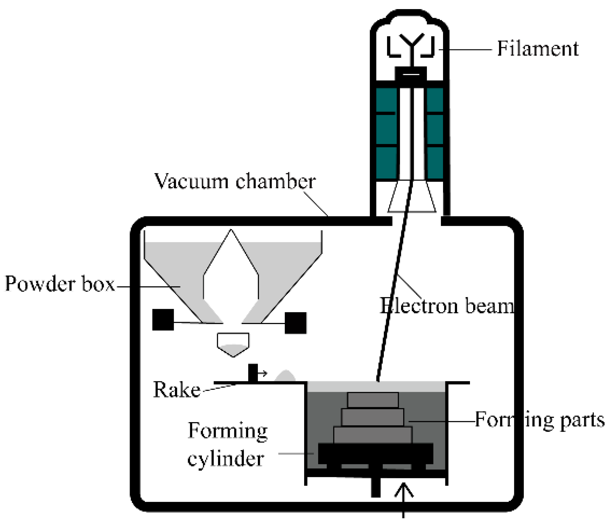
2.1.1. Electron Beam Melting (EBM)

EBM was invented in 1993 in Sweden at the University of Technology in Gothenburg. Arcam was founded in 1997 and sold its first commercial system in 2002. The most significant difference between EBM and the other two PBF technologies is that the heat source replaces laser beams with electron beams. The EBM system consists of an electron beam gun, vacuum chamber, forming a cylinder, and powder distribution mechanisms (Figure 8). In a vacuum environment, high-energy fast electron beams are controlled to melt the powder selectively and build up a forming part [38].
The power of electron beams is about 3–6 kW, which is an order of magnitude higher than laser beams. At the same time, the EBM has the advantage of high energy utilization. EBM is suitable for printing high melting temperature powders such as Ti alloy. Moreover, EBM is not influenced by the optical reflectivity of the powder. However, the disadvantages of EBM are also evident. Intense X-rays can be produced during EBM, and therefore adequate protection measures must be taken. Besides, EBM has limited dimensions for building parts, with a maximum diameter of 350 mm and a height of 380 mm. Due to the unique energy conversion mechanism of the electron beam, serious liquid metal splash which results in porosity occurs in the process of printing aluminum alloy via EBM. Furthermore, the precision of printing is low. There are few reports on fabricating Al alloys by EBM to date because of its process characteristics [39]. In the research on metal mirrors, only the University of Arizona used EBM to print a Ti alloy mirror. Its surface was poor, so EBM is not an appropriate technology for mirrors.

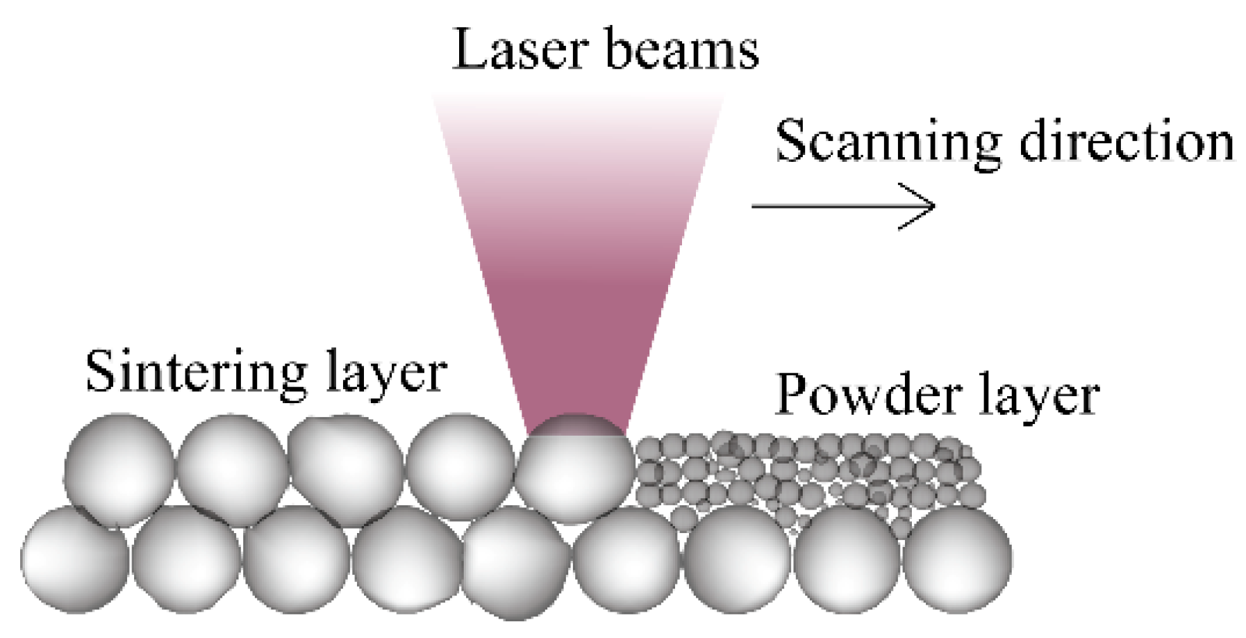
2.1.2. Selective Laser Sintering (SLS)

SLS was developed by C.R. Dechard at the University of Texas in 1989. Sintering uses a laser beam as the heat source to melt part of the powder with a low melting point so that transient wetting liquid promotes metallurgical bonding or inter-particulate melting across the layers of sintered components (Figure 9). The powder with high melting point bonds together after the liquid metal solidifies and then forms a rough component, achieving the liquid-phase sintering effect [40]. Due to only partial melting, the surface quality and density of the forming parts are poor. Hence, SLS cannot meet the requirements for high-precision metal mirrors.

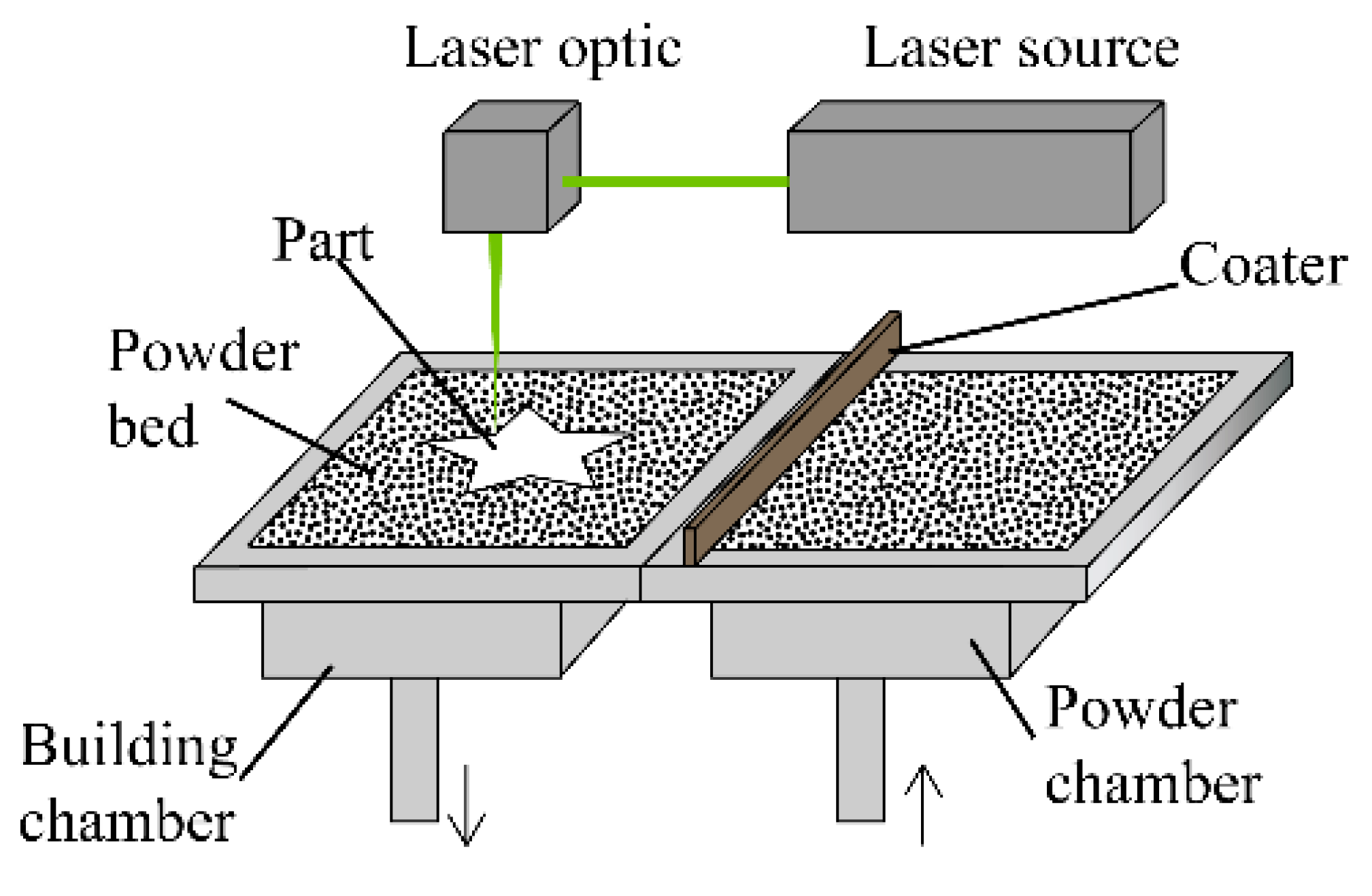
2.1.3. Selective Laser Melting (SLM)

SLM based on SLS was proposed by the Institute of Fraunhofer in Germany in 1995 and successfully developed in 2002. It integrates the advantages of SLS, which melts powders layer-by-layer and forms under the protection of inert gas to prevent the reaction between powder and other gas. The main difference between the two is that SLM can achieve full melting, as shown in Figure 10, in a single component, single material powder, and was initially applied only to pure metals [41]. In contrast, SLS processes cannot heat the powders above the melting temperature and form parts with somewhat less than ideal density. Meanwhile, its equipment price and process complexity are above SLS.
SLM is a technology that has been commonly used to manufacture metal mirrors in recent years, as shown in Table 3. In theory, forming parts via SLM have higher density and mechanical properties than via laser sintering. SLM’s products have high dimensional accuracy, a smooth surface, and high density [42]. The laser power of SLM solutions’ 3D printer can reach 700 W easily, which is high enough to pre-print mirror blanks. SLMed parts’ density is up to 99.0% and above. The above technical advantages have gradually promoted SLM to the mainstream technology for fabricating AM metal mirrors.

2.2. Additive Manufacturing Metal Mirror Fabricating Considerations

2.2.1. Material Type

With the continuous development of AM technologies, printing materials have become increasingly abundant. At present, there are more than 300 kinds of materials for AM, mainly polymers, metals, ceramics, and biomaterials [43]. Metal materials that are frequently used are aluminum alloys, titanium alloys, nickel-based superalloys, stainless steel, and iron alloys. However, the representative materials are still Al alloy and Ti alloy for metal mirrors, which dominate 3D-printed metal mirrors. In 2015, Herzog fabricated AlSi10Mg and Ti6Al4V mirror blanks using SLM and EBM [30], respectively. Nevertheless, after optical post-processing, the mirror surface of the final Ti mirror was far from the requirements. The details of this are further described in Section 3. Therefore, aluminum alloy is the material which more widely used to fabricate AM metal mirrors.
At present, the aluminum alloys used in manufacturing mirrors are mainly Al-Si alloy and Al-Mg-Si alloy, including AlSi7Mg0.6, AlSi10Mg, AlSi12, and AlSi40. The addition of silicon improves the fluidity of aluminum and reduces its melting temperature. Adding magnesium to aluminum can not only improve its strength but also improve its strain-hardening ability. AlSi10Mg is the Al alloy which most intensively investigated, and the technology of printing AlSi10Mg by PBF is very mature. Table 4 provides the multiple parameters of PBFed AlSi10Mg and as-cast AlSi10Mg after the high pressure of die-cast (HPDC). The ultimate tensile strength and ductility values in additively manufactured AlSi10Mg are generally higher than or equal to as-cast and HPDC AlSi10Mg, which can be attributed to the fine microstructures seen in AM samples [28]. Therefore, the AlSi10Mg mirrors have excellent microstructure and mechanical properties. However, in engineering, the designers should consider the system requirements, prefabricating techniques, and post-treatment to make the best material choice.
Noteworthily, the mismatch of CTE between AlSi10Mg and NiP is a problem for the use of AlSi10Mg for mirrors. The bimetallic bending effect is serious in the service environment with large temperature changes. The Institute of Fraunhofer (IOF) tested the AM mirror of AlSi40, which can better improve temperature adaptability.

2.2.2. Design of Support

Support design is indispensable (Figure 11). Due to the sandwich mirror’s overhanging structures having no casting and molding support constraint, edge warping and collapse easily occur during the forming process. Even severe deformation interruption can happen [44]. Although some printing techniques have powder or liquid support constraints, they are not strong enough. Moreover, support can also reduce the residual stress of forming parts, and a high-quality support design is vital for the surface roughness and accuracy of parts. However, support design is one of the craft difficulties in AM metal mirrors depending on various factors such as forming processes, printing materials, and parts’ characteristics [45].
The support structures can be added through 3D printing software automatically and removed after AM prefabrication using wire cutting and labor-intensive manual removal. However, some support structures are too complex. The optimization of the support is essential. We can optimize support with the help of TO, which reduces materials waste and the difficulty of removal [47]. The tilt angle prevents the need for added support in sandwich mirrors’ interior and mirror distortion during printing. Some unique structures can be designed to form self-support at a specific angle range to minimize the trouble of removing them later [48,49]. The materials of the support should be consistent with mirrors to ensure the mirrors’ accuracy. In addition, the numerical simulation should be used to achieve the intelligent design of the support, and its forming effect should be predicted by heat transfer and force analysis.

2.2.3. Connectivity Constraints

The connectivity constraint requires no enclosed voids inside mirrors. For PBF, there should be no residual powder inside parts. Compared to open-back mirrors and arch mirrors, sandwich mirrors are closed-back, so connectivity constraints must be considered in the design stage. In the mirror design, the structure walls are perforated to present complete airflow channels inside the mirror, meeting the connectivity of the airflow and facilitating the removal of residual powder (Figure 12) [50,51,52]. Finally, ultrasonic cleaning and other methods are used to remove the powder from the interior of the parts altogether.

3. Design Technology of Additively Manufactured Metal Mirrors

Mirrors’ weight is an important factor when highly dynamic scanning applications are desired or for space optical system applications. Thus, a light weight is a key parameter to the optomechanical design of metal mirrors. How to match the relationship between weight and structural stiffness is the technical difficulty of mirror structural design. As Section 1 mentioned, lightweight structures of mirrors include the arched mirror, open-back mirror, and sandwich mirror. It is necessary to consider various factors, such as fabricating difficulty, cost, and processing time. The introduction of AM provides mirrors’ structural design more freedom. DfAM methods can offer a good compromise between mechanical functionality and material usage. And a well-thought DfAM strategy is a major factor in the economy and the success of an AM part. In this section, AM metal mirrors with different internal lightweight structures are given, including conventional structure, TO structure, lattice structure, and Voronoi structure. All the structures are explained and compared in detail according to the corresponding research results. It is worth noting that these internal structures can be combined in practical applications, such as TO and lattice and TO and Voronoi.

3.1. Conventional Design

The so-called conventional design is a lightweight design that can be manufactured by conventional machining and modeled by standard CAD software programs. Figure 13 and Table 5 show quintessential lightweight holes for mirrors and the performance comparison of each hole, respectively. Generally, quadrilateral holes and regular triangle holes are preferred. However, the triangle holes are the best choice, given their highest stiffness with the same weight [53,54].
Corning’s researchers designed and fabricated a four-inch circular flat mirror with a honeycombed lightweight structure in 2016. They prefabricated the mirror blank by printing AlSi7Mg0.3 powder via DMLS. After SPDT and polishing, the surface roughness could reach RMS 1.5 nm (see Figure 14). Therefore, Woodard’s team proposed and preliminarily demonstrated the feasibility of manufacturing metal mirrors utilizing AM by comparing them with various other materials and methods. They thought the layer-by-layer SLS process and the resulting long cycle times, which are a function of the volume of material rather than complexity, are what drive the costs [17]. Finally, they concluded that the AM metal mirror has advantages in fabricating complex structures, reducing cost [29].
The round and square mirrors shown in Figure 15 were manufactured by Optimax Systems in 2017 [32]. The material used was FeNi36, whose CTE is near zero. Furthermore, it is suitable for the application of metal mirrors in cryogenic and space applications. However, the finished mirrors were not entirely dense when measuring them with a scanning white-light interferometer. The test result shows that the finished optical surface exhibited a 9 μm void. The mirrors were in the experimental stage and had not been put into practice. Further surface modification and polishing are needed for applications at wavelengths shorter than the infrared.
In 2018, E. Hilpert’s team from IOF in Germany designed and compared the performance of five lightweight metal mirrors: solid mirror, drill mirror, open-back mirror with honeycomb, sandwich mirror with honeycomb, and empty mirror (Figure 16) [33]. For the sandwich mirror, the stiff and strong face sheets carry the bending loads, while the core resists shear loads. The results of the modal analysis show that the sandwich mirror with honeycomb has the best mechanical properties (Figure 17). It has the second lightest weight, only after the open-back structure, which precisely verifies the sandwich mirror’s advantages in many aspects given in Section 1. Moreover, this experiment has laid a theoretical and practical foundation for the team’s next-generation AM metal mirrors.
By summarizing the experience, Songnian Tan et al. from Changchun Institute of Optics, Fine Mechanics and Physics (CIOMP) fabricated an Al mirror based on SLM technology in 2020 [37]. The mirror is a flat metal mirror with the dimensions of 67 mm × 50 mm used as a fast-steering mirror (FSM) in the infrared optical system. They adopted a relatively conventional design method, as shown in Figure 18. The final lightweight rate reached 43.7% while meeting the internal connectivity constraints. After AM prefabrication, λ / 10   ( λ = 632.8   nm )   of the surface shape was achieved through CNC machining and optical processing, which meets the application requirements of the infrared level.

3.2. Topology Optimization (TO)

TO is one of the structural optimization methods. It is derived from topology and used to calculate the optimal material spatial distribution for given problems. In general, the topologically optimized part can theoretically meet the load demand and achieve the optimal material distribution under a specific algorithm, which can obtain the optimal load-bearing structure under a particular volume fraction [55]. In generative design, multiple solutions are calculated simultaneously to create the most optimal solutions based upon functional and non-engineering requirements, such as manufacturability [56,57]. The results produced by TO are often very complex and challenging to manufacture directly. So, the combination of TO and AM technologies has the potential to bring significant synergy benefits. Now, AM metal mirrors based on TO are analyzed as follows.
First, Herzog et al. from the University of Arizona, USA, proposed a process chain for manufacturing metal mirrors based on AM and hot isostatic pressing in 2015 [30]. They utilized DMLS and EBM technologies to print AlSi10Mg and Ti6Al4V, respectively. After that, the products’ quality and method feasibility obtained by the two routes were compared. The mirror model is a cylinder with a bottom diameter of 4 in and a height of 38.1 mm. And the mirror structure was topologically optimized by applying a binding force to the mirror surface to achieve a light weight (Figure 19). After further grinding and polishing, the aluminum mirror was found to have a surface roughness of 22 nm and a surface accuracy of PV 255 nm. However, the Ti mirror did not reach expectations because of the subsurface porosity in the mirror (Figure 20).
Subsequently, Carolyn Atkins’ team used DMLS to print an astronomical X-ray mirror. Then the TO of the arches lightweight design was carried out, and the final lightweight rate reached 62% through iterative calculation. The mirror’s diameter was 40 mm, with a 4mm thickness in total and a 1mm thickness of the front and back surfaces which formed the sandwich structure. While satisfying the lightweight requirement, its support was a continuous ring structure to reduce the print-through effect and improve its structural stiffness (Figure 21). Finally, the optimized mirror’s mass was reduced from 9.2 g to 6.4 g, but the surface roughness increased from 2.47 nm to 5.22 nm [18,35,36].

3.3. Lattice

The word “lattice” derives from the old French “latte” which is defined as a structure consisting of strips of wood or metal crossed and fastened together with square- or diamond-shaped spaces left between [58]. However, in DfAM, it is a type of cellular material with truss-like frames optimized for specific loading conditions. Lattice structures are obtained by arraying abundant lattice cells. They perform similarly to atoms inside a crystal in space. Multiple extensive research studies have been performed to determine the mechanical behavior of lattices and to find the optimal structure. In [59,60,61], the properties, performance, applications, and challenges of SLM lattice structures were well reviewed. The current ultra-lightweight metal lattice structures can achieve a lightweight of 85% or more as well as high specific stiffness, specific strength, and high energy absorption [62]. Their applications in 3D printing have been relatively widespread, such as in medicine, acoustics, and electronics, but there are few examples of their usage in mirror manufacturing.
There are about20 sorts of lattice cells, and Figure 22 gives several quintessential structures. They are repeated over a part of the volume of the component to be manufactured. Furthermore, numerous lattice structures can be obtained by arranging lattice cells with different sizes, densities, and types. Proper lattice cells can be decided via the finite element analysis (FEA) method. Figure 23b below shows a lightweight hammer handle made by adding lattice cells of different densities [63]. Hence, the structures obtained by arranging the same lattice periodically are known as the uniform lattice. Conversely, the non-uniform lattice structures consist of the lattice cells inclined to randomization. Furthermore, TO can be introduced to achieve a macro–micro integrated structure with lattice. PTC Creo, Siemens NX, Autodesk Netfabb, and Materialise Magics are commercial 3D-printing software that generate lattice structures conveniently.

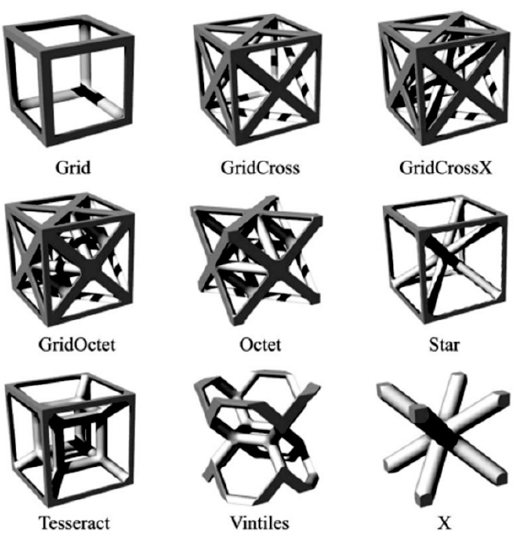
3.3.1. Uniform Lattice

As mentioned above, the uniform lattice periodically arranges lattice cells with the same type and density into a uniform lattice structure. Carolyn Atkins’ team at the UK Centre for Astronomical Technology applied the lattice to the internal structure of a metal mirror for the first time, with the support of the CCAM CubeSat project. The product is a concave spherical mirror with a radius curvature of 350 mm. Its mechanical diameter and thickness are 84 mm and 17.3 mm, respectively. Researchers used Autodesk Netfabb software to design and optimize the lattice structure of the mirror. Then they tested and summarized the structure of numerous lattice cells. The final choice is BCCz lattice, whose performance and weight are optimal, and the resulting mirror’s lightweight rate reached 31% (Figure 24) [64].
The team performed a set of comparative experiments with six technical routes, as shown in Figure 25. The results in Table 6 show that, except for the directly polishing AlSi10Mg mirror blank (Route 5), all other mirrors reached the visible or infrared levels. The reason for that may be that the polishing process touched a fractured layer through the analysis of X-ray tomography and microscope magnification. The pores are large, so the sample’s surface roughness did not meet the requirements. This experiment demonstrated the feasibility and practicality of the lattice structures in metal mirrors and laid the foundation for future iterative experiments [65,66].

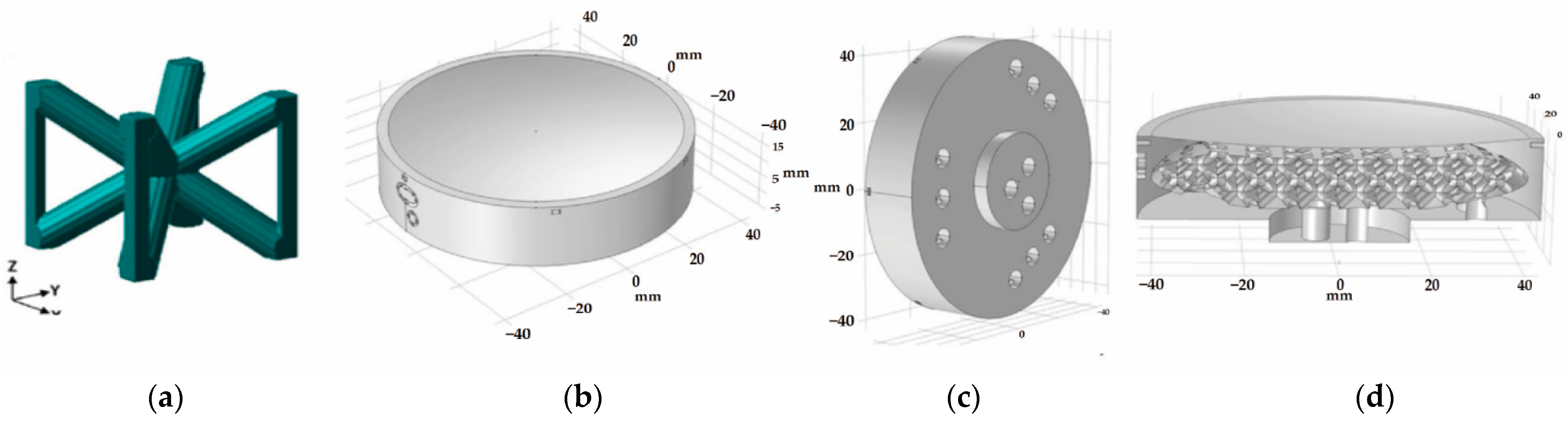
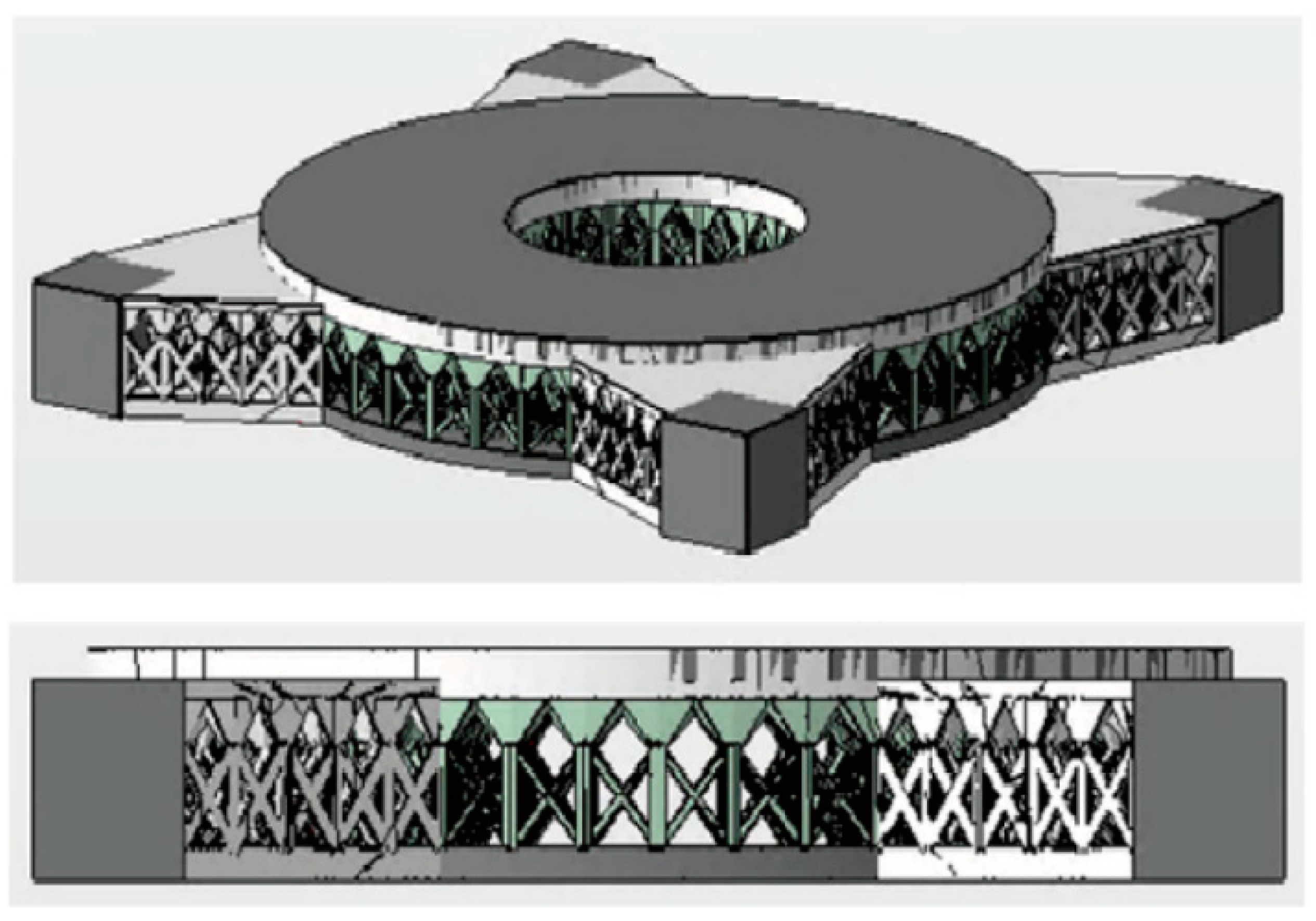
3.3.2. Non-Uniform Lattice
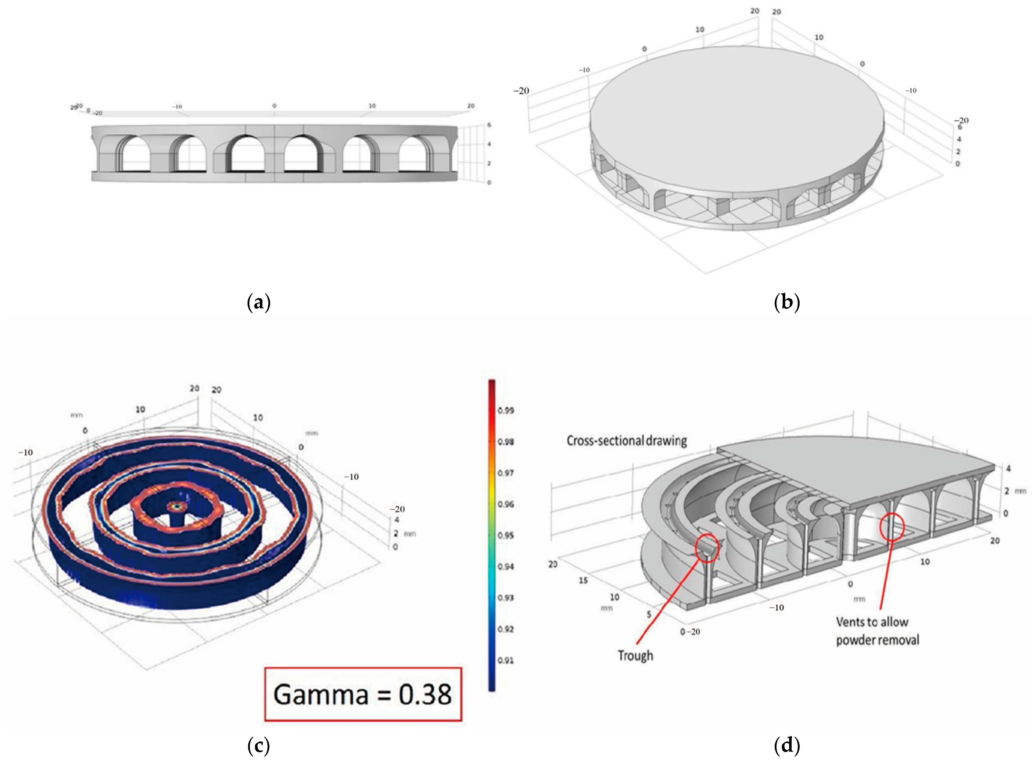
The non-uniform lattice, in contrast to the uniform lattice, tends to be arranged randomly. It is denser at locations where greater stiffness is required. Moreover, combining it with TO can achieve greater design freedom compared with the uniform lattice. The model in Figure 26 is the iterative product of Carolyn Atkins’ team in Section 3.3.1, and the lightweight rate is up to 50%. However, this is not the final product of the project. The team is carrying out the third and fourth iterations to seek the relatively optimal structure and explore a technical route for fabricating metal mirrors with lattice structures [65,66,67].

3.4. Voronoi

Voronoi, named after George Voronoi, refers to contiguous polygons composed of vertical bisectors for segments connecting two adjacent points. The distance from any point in a Voronoi polygon to a point controlled by the polygon is less than that of others [68]. It was first applied to calculate the average rainfall based on the discretely distributed weather stations. After that, people found that a lot of examples of Voronoi exist in nature, such as in cell structure and leaf micro-texture (Figure 27). Due to its particular structure and good mechanical properties, Voronoi has been widely used in the architecture and biomedical fields. For metal mirrors, it is challenging to realize this complex structure with conventional processing. Hence, the combination of AM and Voronoi is a perfect choice.

3.4.1. 3D Voronoi

Voronoi can be divided into 2D and 3D manufacturing types according to the spatial distribution, whereas 3D Voronoi looks more like foams. Mici from Lockheed Martin proposed using 3D random foams to further optimize the TO mirror (Section 3.2) [31]. The ultra-lightweight mirror is designed with a macro–micro combination of TO and 3D Voronoi (Figure 28). Then, it was fabricated with the same material and printing method. The randomness of the seeds that generate Voronoi may cause unnecessary overlaps among them. So, they used Lloyd’s algorithm to drive the distribution of the random foams to homogeneity. Finally, the feasibility of this method was verified by FEA and mechanical property testing.

3.4.2. 2D Voronoi

The team of Hilpert from IOF finally chose a sandwich mirror with the honeycomb structure after an experimental comparison of the five structures introduced in Section 3.1. By summarizing the previous designing and manufacturing experience, they optimized the mirrors’ internal structure. The honeycomb structure was replaced with the 2D Voronoi cell pattern to make the design of the mirror’s support more effective. AlSi40 was chosen as the substrate material, which CTE matches electroless nickel as plating. Thus, it was conducive to minimizing the influence of the bimetallic bending effect on the stability of mirrors [69,70,71,72,73,74].
The internal structure was obtained as follows. Firstly, the Poisson disk sampling method is used to distribute seeds, avoiding undesired clustering. However, the uniform Voronoi cannot satisfy the whole mechanical requirements of the mirror body, so the Voronoi should be further optimized through FEA and modal analysis. In order to make the interface of mounting structures stiffer, the 2D Voronoi was denser in the three areas (Figure 29). The wall thickness was set at 0.5 mm, and then the 2D Voronoi was pulled up to mirrors’ 3D support by SLM. Finally, the lightweight rate of the secondary mirror was 60.5%, with a surface accuracy of RMS 7.3 nm and surface roughness of 1.1 nm [39].
Then they machined the primary mirror and the third mirror on one substrate, drastically reducing the processing time and the number of alignment degrees of freedom to be fixed during the integration phase. The bounding box of the whole element was 205 mm × 339.5 mm × 60 mm. The mirrors had a surface accuracy of RMS 20 nm and surface roughness of RMS 1 nm, so all mirrors were at the visible level [75,76].

3.5. Summarization

This section reviewed the internal structures for AM metal mirrors. The unique fabrication capabilities of AM processes have offered more design freedoms for engineers. Specific design methods are needed to meet these opportunities and challenges. However, conventional designs cannot surpass the advantages of AM. Research on DfAM has gradually increased in recent years. It can be seen that TO plays a crucial role among DfAM methods. The idea and application of TO can be found in numerous DfAM methods, such as generative design, optimization for Voronoi, and optimization for non-uniform lattice. Hence, designers should master TO algorithms and the application of the related software. Furthermore, the FEA simulation is a necessary means to verify the design. In addition, the thermodynamic analysis for space mirrors is essential because of the special working environment.
After reviewing the summary of the mirrors’ structural designs, it is clear that the stochastic lattice has better mechanical properties. Moreover, the multiscale design is the future development trend of DfAM, such as micro lattice infilling after macro TO. While realizing the ultra-lightweight condition, it meets the requirements of structural mechanics.
It is worth noting that many structures are inspired by nature. Lattice mimics the microstructure of crystals, and Voronoi is enlightened by bionic ideas such as cells. Is it possible to draw on nature to find other, more suitable structures for metal mirrors in future scientific research? For example, the unique royal water lily can bear an adult without sinking into the water. Likewise, there are a thousand strange snowflake microstructures (Figure 30). Further exploration should be carried out [77,78,79].

4. Challenges Faced in the Development of AM Metal Mirror

Figure 3 shows the process chain of AM metal mirrors, and the steps can be summarized into five parts: the preparing stage, designing stage, mirror blank prefabricating stage, optical processing stage, and testing stage. The mirror blank prefabricating stage and designing stage have been described in detail in Section 2 and Section 3. Post-processing includes the following steps: (1) densification is a necessary step in the AM process, which helps to reduce the porosity of parts and enhance the mechanical properties; (2) heat treatment helps to reduce the residual stress generated during the printing and improve the dimensional stability; (3) optical processing includes the SPDT, surface modification, and polishing, which is the final step to obtain mirrors with good surface roughness and surface accuracy. According to engineering experience, post-treatment accounts for a large part of the overall cost and time. Due to the broad scope of post-processing techniques available to mirror fabrication, this section addresses only several key issues encountered in post-processing and gives the corresponding solutions.

4.1. Porosity

Porosity is one of the most important criteria for evaluating AM products. Fusion errors, gas pores, and shrinkage pores are three types of pores in AM parts. PBF can be seen as a micro-welding, which causes sizeable residual stress inside the part during the unique process of rapid melting and solidification. Improper selection of laser power, scanning speed, or other parameters can result in cracking, holes, low density, and poor forming quality [80]. Other pores are attributed to an insufficient supply of liquid metal during the solidification process. As shown in Figure 31, the mirror’s holes are obvious under the light, which affect surface accuracy. Therefore, selecting the best processing parameters and carrying out densification for the forming parts are essential. Surface modification is required if necessary. Moreover, the standard methods used to test porosity are scanning electron microscopy (SEM) and computed tomography (CT).

4.1.1. Powder Quality

The quality of the powder directly affects the finished products. The main parameters of powder are particle size, sphericity, fluidity, and density. PBF requires infinitesimal powder, a narrow size range, and a sphericity of 98% or more to manufacture high density and performance parts [27]. The more refined powder, the smaller the pores between particles, so the denser powder layer. The fine powder melts more with the same heat source than coarse powder because of the more prominent surface area.
Consequently, it lends to the greater sintering drive, which is conducive to obtaining excellent metal parts. Generally, the suitable particle size range for SLM powder is 15–53 μm. If the range distribution is vast, the surface of powder laying will be delaminated. That will also result in the uneven melting of metal powder and a severe increase in the porosity or surface roughness of formed parts [23]. Powder with the normal distribution of particle size range has the best effect. Owning to the high energy conversion rate and the high energy density of electron beams, the suitable particle size range for EBM powder is 53–150 μm. Other parameters are similar to those of the SLM.
The manufacturing of high-quality powder remains a critical challenge due to its high surface area and susceptibility to oxidation. In the process of SLM, the gas elements may form holes and other local defects, resulting in the reduction in densification and mechanical properties of parts. Therefore, the content of oxygen, nitrogen, and other elements shall be strictly controlled. Generally, the mass fraction of oxygen in metal is less than 0.15 wt%, and the mass fraction of nitrogen in metal is less than 0.05 wt% [81]. An assessment of the manufacturing routes of powders and their respective performances during the AM processes is important. The most commonly used is conventional gas atomization (GA), which has the advantages of high capacity, good efficiency, and a low cost [82,83]. The powder cannot satisfactorily print the high-quality and high precision parts due to deficiencies of varying powder size and high oxygen content. Other ways of mainly making alloy powders are plasma rotating electrode process (PREP) and plasma atomization (PA) [84].
Figure 32 shows the SEM images of Ti-6Al-4V powder generated by different methods. PREPed powders are perfectly spherical in shape with smooth surfaces. However, high-quality powders are expensive because of the high cost of the fabrication process, such as PREP, and the low yield of the atomization process. In the PBF process, the solid powders can be reused to reduce cost, although such reuse of powder particles results in an irregular shape and poor surface finish of the final part [85]. Therefore, powders used as feedstock materials must be selected by considering both their quality and cost in association with the corresponding AM process. So, the powder with better sphericity and more uniformity is obtained, which meets the requirements of preparing metal mirrors.

4.1.2. Hot Isostatic Pressing (HIP)

HIP is an effective method used for densifying metal parts which began in the 1950s. It is mainly used to prepare powder superalloy and improve casting properties as well as metallic structures. The principle is to place a part in a closed chamber and heat. At the same time, inert gas is used as the working medium to exert the same pressure on the part from all directions, which densifies it under high temperature and pressure (Figure 33) [86]. Hence, this process is termed isostatic pressure. The high pressure and temperature can eliminate the most pores and cracking in the parts. Because the part is extruded from all directions, HIP has relatively little effect on the part’s dimensions. Moreover, it positively impacts residual stress relief, anisotropy reduction, and fatigue behavior improvement [87,88].
HIP is necessary post-processing for AM mirror blanks. Figure 34 presents a comparison of Songnian Tan’s product before and after HIP. The porosity of the mirror blanks reduced from 0.092% to 0.005% [37]. The result of the study showed that in the following HIP treatment, the internal pores were reduced, and the tensile strength was reduced due to the microstructure changes. It further illustrated the feasibility of HIP in post-processing.

4.2. Dimensional Stability

Dimensional instability refers to the change in the dimensional accuracy of mirrors during the designing, manufacturing, using, and storing stages. It is the main factor that determines whether AM mirrors can be used in engineering. Therefore, the smaller the change, the more likely it is that mirrors can meet the requirements of the technical conditions. The dimensional stability that metal mirrors need to reach is the 10−6 level, so the size changes relative to the meter level should be controlled at the micron level [89,90].
Dimensional changes can be divided into four types: (1) First, when the part is placed in a stable environment, the dimension of the mirror changes with time. This process is prolonged and irreversible. (2) The second type is the dimensional change caused by thermal or force cycles, which refers to when the mirror returns from a changing environment to a stable environment. This situation is also a permanent deformation. (3,4) The third and fourth types are dimensional deformations caused by temperature and hysteresis, respectively. There are subtle differences between the two. Both describe the deformation of a part that is moved from a stable environment to another stable environment. The temperature-induced deformation is independent of the change path and a reversible deformation; the hysteresis-induced deformation is related to the change path, resulting in deformation that may be reversible or permanent [89,90,91,92].
Then, these types of dimensional change can be summarized into four factors through a detailed analysis: externally applied stress, non-uniformity, anisotropy of material properties, microstructural variations, and internal stress variations. In practical engineering, the dimensional stability of metal mirrors can be improved, starting from these factors.

4.2.1. Material Characteristics

The material characteristics have a vital influence on the dimensional stability of mirrors. The characteristic parameters include the characteristic thermal parameters: CTE, specific heat, thermal conductivity, and thermal diffusion coefficient; force characteristics include the parameters: stiffness, Young’s modulus, specific stiffness, micro yield strength, and Poisson’s ratio. Among them, the micro yield strength and CTE are essential factors for dimensional stability. The materials can be selected from those introduced in Section 2.2.1 to ensure dimensional stability. Moreover, the same material of optical and mechanical structure can realize the optimal athermalization of optical systems.

4.2.2. Process Parameters

PBF technologies use an energy source to scan the specific areas to melt the powder. There are over 20 process input parameters that need to be set automatically or manually, and possibly more that are not adequately identified, such as scanning speed, scanning path, layer thickness, and laser power. These parameters directly affect the printing speed and the parts’ quality [93]. Olakanmi et al. studied the densification mechanism and microstructure evolution law of SLMed Al alloy parts and considered whether the process parameters play a decisive role in the porosity and pore direction [94]. However, the influence of process parameters on formed parts is not a single effect. Only when different process parameters cooperate can high-performance parts be obtained. For example, when the laser power is relatively weak and the layer thickness is too large, the alloy powder cannot be completely melted. Therefore, before fabricating high-precision AM parts, stimulation for the whole printing process must be performed to find the best scanning strategy and other parameters [95].
The first step is to preheat the forming platform and chamber before printing. Then reduce the areas of uneven thickness and avoid significant cross-section changes. The choice of laser power is also crucial. Generally, the central temperature of the laser beams can reach 3500 K, and its choice is related to the melting point of printing powder. The density increases accompany the laser power as the powder absorbs more energy to facilitate total melting. However, the energy densities begin to cause balling at some point, thereby reducing the density and surface roughness. In addition, different laser scanning strategies can be used to minimize the accumulation of residual stress (Figure 35) [96].
Laser energy density can reflect the influence of scanning speed and laser power on laser energy input. The laser energy density increase can fully melt the power to reduce the pores of the parts. If the laser power density is too high, defects will occur, such as thermal cracks and liquid metal splashes, which can easily happen. A simplified energy density equation has been used by numerous investigators as a simple method for correlating input process parameters to the density and strength of the forming parts. In their simplified model, energy density E A can be found using Equation (1) [25].
E A = P υ × H S
where P is laser power, υ is scan speed, and HS is the scan spacing/hatch spacing between parallel scan lines. In this model, energy density increases with increasing laser power and decreases with increasing scanning spacing and velocity. Due to the high thermal conductivity of Al alloy materials, their laser energy is easily consumed during SLM. Therefore, the molten pool temperature and the fluidity decrease results in defects such as pores and cracks. Table 3 gives some of the performance data of AlSi10Mg printed with different parameters. Obtaining the appropriate liquid viscosity by adjusting the laser energy density reasonably can possibly restrain the spheroidization effect and the generation of microcracks [97].

4.3. Heat Treatment

As mentioned above, residual stress is a critical factor affecting dimensional stability. Like welding, there is much residual stress in metal AM parts. In the process of PBF, each new layer of a part is formed by moving the laser beams through the powder layer, melting the top layer of powder and fusing to the layer below at the same time. The heat flows from the pool to the solid metal below, so the temperature gradient of the melting zone is considerable. It is constrained below the solid structure when a new layer is cooled and solidified on the previous layer [98]. Therefore, shear force is generated between layers because of shrinking. Then, holes, delamination, thermal deformation, and cracking may appear, which deteriorates the dimensional accuracy and mechanical properties of end-use parts. To sum up, residual stress is one of the main challenges in the high-quality manufacturing of metal AM products.
Heat treatment is the most essential and practical measure for reducing residual stress. The main principle is to evenly heat a part and let it soak through the whole part, both the thick sections and thin sections, until it reaches a temperature equilibrium [23,99,100]. The heat treatment for SLMed aluminum alloy parts mainly includes annealing and aging. The main purpose of annealing is to reduce residual stress, eliminate defects, and improve ductility. Aging is a strengthening heat treatment, and its main purpose is to further improve the strength of the alloy. Aging can be also divided into artificial aging and natural aging. At present, T6 heat treatment is the most commonly used. The heat treatment temperature and time of different compositions and content of alloy elements vary greatly. If the heating temperature is too high or the holding time is too long, abnormal grain growth and burning easily to occur, which reduces the mechanical properties. Shielding gas needs to be added in order to relieve stress, even in the vacuum furnace in some exceptional cases. Moreover, the excellent design of parts is also the crux of eliminating residual stress, which minimizes the residual stress and maximum dimensional stability.
The mechanical properties of AlSi10Mg after heat treatment can be found in Table 3. Table 3 shows that after T6 heat treatment, yield strength and ultimate tensile strength increase remarkably. However, for other heat treatment experiments, yield strength and ultimate tensile strength decrease. This can be attributed to the Si phase undergoing thermally activated growth during heat treatment at a high temperature. Therefore, the appropriate parameters should be selected before carrying out the heat treatment. In addition, the precipitated Si phase is spherical, which can reduce the local shear and restrain crack initiation and propagation when deformed. In addition, an increase in the Si particle size and a decrease in the number of Si particles reduce the local stress and strain during tensile loading [101]. Generally, proper heat treatment plays a positive role in the later processing procedure for printing mirror blanks.

4.4. Quilting

The quilting (print-through effect) stems from the influence of mechanical properties during SPDT and polishing [102]. Afterward, the support structures appear on the mirror surface under the FEA, thus deteriorating the surface accuracy (Figure 36). Quilting can reduce the maximum energy at the center of the diffraction disk for the diffraction-limited systems. In the design stage of mirrors, especially for sandwich mirrors, both the cell wall thickness and support structure are the factors that make the quilting of mirrors. Therefore, it must be reduced as much as possible. Daniel Vukobratovich summed up a formula for calculating the quilting amplitude [20]. It can be expressed by Equation (2):
δ c = ψ [ Et f 3 12 ( 1 v 2 ) ] 1 PB 4 ,
where δ c denotes the quilting amplitude (peak to peak), ψ the geometric quilting constant, E Young’s modulus,   t f the front face sheet,   ν the Poisson’s ratio, P the polishing pressure, and B the diameter of the cell-inscribed circle.
It can be seen that the quilting should be reduced in the design stage of mirrors. Firstly, it is important to choose the appropriate material because Young’s modulus and Poisson’s ratio affect the quilting.   ψ is the geometric quilting constant which is different for every lightweight hole (Figure 13), such as ψ square = 0.00126 , ψ triangle = 0.00151 , ψ hexagonal = 0.00111 . In addition, the polishing pressure and the thickness of the front skin are all factors. Figure 37 gives an illustration of the surface distortions created during the polishing process of a lightweight structure. Therefore, it is important to reserve an appropriate machining allowance and control the post-treatment process well to minimize quilting.
DfAM provides more thoughts for mirror design. For example, TO or random foams can provide more uniform and denser support for the mirror surface, which minimizes the low-frequency surface error caused by the processing (Figure 38). The quilting of optimized and unoptimized mirrors from Carolyn Atkins’ team was compared in Section 3.2. The results show that the optimized mirror’s quilting was significantly reduced. Therefore, it is verified that DfAM is effective in reducing the quilting of metal mirrors. In the future, the internal structures of the sandwich mirror could be designed via drawing on the bionic structures to achieve the desired results.

5. Conclusions and Future Trends

The present review shows significant progress has been made in designing and manufacturing AM metal mirrors and lists the problems encountered in the process and solutions. The designing and manufacturing criteria for the metal mirrors are light weight and high stiffness. Furthermore, the sandwich mirror is the primary design in this field because of its well-known stability and light weight. However, compared with the conventional processing method, the difficulty and time of manufacturing sandwich mirrors can be significantly reduced by AM. In addition, there are several internal structure design methods based on DfAM, such as lattice, TO, and Voronoi, which greatly increase the freedom of mirrors design.
SLM has become the most mature and effective metal 3D-printing technology for fabricating metal mirrors now. In the future, material limitations, excessive residual stress in parts, continuous improvement of requirements, a light weight, and change of machining processes are all main factors driving the development and selection of next-generation products. Therefore, further work on AM metal mirror should focus on the following three topics:
(1) Explore and develop other materials suitable for AM metal mirrors, such as beryllium and beryllium-aluminum alloy, and adopt current metal AM techniques to a broader range of materials. Previously, General Dynamics prefabricated a beryllium-aluminum alloy mirror, but the result was not as expected [21]. We should focus on matching processing technologies and powder materials, such as printing beryllium-aluminum alloy powder with high melting points and high-power electron beams. Moreover, AM technologies can also fabricate other materials’ optical components, such as ceramic mirrors, polymer lenses, and liquid lenses [103,104,105]. Utilize them in the application of optical instruments and precision engineering as soon as possible;
(2) High-entropy alloys, magnetic alloys, bulk metallic glasses (BMG), functionally graded materials (FGM), and nano-architected metals are all materials for which advanced research is developing now [106]. Amorphous metals have high elasticity and fracture resistance advantages and are lightweight and beneficial for obtaining high-quality AM products. Moreover, amorphous metal 3D printing technologies, which are ideal for fabricating metal mirrors, can help decrease the internal stress and porosity of the AM products as well as optimize the system’s dimensional stability and environmental adaptability. Figure 39 shows a 3D-printed gear of amorphous metal. However, it is a challenging technology that is limited by multiple factors, such as material crystallization due to the high temperatures, residual stress relieving, and laborious post-processing. Therefore, related research is in the exploration stage [107];
(3) The idea of the integration of macro and micro has been advanced to realize a lightweight design. In Section 3.4, researchers from Lockheed Martin have created a metal mirror which is ultra-lightweight and stiff by combining TO with 3D Voronoi. Furthermore, we should give full play to the idea of multiscale optimization in the design of AM metal mirrors, for example, combing the lattice with TO or Voronoi (Figure 40). In the future, this idea will provide strong technical support for AM metal mirrors, as well as the development of related disciplines and industries.
Though, few AM metal mirrors are put into practical engineering applications. With the continuous development of the AM parts’ densification and surface treatment processes, metal mirrors’ mechanical property and dimensional stability will greatly improve. In a few years, AM metal mirrors can be used at the visible level and even the laser level, so they have broad application prospects.

Author Contributions

Conceptualization, K.Z.; methodology, J.Z.; software, C.W.; formal analysis, H.Q.; investigation, X.X.; resources, L.Y.; writing—original draft preparation, K.Z.; writing—review and editing, H.Q.; visualization, J.Z.; supervision, X.Z.; project administration, H.G. All authors have read and agreed to the published version of the manuscript.

Funding

This research received no external funding.

Institutional Review Board Statement

Not applicable.

Informed Consent Statement

Not applicable.

Data Availability Statement

Not applicable.

Conflicts of Interest

The authors declare no conflict of interest.

References

  1. Yang, T.; Zhu, J.; Hou, W.; Jin, G. Design method of freeform off-axis reflective imaging systems with a direct construction process. Opt. Express 2014, 22, 9193–9205. [Google Scholar] [CrossRef]
  2. Zhang, W.W.; Allgood, K.D.; Biskach, M.P.; Chan, K.-W.; Hlinka, M.; Kearney, J.D.; Mazzarella, J.R.; McClelland, R.S.; Numata, A.; Riveros, R.E. High-resolution, lightweight, and low-cost x-ray optics for the Lynx observatory. J. Astron. Telesc. Instrum. Syst. 2019, 5, 021012. [Google Scholar] [CrossRef] [Green Version]
  3. Zhang, J. Design and Manufacture of an Off-axis Aluminum Mirror for Visible-light Imaging. Curr. Opt. Photonics 2017, 1, 364–371. [Google Scholar] [CrossRef]
  4. Steinkopf, R.; Gebhardt, A.; Scheiding, S.; Rohde, M.; Stenzel, O.; Gliech, S.; Giggel, V.; Loscher, H.; Ullrich, G.; Rucks, P.; et al. Metal mirrors with excellent figure and roughness. In Optical Fabrication, Testing, and Metrology III; International Society for Optics and Photonics: Bellingham, WA, USA, 2008; Volume 7102, p. 71020C. [Google Scholar] [CrossRef]
  5. Matson, L.E.; Chen, M.Y. Enabling materials and processes for large aerospace mirrors. In Proceedings of the Advanced Optical and Mechanical Technologies in Telescopes and Instrumentation, Marseille, France, 23–28 June 2008; p. 70180L. [Google Scholar]
  6. Vukobratovich, D.; Hatheway, A.E.; Schaefer, J.P. Large stable aluminum optics for aerospace applications. In Proceedings of the Optomechanics 2011: Innovations and Solutions, San Diego, CA, USA, 22–25 August 2011. [Google Scholar]
  7. Moeggenborg, K.; Vincer, T.; Lesiak, S.; Salij, R. Super-polished aluminum mirrors through the application of chemical mechanical polishing techniques. In Current Developments in Lens Design and Optical Engineering VII; International Society for Optics and Photonics: Bellingham, WA, USA, 2006; Volume 6288, p. 62880L. [Google Scholar] [CrossRef]
  8. Moeggenborg, K.J.; Barros, C.; Lesiak, S.; Naguib, N.; Reggie, S. Low-scatter bare aluminum optics via chemical mechanical polishing. In Proceedings of the SPIE-The International Society for Optical Engineering, San Jose, CA, USA, 20–23 January 2008; Volume 7060, pp. 706002–706008. [Google Scholar]
  9. Atad-Ettedgui, E.; ter Horst, R.; Lemke, D.; Tromp, N.; de Haan, M.; Navarro, R.; Venema, L.; Pragt, J. Directly polished lightweight aluminum mirror. In Proceedings of the Advanced Optical and Mechanical Technologies in Telescopes and Instrumentation, Marseille, France, 23–28 June 2008. [Google Scholar]
  10. Andresen, B.F.; Carrigan, K.G.; Fulop, G.F.; Norton, P.R. Visible quality aluminum and nickel superpolish polishing technology enabling new missions. In Proceedings of the Infrared Technology and Applications XXXVII, Orlando, FL, USA, 25–29 April 2011. [Google Scholar]
  11. Xie, Y.; Mao, X.; Li, J.; Wang, F.; Wang, P.; Gao, R.; Li, X.; Ren, S.; Xu, Z.; Dong, R.; et al. Optical design and fabrication of an all-aluminum unobscured two-mirror freeform imaging telescope. Appl. Opt. 2020, 59, 833–840. [Google Scholar] [CrossRef]
  12. Andresen, B.F.; Patel, A.M.; Carrigan, K.G.; Fulop, G.F.; Norton, P.R. Update on Tinsley visible quality (VQ) aluminum optics. In Proceedings of the Infrared Technology and Applications XXXVIII, Baltimore, MD, USA, 23–27 April 2012; pp. 83532C–83537C. [Google Scholar]
  13. Clampin, M. The James Webb Space Telescope (JWST). Adv. Space Res. 2008, 41, 1983–1991. [Google Scholar] [CrossRef]
  14. Schwalm, M.; Akerstrom, A.; Barry, M.; Guregian, J.; Ugolini, V. Cryogenic telescope, scanner, and imaging optics for the Wide-field Infrared Survey Explorer (WISE). In Proceedings of the Space Telescopes and Instrumentation 2008: Optical, Infrared, and Millimeter, Marseille, France, 23–28 June 2008. [Google Scholar]
  15. Sampath, D.; Akerstrom, A.; Barry, M.; Guregian, J.; Schwalm, M.; Ugolini, V. The WISE telescope and scanner: Design choices and hardware results. In Proceedings of the SPIE—The International Society for Optical Engineering 2010, San Diego, CA, USA, 7 September 2010; Volume 7796. [Google Scholar]
  16. Ahmad, A. Handbook of Optomechanical Engineering; CRC Press: Boca Raton, FL, USA, 2017. [Google Scholar]
  17. Woodard, K.S.; Myrick, B.H. Progress on high-performance rapid prototype aluminum mirrors. In Proceedings of the Society of Photo-optical Instrumentation Engineers, Anaheim, CA, USA, 11 May 2017. [Google Scholar]
  18. Atkins, C.; Feldman, C.; Brooks, D.; Watson, S.; Cochrane, W.; Roulet, M.; Hugot, E.; Beardsley, M.; Harris, M.; Spindloe, C.; et al. Topological design of lightweight additively manufactured mirrors for space. In Proceedings of the Advances in Optical and Mechanical Technologies for Telescopes and Instrumentation III, Austin, TX, USA, 10–15 June 2018. [Google Scholar]
  19. Atkins, C.; van de Vorst, B. OPTICON A2IM Cookbook: An introduction to additive manufacture for astronomy (Final). Zenodo 2021, 3, 18. [Google Scholar] [CrossRef]
  20. Valente, T.M.; Vukobratovich, D. A Comparison of the merits of open-back, symmetric sandwich, and contoured back mirrors as light-weighted optics. In Proceedings of the Precision Engineering and Optomechanics, San Diego, CA, USA, 10–11 August 1989; pp. 20–36. [Google Scholar]
  21. Sweeney, M.; Acreman, M.; Vettese, T.; Myatt, R.; Thompson, M. Application and testing of additive manufacturing for mirrors and precision structures. In Material Technologies and Applications to Optics, Structures, Components, and Sub-Systems II; International Society for Optics and Photonics: Bellingham, WA, USA, 2015; Volume 9574, p. 957406. [Google Scholar] [CrossRef]
  22. Wang, Y.; Wu, X.; Xu, L.; Ding, J.; Ma, Z.; Xie, Y. Fabrication of a lightweight Al alloy mirror through 3D printing and replication methods. Appl. Opt. 2018, 57, 8096–8101. [Google Scholar] [CrossRef] [PubMed]
  23. Diegel, O.; Nordin, A.; Motte, D. A Practical Guide to Design for Additive Manufacturing; Springer: Berlin/Heidelberg, Germany, 2019. [Google Scholar]
  24. Han, X.; Cao, J.; Lyu, H.; Wang, C.; Ge, J.; Yu, Y. Applications and Development of Additive Manufacturing for Space Optical Remote Sensors. Spacecr. Recovery Remote Sens. 2021, 42, 74–83. [Google Scholar]
  25. Gibson, I.; Rosen, D.W.; Stucker, B.; Khorasani, M. Additive Manufacturing Technologies; Springer: Berlin/Heidelberg, Germany, 2021; Volume 17. [Google Scholar]
  26. Kumar, S. Additive Manufacturing Processes; Springer: Berlin/Heidelberg, Germany, 2020. [Google Scholar]
  27. Frazier, W.E. Metal Additive Manufacturing: A Review. J. Mater. Eng. Perform. 2014, 23, 1917–1928. [Google Scholar] [CrossRef]
  28. Debroy, T.; Wei, H.L.; Zuback, J.; Mukherjee, T.; Zhang, W. Additive manufacturing of metallic components—Process, structure and properties. Prog. Mater. Sci. 2018, 92, 112–224. [Google Scholar] [CrossRef]
  29. Woodard, K.S.; Comstock, L.E.; Wamboldt, L.; Sutherland, J.S. Optimum selection of high performance mirror substrates for diamond finishing. In Proceedings of the Advanced Optics for Defense Applications: UV through LWIR, Baltimore, MD, USA, 18–19 April 2016; p. 98220C. [Google Scholar]
  30. Herzog, H.; Segal, J.; Smith, J.P.; Bates, R.D.; Calis, J.; De La Torre, A.; Kim, D.W.; Mici, J.; Mireles, J.; Stubbs, D.M.; et al. Optical fabrication of lightweighted 3D printed mirrors. In Optomechanical Engineering 2015; International Society for Optics and Photonics: Bellingham, WA, USA, 2015; Volume 9573, p. 957308. [Google Scholar] [CrossRef]
  31. Mici, J.; Rothenberg, B.; Brisson, E.; Wicks, S.; Stubbs, D.M. Optomechanical performance of 3D-printed mirrors with embedded cooling channels and substructures. In Optomechanical Engineering 2015; International Society for Optics and Photonics: Bellingham, WA, USA, 2015; Volume 9573, p. 957306. [Google Scholar] [CrossRef]
  32. Whitsitt, R.; Medicus, K.; Brunelle, M.J.; Ferralli, I. Current use and potential of additive manufacturing for optical applications. In Optifab 2017; International Society for Optics and Photonics: Bellingham, WA, USA, 2017. [Google Scholar] [CrossRef]
  33. Hilpert, E.; Hartung, J.; Risse, S.; Eberhardt, R.; Tünnermann, A. Precision manufacturing of a lightweight mirror body made by selective laser melting. Precis. Eng. 2018, 53, 310–317. [Google Scholar] [CrossRef] [Green Version]
  34. Hilpert, E.; Hartung, J.; Von Lukowicz, H.; Herffurth, T.; Heidler, N. Design, additive manufacturing, processing, and characterization of metal mirror made of aluminum silicon alloy for space applications. Opt. Eng. 2019, 58, 092613. [Google Scholar] [CrossRef] [Green Version]
  35. Roulet, M.; Atkins, C.; Hugot, E.; Lemared, S.; Lombardo, S.; Ferrari, M. 3D printing for astronomical mirrors. In Proceedings of the 3D Printed Optics and Additive Photonic Manufacturing, Strasbourg, France, 23–24 April 2018; p. 1067504. [Google Scholar]
  36. Atkins, C.; Feldman, C.H.; Brooks, D.; Willingale, R.; Doel, P.; Roulet, M.; Watson, S.; Cochrane, W.; Hugot, E. Additive manufactured x-ray optics for astronomy. In Optics for EUV, X-Ray, and Gamma-Ray Astronomy VIII; International Society for Optics and Photonics: Bellingham, WA, USA, 2017; Volume 10399, p. 103991G. [Google Scholar] [CrossRef] [Green Version]
  37. Tan, S.; Ding, Y.; Xu, Y.; Shi, L. Design and fabrication of additively manufactured aluminum mirrors. Opt. Eng. 2020, 59, 013103. [Google Scholar] [CrossRef]
  38. Murr, L.E.; Gaytan, S.M.; Ramirez, D.A.; Martinez, E.; Hernandez, J.; Amato, K.N.; Shindo, P.W.; Medina, F.R.; Wicker, R.B. Metal Fabrication by Additive Manufacturing Using Laser and Electron Beam Melting Technologies. J. Mater. Sci. Technol. 2012, 28, 1–14. [Google Scholar] [CrossRef]
  39. Bian, H.; Aoyagi, K.; Zhao, Y.; Maeda, C.; Mouri, T.; Chiba, A. Microstructure refinement for superior ductility of Al–Si alloy by electron beam melting. Addit. Manuf. 2019, 32, 100982. [Google Scholar] [CrossRef]
  40. Olakanmi, E.O.; Cochrane, R.F.; Dalgarno, K.W. A review on selective laser sintering/melting (SLS/SLM) of aluminium alloy powders: Processing, microstructure, and properties. Prog. Mater. Sci. 2015, 74, 401–477. [Google Scholar] [CrossRef]
  41. Aboulkhair, N.T.; Simonelli, M.; Parry, L.; Ashcroft, I.; Tuck, C.; Hague, R. 3D printing of Aluminium alloys: Additive Manufacturing of Aluminium alloys using selective laser melting. Prog. Mater. Sci. 2019, 106, 100578. [Google Scholar] [CrossRef]
  42. Zhang, J.; Song, B.; Wei, Q.; Bourell, D.; Shi, Y. A review of selective laser melting of aluminum alloys: Processing, microstructure, property and developing trends. J. Mater. Sci. Technol. 2018, 35, 270–284. [Google Scholar] [CrossRef]
  43. AlMangour, B. Additive Manufacturing of Emerging Materials; Springer: Berlin/Heidelberg, Germany, 2019. [Google Scholar]
  44. Kumar, H.A.; Elvis, P.; Manoharan, M.; Jayapal, J.; Kumaraguru, S. Tailored Support Structures for Additive Manufacturing. In Advances in Additive Manufacturing and Joining; Springer: Singapore, 2020. [Google Scholar]
  45. Jiang, J.; Xu, X.; Stringer, J. Support Structures for Additive Manufacturing: A Review. J. Manuf. Mater. Process. 2018, 2, 64. [Google Scholar] [CrossRef] [Green Version]
  46. Heidler, N.; Hilpert, E.; Hartung, J.; Von Lukowicz, H.; Damm, C.; Peschel, T.; Risse, S. Additive manufacturing of metal mirrors for TMA telescope. In Optical Fabrication, Testing, and Metrology VI; International Society for Optics and Photonics: Bellingham, WA, USA, 2018; Volume 10692, p. 106920C. [Google Scholar] [CrossRef]
  47. Wang, C.; Qian, X. Simultaneous optimization of build orientation and topology for additive manufacturing. Addit. Manuf. 2020, 34, 101246. [Google Scholar] [CrossRef]
  48. Zou, J.; Zhang, Y.; Feng, Z. Topology optimization for additive manufacturing with self-supporting constraint. Struct. Multidiscip. Optim. 2021, 63, 2341–2353. [Google Scholar] [CrossRef]
  49. Leary, M.; Merli, L.; Torti, F.; Mazur, M.; Brandt, M. Optimal topology for additive manufacture: A method for enabling additive manufacture of support-free optimal structures. Mater. Des. 2014, 63, 678–690. [Google Scholar] [CrossRef]
  50. Xiong, Y.; Yao, S.; Zhao, Z.; Xie, Y.M. A new approach to eliminating enclosed voids in topology optimization for additive manufacturing. Addit. Manuf. 2019, 32, 101006. [Google Scholar] [CrossRef]
  51. Zhou, L.; Zhang, W. Topology optimization method with elimination of enclosed voids. Struct. Multidiscip. Optim. 2019, 60, 117–136. [Google Scholar] [CrossRef]
  52. Li, Q.; Chen, W.; Liu, S.; Tong, L. Structural topology optimization considering connectivity constraint. Struct. Multidiscip. Optim. 2016, 54, 971–984. [Google Scholar] [CrossRef]
  53. Yan, Y.; Jin, G.; Yang, H.-B. Design and analysis of large spaceborne light-weighted primary mirror and its support system. In Proceedings of the 3rd International Symposium on Advanced Optical Manufacturing and Testing Technologies: Large Mirrors and Telescopes, Chengdu, China, 8–12 July 2007; Volume 6721, p. 67210V. [Google Scholar] [CrossRef]
  54. Qu, Y.; Jiang, Y.; Feng, L.; Li, X.; Liu, B.; Wang, W. Lightweight Design of Multi-Objective Topology for a Large-Aperture Space Mirror. Appl. Sci. 2018, 8, 2259. [Google Scholar] [CrossRef] [Green Version]
  55. Liu, J.; Bo, J. Topology optimization design of a space mirror. In Selected Proceedings of the Photoelectronic Technology Committee Conferences held June–July 2015, 2015, Hefei, Suzhou, and Harbin, China; International Society for Optics and Photonics: Bellingham, WA, USA, 2015; Volume 9795, p. 97952Y. [Google Scholar]
  56. Qu, Y.; Wei, W.; Bei, L.; Li, X. Topology optimization design of space rectangular mirror. In Proceedings of the International Symposium on Optoelectronic Technology & Application, Beijing, China, 9 May 2016. [Google Scholar]
  57. Hu, R.; Chen, W.; Li, Q.; Liu, S.; Zhou, P.; Dong, Z.; Kang, R. Design Optimization Method for Additive Manufacturing of the Primary Mirror of a Large-Aperture Space Telescope. J. Aerosp. Eng. 2017, 30, 04016093. [Google Scholar] [CrossRef]
  58. Dong, G.; Tang, Y.; Zhao, Y.F. A Survey of Modeling of Lattice Structures Fabricated by Additive Manufacturing. J. Mech. Des. 2018, 139, 100906. [Google Scholar] [CrossRef]
  59. Liu, X.; Sekizawa, K.; Suzuki, A.; Takata, N.; Kobashi, M.; Yamada, T. Compressive Properties of Al-Si Alloy Lattice Structures with Three Different Unit Cells Fabricated via Laser Powder Bed Fusion. Materials 2020, 13, 2902. [Google Scholar] [CrossRef]
  60. Mueller, J.; Matlack, K.H.; Shea, K.; Daraio, C. Energy Absorption Properties of Periodic and Stochastic 3D Lattice Materials. Adv. Theory Simul. 2019, 2, 1900081. [Google Scholar] [CrossRef] [Green Version]
  61. Maconachie, T.; Leary, M.; Lozanovski, B.; Zhang, X.; Qian, M.; Faruque, O.; Brandt, M. SLM lattice structures: Properties, performance, applications and challenges. Mater. Des. 2019, 183, 108137. [Google Scholar] [CrossRef]
  62. Li, C.; Lei, H.; Zhang, Z.; Zhang, X.; Zhou, H.; Wang, P.; Fang, D. Architecture design of periodic truss-lattice cells for additive manufacturing. Addit. Manuf. 2020, 34, 101172. [Google Scholar] [CrossRef]
  63. Pdf, T. Virtual Material Design in 3D Printing Makes Headway with Multiscale Modeling. COMSOL 2015, 21, 22–24. [Google Scholar]
  64. Atkins, C.; Brzozowski, W.; Dobson, N.; Milanova, M.; Todd, S.; Pearson, D.; Bourgenot, C.; Brooks, D.; Snell, R.; Sun, W. Additively manufactured mirrors for CubeSats. In Astronomical Optics: Design, Manufacture, and Test of Space and Ground Systems II; International Society for Optics and Photonics: Bellingham, WA, USA, 2019. [Google Scholar]
  65. Atkins, C.; Brzozowski, W.; Dobson, N.; Milanova, M.; Todd, S.; Pearson, D.; Bourgenot, C.; Brooks, D.; Snell, R.M.; Sun, W.; et al. Lightweighting design optimisation for additively manufactured mirrors. In Astronomical Optics: Design, Manufacture, and Test of Space and Ground Systems II; International Society for Optics and Photonics: Bellingham, WA, USA, 2019; Volume 11116, p. 1111617. [Google Scholar] [CrossRef] [Green Version]
  66. Snell, R.M.; Atkins, C.; Schnetler, H.; Todd, I.; Harris, M. An additive manufactured CubeSat mirror incorporating a novel circular lattice. In Proceedings of the Advances in Optical and Mechanical Technologies for Telescopes and Instrumentation IV, Online, 14–18 December 2020. [Google Scholar]
  67. Vega-Moreno, A.; Sanginés, F.T.; Márquez-Rodríguez, J.F.; Calvo-Tovar, J.; Schnetler, H.; Atkins, C.; Miller, C.; Morris, K.; Snell, R.M.; Van De Vorst, B.; et al. Design for additive manufacture (DfAM): The “equivalent continuum material” for cellular structures analysis. In Society of Photo-Optical Instrumentation Engineers (SPIE) Conference Series; International Society for Optics and Photonics: Bellingham, WA, USA, 2020; Volume 11450, p. 1145028. [Google Scholar] [CrossRef]
  68. Okabe, A.; Boots, B.; Sugihara, K. Nearest neighbourhood operations with generalized Voronoi diagrams: A review. Int. J. Geogr. Inf. Syst. 1994, 8, 43–71. [Google Scholar] [CrossRef]
  69. Kinast, J.; Hilpert, E.; Lange, N.; Gebhardt, A.; Tünnermann, A. Minimizing the bimetallic bending for cryogenic metal optics based on electroless nickel. In Proceedings of the SPIE Advances in Optical and Mechanical Technologies for Telescopes and Instrumentation, Montréal, QC, Canada, 18 July 2014. [Google Scholar]
  70. Kinast, J.; Hilpert, E.; Rohloff, R.-R.; Gebhardt, A.; Tünnermann, A. Thermal expansion coefficient analyses of electroless nickel with varying phosphorous concentrations. Surf. Coat. Technol. 2014, 259, 500–503. [Google Scholar] [CrossRef]
  71. Kinast, J.; Grabowski, K.; Gebhardt, A.; Rohloff, R.R.; Tünnermann, A. Dimensional stability of metal optics on nickel plated AlSi40. In Proceedings of the International Conference on Space Optics, Tenerife, Canary Islands, Spain, 17 November 2014. [Google Scholar]
  72. Kinast, J.; Beier, M.; Gebhardt, A.; Risse, S.; Tünnermann, A. Polishability of thin electrolytic and electroless NiP layers. In Optifab 2015; International Society for Optics and Photonics: Bellingham, WA, USA, 2015; Volume 9633, p. 963311. [Google Scholar] [CrossRef]
  73. Kinast, J.; Rohloff, R.R.; Seifert, W.; Scheiding, S.; Peschel, T. Athermal metal optics made of nickel plated AlSi40. In Proceedings of the International Conference on Space Optics, Naha, Japan, 14–16 November 2017. [Google Scholar]
  74. Eberle, S.; Reutlinger, A.; Curzadd, B.; Mueller, M.; Riede, M.; Wilsnack, C.; Brandão, A.; Pambaguian, L.; Seidel, A.; López, E.; et al. Additive manufacturing of an AlSi40 mirror coated with electroless nickel for cryogenic space applications. In International Conference on Space Optics—ICSO 2018; International Society for Optics and Photonics: Bellingham, WA, USA, 2019; Volume 11180, p. 1118015. [Google Scholar] [CrossRef] [Green Version]
  75. Hartung, J.; Von Lukowicz, H.; Kinast, J. Theoretical compensation of static deformations of freeform multimirror substrates. Appl. Opt. 2018, 57, 4020–4031. [Google Scholar] [CrossRef] [Green Version]
  76. Hartung, J.; Risse, S.; Beier, M. Novel applications based on freeform technologies. In Optical Fabrication, Testing, and Metrology VI; International Society for Optics and Photonics: Bellingham, WA, USA, 2018; Volume 10692, p. 106920K. [Google Scholar] [CrossRef]
  77. Pearce, P. Structure in Nature is a Strategy for Design; MIT Press: Cambridge, MA, USA, 1990. [Google Scholar]
  78. García, A.P.; Martinez, F.G. Natural structures: Strategies for geometric and morphological optimization. OAI 2010, 3, 893–906. [Google Scholar]
  79. Liu, Z.; Meyers, M.A.; Zhang, Z.; Ritchie, R.O. Functional gradients and heterogeneities in biological materials: Design principles, functions, and bioinspired applications. Prog. Mater. Sci. 2017, 88, 467–498. [Google Scholar] [CrossRef]
  80. Yang, L.; Hsu, K.; Baughman, B.; Godfrey, D.; Medina, F.; Menon, M.; Wiener, S. Additive Manufacturing of Metals: The Technology, Materials, Design and Production; Springer: Berlin/Heidelberg, Germany, 2017. [Google Scholar] [CrossRef]
  81. Chen, G.; Zhao, S.; Tan, P.; Wang, J.; Xiang, C.; Tang, H. A comparative study of Ti-6Al-4V powders for additive manufacturing by gas atomization, plasma rotating electrode process and plasma atomization. Powder Technol. 2018, 333, 38–46. [Google Scholar] [CrossRef]
  82. Hoeges, S.; Zwiren, A.; Schade, C. Additive manufacturing using water atomized steel powders. Met. Powder Rep. 2017, 72, 111–117. [Google Scholar] [CrossRef]
  83. Hohmann, M.; Jonsson, S. Modern systems for production of high quality metal alloy powder. Vacuum 1990, 41, 2173–2176. [Google Scholar] [CrossRef]
  84. Moll, J.H. Utilization of gas-atomized titanium and titanium-aluminide powder. JOM 2000, 52, 32–34. [Google Scholar] [CrossRef]
  85. Capus, J. Titanium powder developments for AM—A round-up. Met. Powder Rep. 2017, 72, 384–388. [Google Scholar] [CrossRef]
  86. Chen, C.; Xie, Y.; Yan, X.; Yin, S.; Fukanuma, H.; Huang, R.; Zhao, R.; Wang, J.; Ren, Z.; Liu, M.; et al. Effect of hot isostatic pressing (HIP) on microstructure and mechanical properties of Ti6Al4V alloy fabricated by cold spray additive manufacturing. Addit. Manuf. 2019, 27, 595–605. [Google Scholar] [CrossRef]
  87. Flodin, A.; Andersson, M.; Miedzinski, A. Full density powder metal components through Hot Isostatic Pressing. Met. Powder Rep. 2017, 72, 107–110. [Google Scholar] [CrossRef]
  88. Mower, T.M.; Long, M.J. Mechanical behavior of additive manufactured, powder-bed laser-fused materials. Mater. Sci. Eng. A 2016, 651, 198–213. [Google Scholar] [CrossRef]
  89. Paquin, R.A. Dimensional stability: An overview. In Proceedings of the SPIE-The International Society for Optical Engineering, San Diego, CA, USA, 1 November 1990; Volume 1335, pp. 2–19. [Google Scholar]
  90. Paquin, R.A. Dimensional instability of materials: How critical is it in the design of optical instruments? In Optomechanical Design: A Critical Review; International Society for Optics and Photonics: Bellingham, WA, USA, 1992; Volume 10265, p. 1026509. [Google Scholar]
  91. Marschall, C.; Maringer, R.E. Dimensional Instability: An Introduction; Pergamon Press: New York, NY, USA, 1977; Volume 22, pp. 154–196. [Google Scholar]
  92. Paquin, R.A. Materials for mirror systems: An overview. In Proceedings of the SPIE-The International Society for Optical Engineering 1995, San Jose, CA, USA, 6–8 February 1995. [Google Scholar]
  93. Mugwagwa, L.; Dimitrov, D.; Matope, S.; Yadroitsev, I. Influence of process parameters on residual stress related distortions in selective laser melting. Procedia Manuf. 2018, 21, 92–99. [Google Scholar] [CrossRef]
  94. Olakanmi, E.; Cochrane, R.; Dalgarno, K. Densification mechanism and microstructural evolution in selective laser sintering of Al–12Si powders. J. Mater. Process. Technol. 2011, 211, 113–121. [Google Scholar] [CrossRef]
  95. Adeyemi, A.; Akinlabi, E.T.; Mahamood, R.M. Powder Bed Based Laser Additive Manufacturing Process of Stainless Steel: A Review. Mater. Today Proc. 2018, 5, 18510–18517. [Google Scholar] [CrossRef]
  96. Lewandowski, J.; Seifi, M. Metal Additive Manufacturing: A Review of Mechanical Properties. Annu. Rev. Mater. Res. 2016, 46, 151–186. [Google Scholar] [CrossRef] [Green Version]
  97. Kempen, K.; Thijs, L.; Van Humbeeck, J.; Kruth, J.P. Processing AlSi10Mg by Selective Laser Melting: Parameter optimization and material characterization. Mater. Sci. Technol. 2015, 31, 917–923. [Google Scholar] [CrossRef]
  98. Hebert, R.J. Viewpoint: Metallurgical Aspects of Powder Bed Metal Additive Manufacturing. J. Mater. Sci. 2016, 51, 1165–1175. [Google Scholar] [CrossRef]
  99. Vrancken, B.; Thijs, L.; Kruth, J.P.; Van Humbeeck, J. Heat treatment of Ti6Al4V produced by Selective Laser Melting: Microstructure and mechanical propertie. J. Alloys Compd. 2012, 541, 177–185. [Google Scholar] [CrossRef] [Green Version]
  100. Girelli, L.; Tocci, M.; Conte, M.; Giovanardi, R.; Veronesi, P.; Gelfi, M.; Pola, A. Effect of the T6 heat treatment on corrosion behaviorof additive manufactured and gravity cast AlSi10Mg alloy. Mater. Corros. 2019, 70, 1808–1816. [Google Scholar] [CrossRef]
  101. Zhuo, L.; Wang, Z.; Zhang, H.; Yin, E.; Wang, Y.; Xu, T.; Li, C. Effect of post-process heat treatment on microstructure and properties of selective laser melted AlSi10Mg alloy. Mater. Lett. 2018, 234, 196–200. [Google Scholar] [CrossRef]
  102. Hedges, A.; Parker, R. Low stress, vacuum-chuck mounting techniques for the diamond machining of thin substrates. In Proceedings of the Advances in Fabrication and Metrology for Optics and Large Optics, San Diego, CA, USA, 15–18 August 1988; pp. 13–18. [Google Scholar]
  103. Heinrich, A. 3D Printing of Optical Components; Springer: Berlin/Heidelberg, Germany, 2021; Volume 233. [Google Scholar]
  104. Heinrich, A.; Börret, R.; Merkel, M.; Riegel, H. Additive manufacturing of reflective and transmissive optics: Potential and new solutions for optical systems. In Proceedings of the Laser 3D Manufacturing V, San Francisco, CA, USA, 29 January–1 February 2018; Volume 10523, p. 1052302. [Google Scholar] [CrossRef]
  105. Lepine, T.; Rousselet, N.; Surrel, Y.; Houllier, T. Advanced optical freeform substrates fabricated by ceramic 3D printing and controlled by deflectometry. In Proceedings of the Optical Fabrication, Testing, and Metrology VI, Frankfurt, Germany, 15–17 May 2018. [Google Scholar]
  106. Vafadar, A.; Guzzomi, F.; Rassau, A.; Hayward, K. Advances in Metal Additive Manufacturing: A Review of Common Processes, Industrial Applications, and Current Challenges. Appl. Sci. 2021, 11, 1213. [Google Scholar] [CrossRef]
  107. Zhang, L.; Huang, H. Micro Machining of Bulk Metallic Glasses: A Review. Int. J. Adv. Manuf. Technol. 2018, 100, 637–661. [Google Scholar] [CrossRef]
  108. Li, X.; Kang, C.; Huang, H.; Sercombe, T. The role of a low-energy–density re-scan in fabricating crack-free Al85Ni5Y6Co2Fe2 bulk metallic glass composites via selective laser melting. Mater. Des. 2014, 63, 407–411. [Google Scholar] [CrossRef] [Green Version]
  109. Pham, M.S.; Liu, C.; Todd, I.; Lertthanasarn, J. Damage-tolerant architected materials inspired by crystal microstructure. Nature 2019, 565, 305–311. [Google Scholar] [CrossRef] [PubMed]
Figure 1. (a) The primary mirror of JWST; (b) Optomechanical system of WISE; (c) Primary mirror of WISE [14,15].
Applsci 11 10630 g001
Figure 2. (a) Example of an arched mirror; (b) Example of an open-back mirror; (c) Example of a sandwich mirror [19].
Applsci 11 10630 g002
Figure 3. (ad) A series of performance comparison images of 5 lightweight structures. It can be seen that the sandwich mirror has the best mirror efficiency of the [19].
Applsci 11 10630 g003
Figure 4. Metal mirrors process chain.
Applsci 11 10630 g004
Figure 5. Process flow chart of AM.
Applsci 11 10630 g005
Figure 6. Classification of metal AM technology.
Applsci 11 10630 g006
Figure 7. Schematic diagram of SLS.
Applsci 11 10630 g007
Figure 8. Schematic diagram of EBM system.
Applsci 11 10630 g008
Figure 9. Schematic diagram of laser sintering.The powder composition of SLS is a mixture of high and low melting point powder, mainly nylon, polyamide, and other polymers. For metal SLS, it can be further divided into indirect metal laser sintering and direct metal laser sintering (DMLS) according to powder composition. The binder material for DMLS is a metal powder with a low melting point, while polymer powder is for indirect metal sintering. Researchers began utilizing DMLS to fabricate aluminum mirrors around 2015 when AM metal mirrors were still in the initial exploration stage. However, DMLS has been gradually replaced by SLM in the field of mirror manufacturing due to the progress of AM technologies.
Applsci 11 10630 g009
Figure 10. Schematic diagram of laser melting.
Applsci 11 10630 g010
Figure 11. Sketch map of support design [46].
Applsci 11 10630 g011
Figure 12. Schematic diagram of connectivity constraints [37].
Applsci 11 10630 g012
Figure 13. Quintessential lightweight holes for mirrors.
Applsci 11 10630 g013
Figure 14. DMLS Mirror with Corning enhanced performance surfacing process [17].
Applsci 11 10630 g014
Figure 15. Round and square metal mirrors [32].
Applsci 11 10630 g015
Figure 16. Several structural diagrams: (a) CAD model of the “drill”; (b) CAD model of the honeycomb mirror with sectioning planes added to demonstrate the hollow structure; (c) Honeycomb mirror with open backside [33].
Applsci 11 10630 g016
Figure 17. Mass reduction factor versus modal frequency of several design models [33].
Applsci 11 10630 g017
Figure 18. Internal lightweight structure (a) and mirror sample (b) [37].
Applsci 11 10630 g018
Figure 19. Applied loads and forces (a) to model top mount (b) and side mount (c) [30].
Applsci 11 10630 g019
Figure 20. (a) Final Al mirror surface finish; (b) Final Ti mirror surface finish [30].
Applsci 11 10630 g020
Figure 21. (a,b) Schematic of the initial sample [35]; (c) 38% of mass remaining−complete ring structure; (d) Preliminary optimized lightweight design for the sample [36].
Applsci 11 10630 g021
Figure 22. Several standard lattices.
Applsci 11 10630 g022
Figure 23. (a) Rhombic dodecahedron (top) and truncated octahedron (bottom) with the density grading (100%, 60%, 30%, and 10%). In both subplots, the image on the far right demonstrates how the polyhedrons perfectly tessellate [18]; (b) The optimized hammer handle that was constituted of 3 different density grading cells [63].
Applsci 11 10630 g023
Figure 24. (a) BCCz image; (bd) A CAD representation and the internal structure of the AM mirror to print [64].
Applsci 11 10630 g024
Figure 25. Schematic diagram of several experimental methods [65].
Applsci 11 10630 g025
Figure 26. The complete mirror from different views [66].
Applsci 11 10630 g026
Figure 27. Examples of Voronoi applications.
Applsci 11 10630 g027
Figure 28. The model of the 3D Voronoi mirror [31].
Applsci 11 10630 g028
Figure 29. (a) Structure model of the secondary mirror; (b) Optical Design of the TMA; (c) The whole mirror model of the primary mirror and the third mirror [34,46,76].
Applsci 11 10630 g029
Figure 30. Mechanical structures in nature.
Applsci 11 10630 g030
Figure 31. An AM mirror under the light.
Applsci 11 10630 g031
Figure 32. Surface micrographs of Ti-6Al-4V powders by different methods: (a) GA; (b) PREP; (c) PA [81].
Applsci 11 10630 g032
Figure 33. Schematic diagram of the HIP [23].
Applsci 11 10630 g033
Figure 34. CT results of AlSi10Mg samples: (a) deposited state and (b) HIPed state [37].
Applsci 11 10630 g034
Figure 35. Characteristics of different scanning strategies [23].
Applsci 11 10630 g035
Figure 36. FEA of print-through due to diamond turning fling [17].
Applsci 11 10630 g036
Figure 37. An illustration of the surface distortions created during the polishing process [64].
Applsci 11 10630 g037
Figure 38. The theoretical model of constant support [18].
Applsci 11 10630 g038
Figure 39. A 3D-printed gear of amorphous metal [108].
Applsci 11 10630 g039
Figure 40. The lightweight structure of Voronoi is combined with lattice [109].
Applsci 11 10630 g040
Table 1. Relative figures of merit for aluminum and glass mirror substrate materials [3].
MaterialSpecific Stiffness
E/ρ
m2/s2
Thermal Expansion
α
K−1
Thermal Distortion Index
α/k
m/watt
Thermal Diffusivity
k/(ρ-cρ)
m2/s
Aluminum alloy, 6061-T6255 × 10623.6 × 10−6141 × 10−9690 × 10−3
Corning Pyrex 7740283 × 1063.3 × 10−62.92 × 10−6483 × 10−9
Corning fused silica 7980330 × 106520 × 10−9400 × 10−9788 × 10−9
Corning fused silica ULE®
7972
307 × 10630 × 10−922.9 × 10−9776 × 10−9
Schott Zerodur®357 × 10620 × 10−968.5 × 10−9721 × 10−9
ExpectationLargeSmallSmallLarge
Table 2. A comparison of AM and the conventional manufacturing methods for complex structural components [24].
Forming ProcessAMForgingCasting
Material utilization rate2/3<1/101/5
Design modification time1–2 days6 months3 months
Processing time1–2 days4 months6–12 months
ConsumableInert gasMoldMold, gating system
Repair rateLowLowHigh
CostLowHighMedium
Table 3. Summary of materials and AM technologies of manufacturing metal mirrors in recent years.
R and D UnitTimeMaterialTechnology TypeSurface Accuracy
Corning [29]2015AlSi7Mg0.3DMLS1.5 nm (RMS)
General Dynamics [21]2015AlSi10MgDMLS43.2 nm (RMS)
University of Arizona [30]2015AlSi10MgDMLS255 nm (PV)
University of Arizona [30]2015Ti6Al4VEBM/
Lockheed Martin [31]2016AlSi10MgSLM/
Optimax Systems [32]2017FeNi36SLM/
IOF [33]2018AlSi12SLM12.5 nm (RMS)
IOF [34]2019AlSi40SLM7.3 nm (RMS)
UKAT [18,35,36]2020AlSi10MgDMLS16 nm
CIOMP [37]2020AlSi10MgSLM58 nm (RMS)
The examples of “/” are to research the feasibility of designing and fabricating AM metal mirror. The mirrors’ surface accuracy is relatively poor. Therefore, the authors did not give the surface accuracy of mirrors.
Table 4. Processing parameters and mechanical properties of AlSi10Mg alloys fabricated by AM compared to their traditionally processed counterparts [28]. (P = Laser power, υ = Scanning speed, H = Linear heat input, q = Density, E = Elastic modulus, σ y = Yield strength, σ u t s = Ultimate tensile strength, HV = Vickers hardness).
Manufacturing Method P (W) υ     ( mm / s ) H (J/mm) Post-Treatment OrientationE (GPa) σ y   ( MPa ) σ u t s   ( MPa ) Ductility (%)HV
PBF2505000.50As builtLongitudinal
Transverse
250
240
350
280
2.5
1.2
145
T6Longitudinal
Transverse
285
290
340
330
4.5
2.2
116
2505000.5As builtLongitudinal
Transverse
125
140
250
270
6.6
4.6
75
T6Longitudinal
Transverse
295
285
350
340
6.5
4.9
118
As builtLongitudinal
Transverse
75 ± 10
70 ± 10
270 ± 10
240 ± 10
460 ± 20
460 ± 20
9 ± 2
6 ± 2
119 ± 5
2 h/300 °CLongitudinal
Transverse
70 ± 10
60 ± 10
230 ± 15
230 ± 15
345 ± 10
350 ± 10
12 ± 2
11 ± 2
20014000.14As builtLongitudinal
Transverse
68 ± 3 391 ± 6
396 ± 8
5.55 ± 0.4
3.47 ± 0.6
127
20014000.14As builtLongitudinal68 ± 3 396 ± 83.5 ± 0.6136 ± 9
6 h/175 °CLongitudinal66 ± 5 399 ± 73.3 ± 0.3152 ± 5
1958000.242 h/300 °CLongitudinal
Transverse
252 ± 10
240 ± 5
348 ± 5
347 ± 6
6.6 ± 0.3
5,1 ± 0.3
105 ± 2
108 ± 3
1958000.242 h/300 °CLongitudinal
Transverse
73 ± 1
72 ± 1
243 ± 7
231 ± 3
330 ± 3
329 ± 2
6.2 ± 0.3
4.1 ± 0.2
2005710.35As builtTransverse 33 ± 101.4 ± 0.3
6 h/160 °CTransverse 292 ± 43.9 ± 0.5
17510250.17As builtLongitudinal
Transverse
250
225
340
320
1.2
1
40010000.402 h/300 °CLongitudinal
Transverse
182 ± 5
184 ± 5
282 ± 5
288 ± 5
25.2 ± 1
18.3 ± 1
1000 2 h/300 °CLongitudinal
Transverse
70.2
70.7
169
169
267
273
9.1
8.2
94 ± 5
37013000.282 h/300 °CLongitudinal
Transverse
181
177
284
285
18
15
37013000.282 h/300 °CLongitudinal
Transverse
182
180
285
285
18
14
37013000.282 h/300 °CLongitudinal
Transverse
260
260
375
340
2.8
2.4
Traditionally processed HPDC 71160–185300–3503–595–105
HPDC-T6 71285–330330–3653.5130–133
Table 5. Performance comparison of lightweight holes.
PerformanceBestBetterGood
Lightweight rateQuadrilateralHexagonTriangle
StiffnessTriangleQuadrilateralHexagon
Deformation resistance of axial temperature gradientQuadrilateralHexagonTriangle
Deformation resistance of radial temperature gradientTriangleQuadrilateralHexagon
Table 6. Experimental methods and results [65].
MaterialPost-TreatmentSurface Shape/RMSRoughness
1AlSi10MgSPDT30 nm5.64 nm
2AlSi10MgSPDT28 nm4.85 nm
3RSA 6061SPDT25 nm4.96 nm
4AlSi10Mg + NiPPolishing35 nm2 nm
5AlSi10MgPolishing83 nm15 nm
6Ti6Al4VPolishing28 nm2 nm
Publisher’s Note: MDPI stays neutral with regard to jurisdictional claims in published maps and institutional affiliations.

