
Methods Improving Energy Efficiency of Photovoltaic Systems Operating under Partial Shading

 ,
,  ,
,  ,
,  ,
,  ,
,  ,
,  and
and
Abstract
:1. Introduction
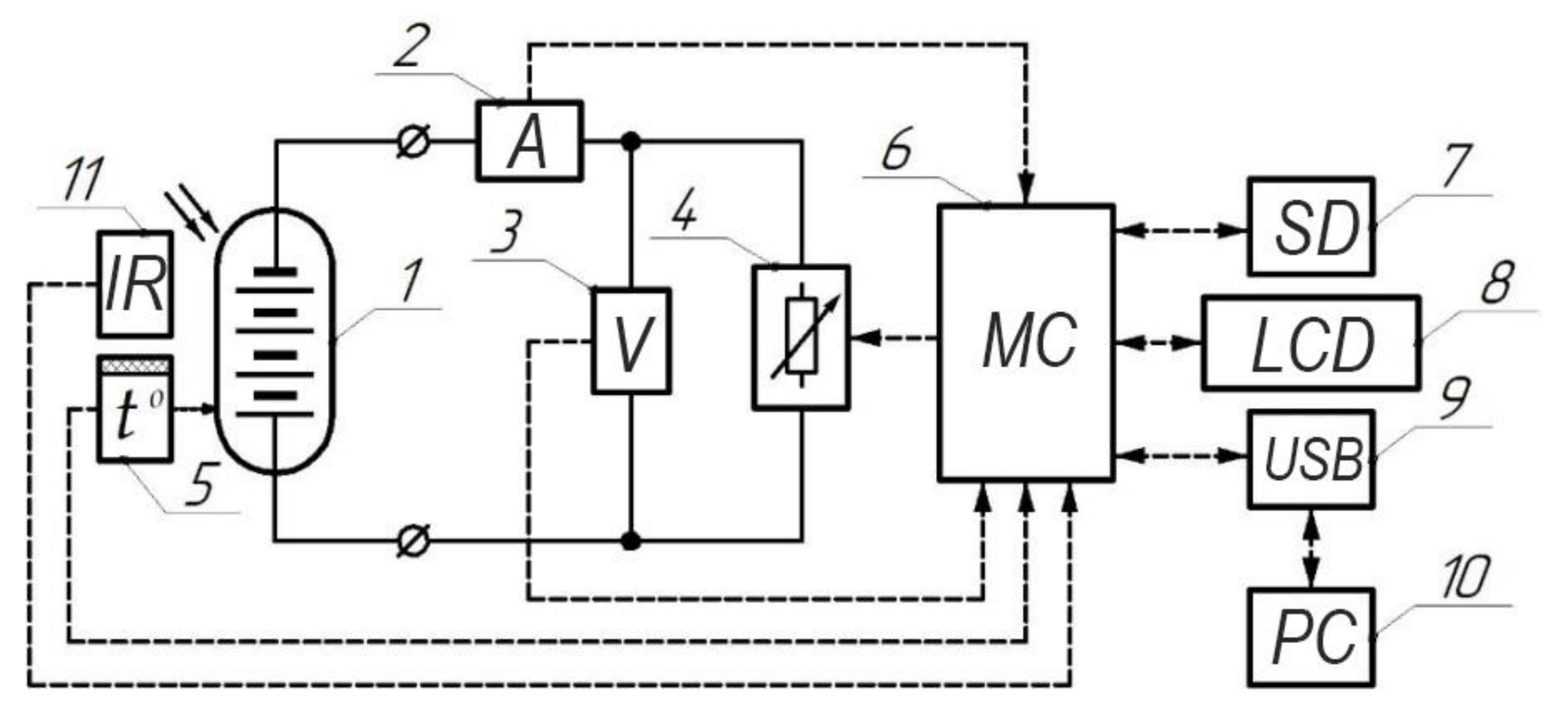
2. Materials and Methods
3. Efficiency Estimation of PV Installation
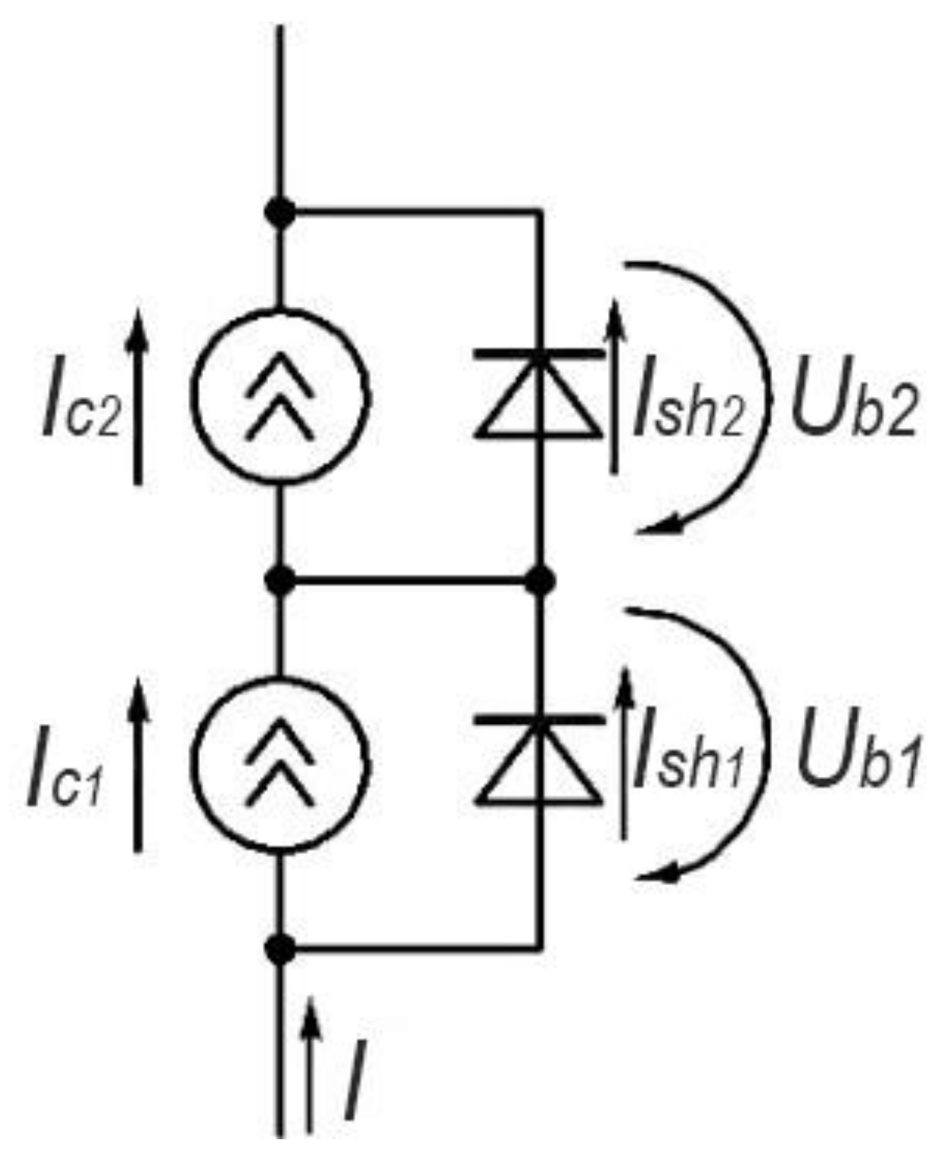
3.1. PV Installation with Shunt Diodes
- -
- shutdown of a sufficiently large group of solar cells (having partial or complete shading), despite the fact that they are almost always still capable of generating electrical energy;
- -
- decreasing the voltage at the point of maximum power of the entire array of solar cells, which leads to a significant decrease in its energy efficiency when arrays are connected in parallel or when using an inverter with an input voltage range value exceeding this value.
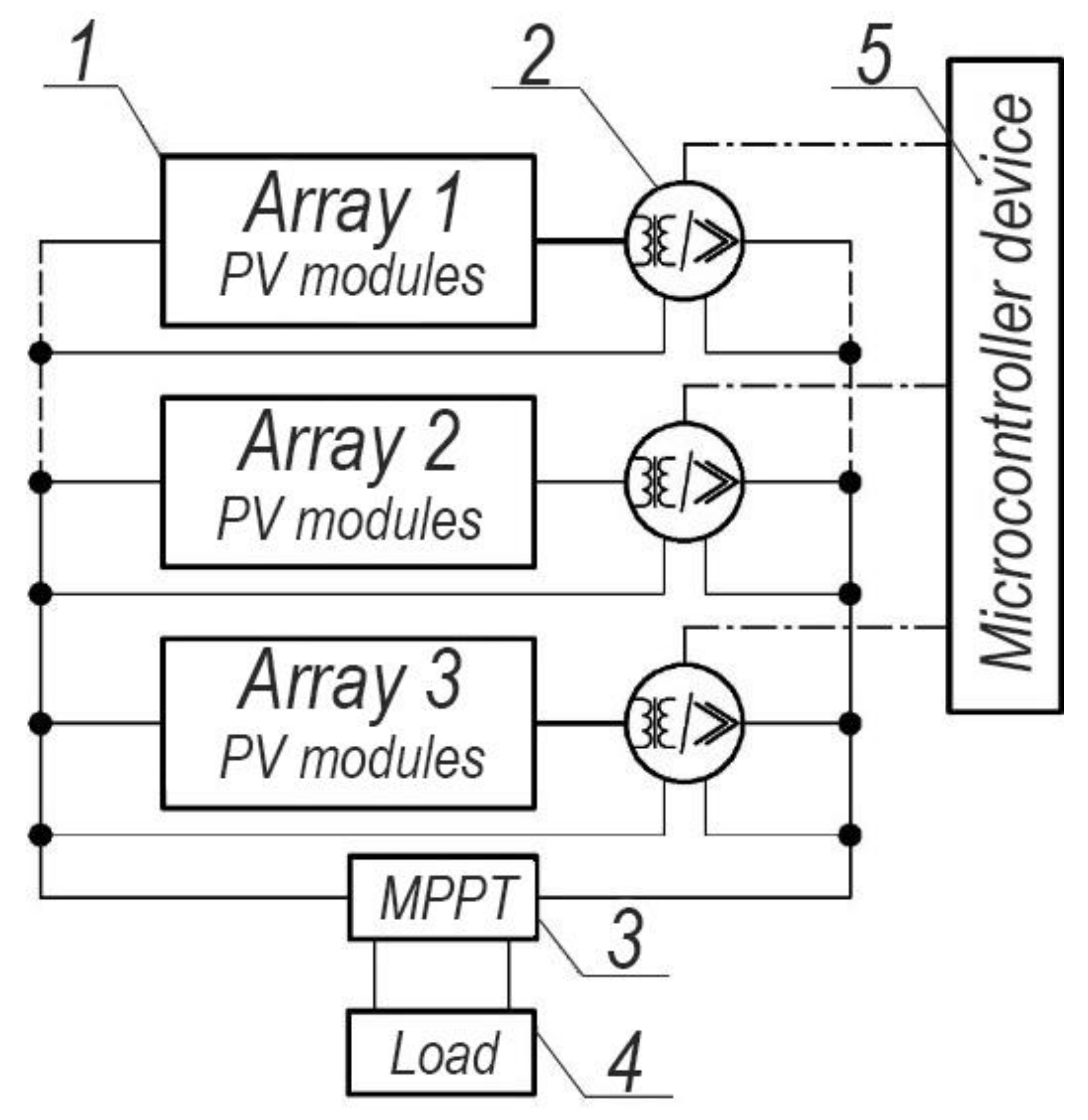
3.2. PV Installation with Individual Matching Converters and Micro-Inverters
- -
- a significant increase in the cost of the installation (the cost of the ICP is about 15–20% of the cost of the module);
- -
- reduction of the voltage value of the entire array of PV modules at the point of maximum power, which, as in the case of shunt diodes, significantly affects the energy efficiency during parallel switching of arrays.
- 1.
- High cost. The use of micro-inverters instead of the central one in industrial power plants is on average 50–85% more expensive.
- 2.
- Lack of possibility of implementation in existing power plants with a central inverter to solve the problem of uneven illumination.
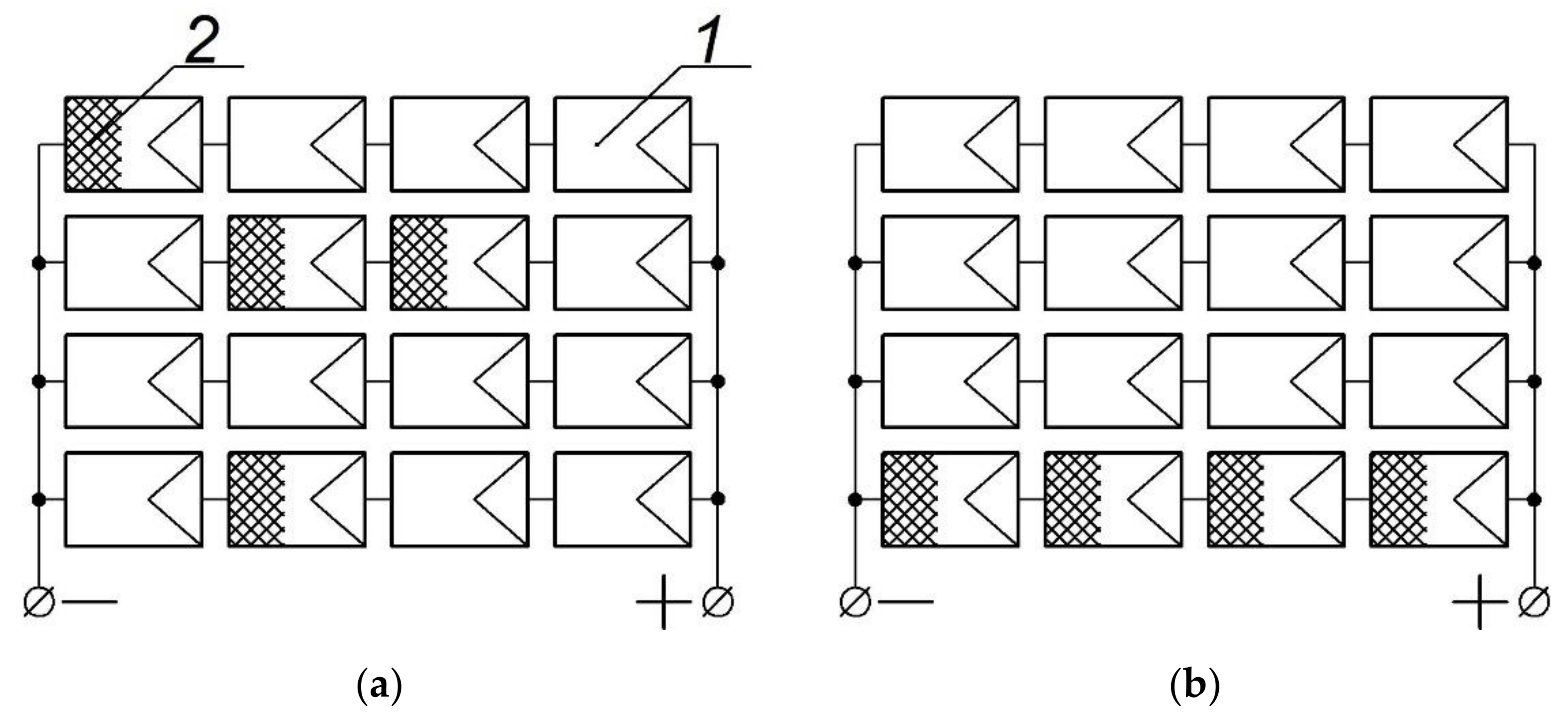
3.3. PV Installation with Reconfigurable Switching Systems
- -
- practical complexity of the method implementation in industrial solar power plants;
- -
- high cost, justified by the use of expensive switching matrices and a large number of connecting wires designed for a current of at least 10 A;
- -
- inefficiency with a small number of shaded solar modules.
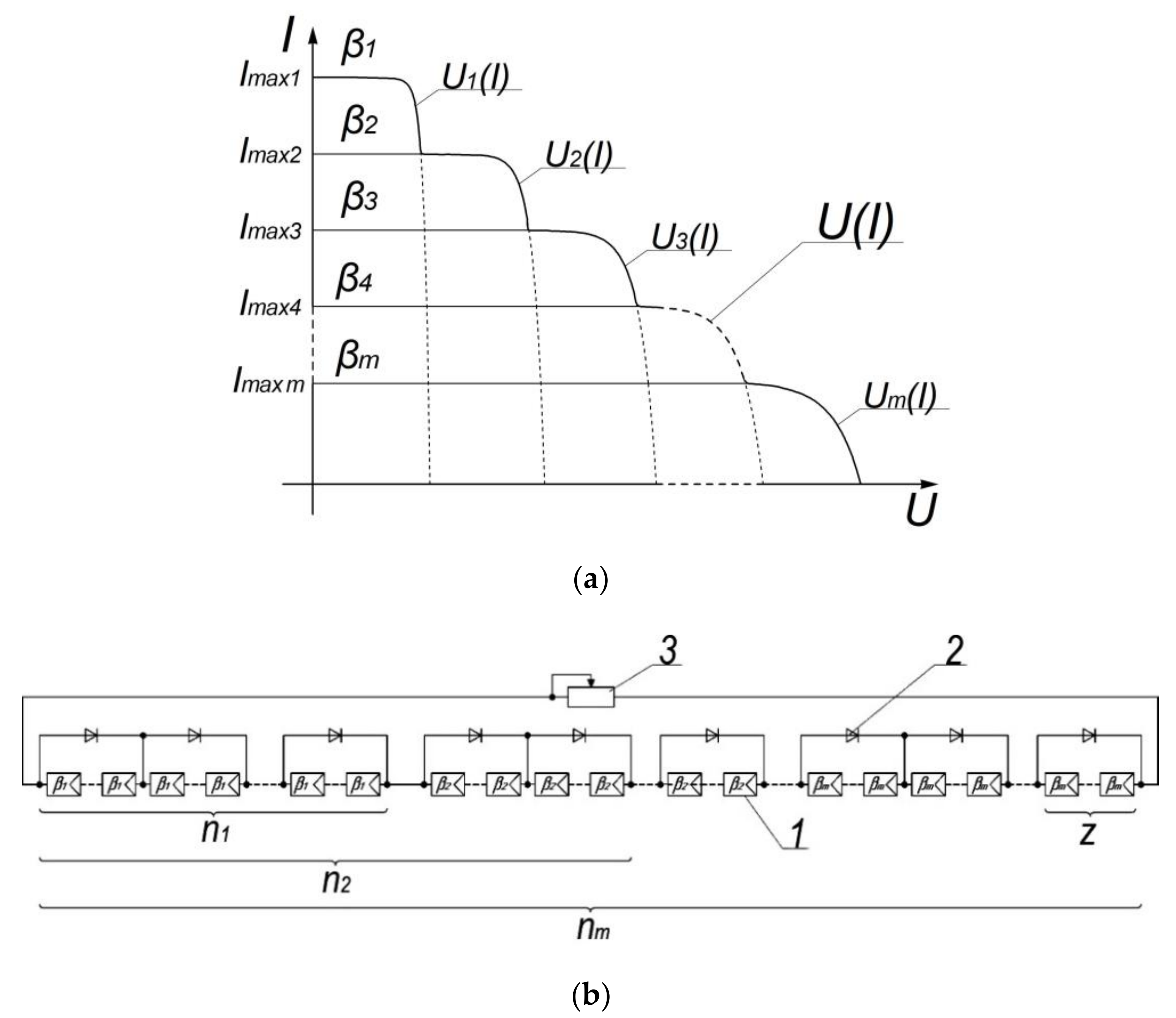
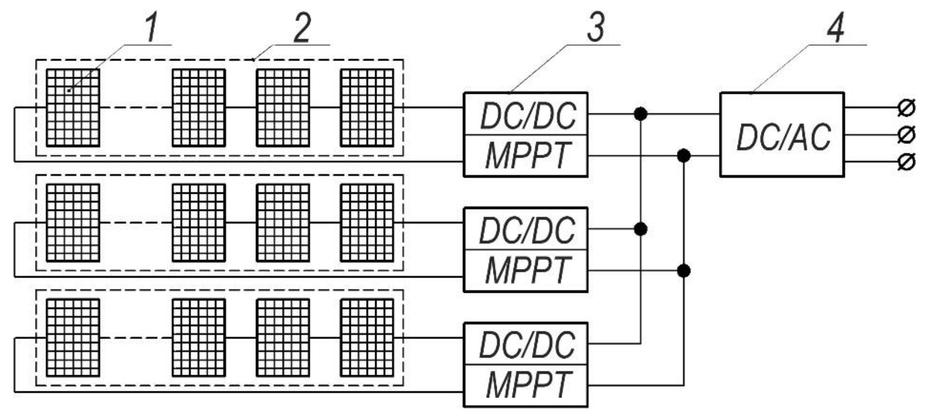
3.4. PV Installation with Differentiated Maximum Power Take-Off Systems
- -
- high cost and material consumption due to the fact that the stabilizers used are designed for power with a value not lower than the nominal power of the array of modules in which they are installed;
- -
- decrease in energy efficiency due to the fact that, for voltage matching, all the energy generated by the array is converted. Thus, the output power is reduced by the amount of efficiency of the stabilizers.
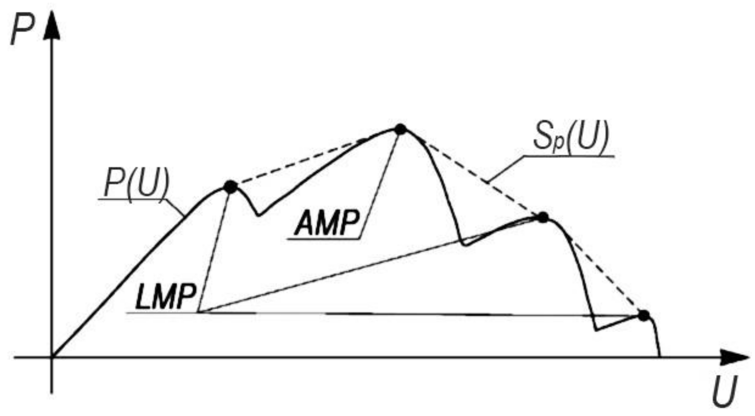
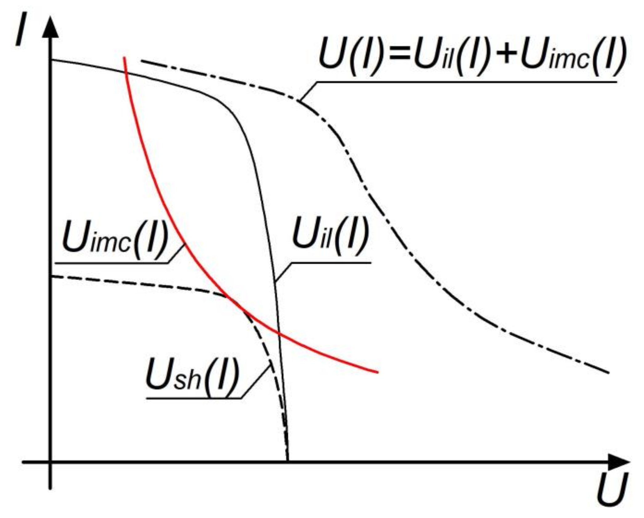
3.5. Proposed Method of Matching PV Modules with Mixed Commutation under Partial Shading
4. Discussion
5. Conclusions
Author Contributions
Funding
Institutional Review Board Statement
Informed Consent Statement
Conflicts of Interest
References
- Kannan, N.; Vakeesan, D. Solar energy for future world: - A review. Renew. Sustain. Energy Rev. 2016, 62, 1092–1105. [Google Scholar] [CrossRef]
- Tiwari, G.N.; Tiwari, A. Handbook of Solar Energy; Springer: Singapore, 2016. [Google Scholar]
- Kuznetsov, P.N.; Safonov, V.A. Improving the efficiency of the photovoltaic plant. Energy. Secur. Energy Sav. 2016, 3, 26–30. [Google Scholar]
- Kuznetsov, P.N.; Yuferev, L.Y. Increasing the efficiency of photovoltaic converters when connected in series. VIESH Bull. 2017, 1, 90–97. [Google Scholar]
- Alonso-Garcia, M.C.; Ruiz, J.M.; Chenlo, F. Experimental study of mismatch and shading effects in the I–V charac-teristic of a photovoltaic module. Sol. Energy Mater. Sol. Cells 2006, 90, 329–340. [Google Scholar] [CrossRef]
- Teo, J.C.; Tan, R.H.; Mok, V.H.; Ramachandaramurthy, V.K.; Tan, C. Impact of partial shading on the PV charac-teristics and the maximum power of a photovoltaic string. Energies 2018, 11, 1860. [Google Scholar] [CrossRef] [Green Version]
- Krishna, G.S.; Moger, T. Reconfiguration strategies for reducing partial shading effects in photovoltaic arrays: State of the art. Sol. Energy 2019, 182, 429–452. [Google Scholar] [CrossRef]
- Li, H.; Yang, D.; Su, W.; Lü, J.; Yu, X. An overall distribution particle swarm optimization MPPT algorithm for pho-tovoltaic system under partial shading. IEEE Trans. Ind. Electron. 2018, 66, 265–275. [Google Scholar] [CrossRef]
- Chaibi, Y.; Malvoni, M.; Chouder, A.; Boussetta, M.; Salhi, M. Simple and efficient approach to detect and diagnose electrical faults and partial shading in photovoltaic systems. Energy Convers. Manag. 2019, 196, 330–343. [Google Scholar] [CrossRef]
- Belhachat, F.; Larbes, C. A review of global maximum power point tracking techniques of photovoltaic system under partial shading conditions. Renew. Sustain. Energy Rev. 2018, 92, 513–553. [Google Scholar] [CrossRef]
- Kuznetsov, P.N.; Ali, L.A.; Kuvshinov, V.V.; Issa, H.A.; Mohammed, H.J.; Al-Bairmani, A.G. Investigation of the losses of photovoltaic solar systems during operation under partial shading. J. Appl. Eng. Sci. 2020, 18, 313–320. [Google Scholar] [CrossRef]
- Kharchenko, V.; Nikitin, B.; Tikhonov, P.; Panchenko, V.; Vasant, P. Evaluation of the Silicon Solar Cell Parameters. In Proceedings of the International Conference on Intelligent Computing & Optimization, Pattaya, Thailand, 4–5 October 2018; Springer: Cham, Switzerland, 2018; pp. 328–336. [Google Scholar]
- Panchenko, V.; Izmailov, A.; Kharchenko, V.; Lobachevskiy, Y. Photovoltaic Solar Modules of Different Types and Designs for Energy Supply. Int. J. Energy Optim. Eng. 2020, 9, 74–94. [Google Scholar] [CrossRef]
- Panchenko, V. Roofing Solar Panels of Planar and Concentrator Designs. Int. J. Energy Optim. Eng. 2020, 9, 20–40. [Google Scholar] [CrossRef]
- Sampaio, P.G.V.; González, M.O.A. Photovoltaic solar energy: Conceptual framework. Renew. Sustain. Energy Rev. 2017, 74, 590–601. [Google Scholar] [CrossRef]
- Badis, A.; Boujmil, M.H.; Mansouri, M.N. A Comparative Study on Maximum Power Point Tracking Techniques of Photovoltaic Systems. Int. J. Energy Optim. Eng. 2018, 7, 66–85. [Google Scholar] [CrossRef]
- Piasecka, I.; Bałdowska-Witos, P.; Piotrowska, K.; Tomporowski, A. Eco-Energetical Life Cycle Assessment of Materials and Components of Photovoltaic Power Plant. Energies 2020, 13, 1385. [Google Scholar] [CrossRef] [Green Version]
- Granata, G.; Pagnanelli, F.; Moscardini, E.; Havlik, T.; Toro, L. Recycling of photovoltaic panels by physical operations. Sol. Energy Mater. Sol. Cells 2014, 123, 239–248. [Google Scholar] [CrossRef]
- Rasheed, M.; Alabdali, O.; Shihab, S. A New Technique for Solar Cell Parameters Estimation of The Single-Diode Model. J. Physics Conf. Ser. 2021, 1879, 1742–6596. [Google Scholar] [CrossRef]
- Kumari, J.; Babu, C.S. Mathematical Modeling and Simulation of Photovoltaic Cell using Matlab-Simulink Environment. Int. J. Electr. Comput. Eng. 2011, 2, 26–34. [Google Scholar] [CrossRef]
- Saeed, M.A.; Kim, S.H.; Kim, H.; Liang, J.; Woo, H.Y.; Kim, T.G.; Yan, H.; Shim, J.W. Indoor Organic Photovoltaics: Optimal Cell Design Principles with Synergistic Parasitic Resistance and Optical Modulation Effect. Adv. Energy Mater. 2021, 11, 27. [Google Scholar] [CrossRef]
- Hua, C.; Shen, C. Study of maximum power tracking techniques and control of DC/DC converters for photovoltaic power system. In Proceedings of the 29th Annual IEEE Power Electronics Specialists Conference (Cat. No.98CH36196), Fukuoka, Japan, 22 May 2002; PESC 98 Record. Volume 1, pp. 86–93. [Google Scholar] [CrossRef]
- Meyer, E.L. Extraction of Saturation Current and Ideality Factor from Measuring Voc and Isc of Photovoltaic Modules. Int. J. Photoenergy 2017, 2017, 8479487. [Google Scholar] [CrossRef] [Green Version]
- Tsai, H.L.; Tu, C.S.; Su, Y.J. Development of generalized photovoltaic model using MATLAB/SIMULINK. In Proceedings of the World Congress on Engineering and Computer Science, San Francisco, CA, USA, 22–24 October 2008; pp. 1–6. [Google Scholar]
- Rauschenbach, H.S. Solar Cell Array Design Handbook: The Principles and Technology of Photovoltaic Energy Conversion; Springer Science & Business Media: Berlin/Heidelberg, Germany, 2012. [Google Scholar]
- Dhimish, M.; Holmes, V.; Mather, P.; Sibley, M. Novel hot spot mitigation technique to enhance photovoltaic solar panels output power performance. Sol. Energy Mater. Sol. Cells 2018, 179, 72–79. [Google Scholar] [CrossRef] [Green Version]
- Takagiwa, Y.; Shinohara, Y. A practical appraisal of thermoelectric materials for use in an autonomous power supply. Scr. Mater. 2019, 172, 98–104. [Google Scholar] [CrossRef]
- Wen, Z.; Chen, J.; Cheng, X.; Niu, H.; Luo, X. A new and simple split series strings approach for adding bypass diodes in shingled cells modules to reduce shading loss. Sol. Energy 2019, 184, 497–507. [Google Scholar] [CrossRef]
- Vieira, R.; de Araújo, F.; Dhimish, M.; Guerra, M. A Comprehensive Review on Bypass Diode Application on Photovoltaic Modules. Energies 2020, 13, 2472. [Google Scholar] [CrossRef]
- Laamami, S.; Abid, A.; Benhamed, M.; Sbita, L. Investigation on Protection Diodes in PV Generator. In Proceedings of the 2020 17th International Multi-Conference on Systems, Signals & Devices (SSD), Monastir, Tunisia, 20–23 July 2020; IEEE: Piscataway, NJ, USA, 2020; pp. 1069–1073. [Google Scholar]
- Gallardo-Saavedra, S.; Karlsson, B. Simulation, validation and analysis of shading effects on a PV system. Sol. Energy 2018, 170, 828–839. [Google Scholar] [CrossRef]
- Çelik, Ö.; Tan, A.; Inci, M.; Teke, A. Improvement of energy harvesting capability in grid-connected photovoltaic mi-cro-inverters. Energy Sources Part A Recover Util. Environ. Eff. 2020, 1–25. [Google Scholar] [CrossRef]
- Falconar, N.; Beyragh, D.S.; Pahlevani, M. A novel control system for solar tile micro-inverters. In Proceedings of the 2018 IEEE Applied Power Electronics Conference and Exposition (APEC), Phoenix, AZ, USA, 4–8 March 2018; IEEE: Piscataway, NJ, USA, 2018; pp. 375–380. [Google Scholar]
- Kabalcı, E. Review on novel single-phase grid-connected solar inverters: Circuits and control methods. Sol. Energy 2020, 198, 247–274. [Google Scholar] [CrossRef]
- Yuan, J.; Blaabjerg, F.; Yang, Y.; Sangwongwanich, A.; Shen, Y. An Overview of Photovoltaic Microinverters: Topology, Efficiency, and Reliability. In Proceedings of the 2019 IEEE 13th International Conference on Compatibility, Power Electronics and Power Engineering (CPE-POWERENG), Sonderborg, Denmark, 23–25 April 2019; pp. 1–6. [Google Scholar]
- Zhang, Z.; He, X.-F.; Liu, Y.-F. An Optimal Control Method for Photovoltaic Grid-Tied-Interleaved Flyback Microinverters to Achieve High Efficiency in Wide Load Range. IEEE Trans. Power Electron. 2013, 28, 5074–5087. [Google Scholar] [CrossRef]
- Gao, W.X.; Wang, M.Y.; Wang, L.J.; Liu, Y. Review of research on photovoltaic micro-inverter. Power Syst. Prot. Contrl. 2012, 40, 147–155. [Google Scholar]
- Gazis, F.S.; Vokas, G.A.; Katsimardou, I.J.; Kaldelis, J.K. Micro inverters for PV plants compared to the ordinary string or central inverters. In Proceedings of the Conference for International Synergy in Energy, Environment, Tourism and Contribution of Information Technology in Science, Economy, Society and Education, Piraeus, Greece, 23–25 September 2013; pp. 1–9. [Google Scholar]
- Christabel, S.C.; Srinivasan, A.; Winston, D.P.; Kumar, B.P. Reconfiguration solution for extracting maximum power in the aged solar PV systems. J. Electrl. Eng. 2016, 16, 440–446. [Google Scholar]
- Deshkar, S.N.; Dhale, S.B.; Mukherjee, J.S.; Babu, T.S.; Rajasekar, N. Solar PV array reconfiguration under partial shading conditions for maximum power extraction using genetic algorithm. Renew. Sustain. Energy. Rev. 2015, 43, 102–110. [Google Scholar] [CrossRef]
- Lee, H.-S.; Yun, J.-J. Advanced MPPT Algorithm for Distributed Photovoltaic Systems. Energies 2019, 12, 3576. [Google Scholar] [CrossRef] [Green Version]
- Lee, J.-H.; You, Y.-J.; Saeed, M.A.; Kim, S.H.; Choi, S.-H.; Kim, S.; Lee, S.Y.; Park, J.-S.; Shim, J.W. Undoped tin dioxide transparent electrodes for efficient and cost-effective indoor organic photovoltaics (SnO2 electrode for indoor organic photovoltaics). NPG Asia Mater. 2021, 13, 43. [Google Scholar] [CrossRef]


| Material | Coefficient A |
|---|---|
| Si—monocrystalline | 1.2 |
| Si—polycrystalline | 1.3 |
| a-Si:H—amorphous hydrogenated | 1.8 |
| a-Si:H double | 3.3 |
| a-Si:H triple | 5 |
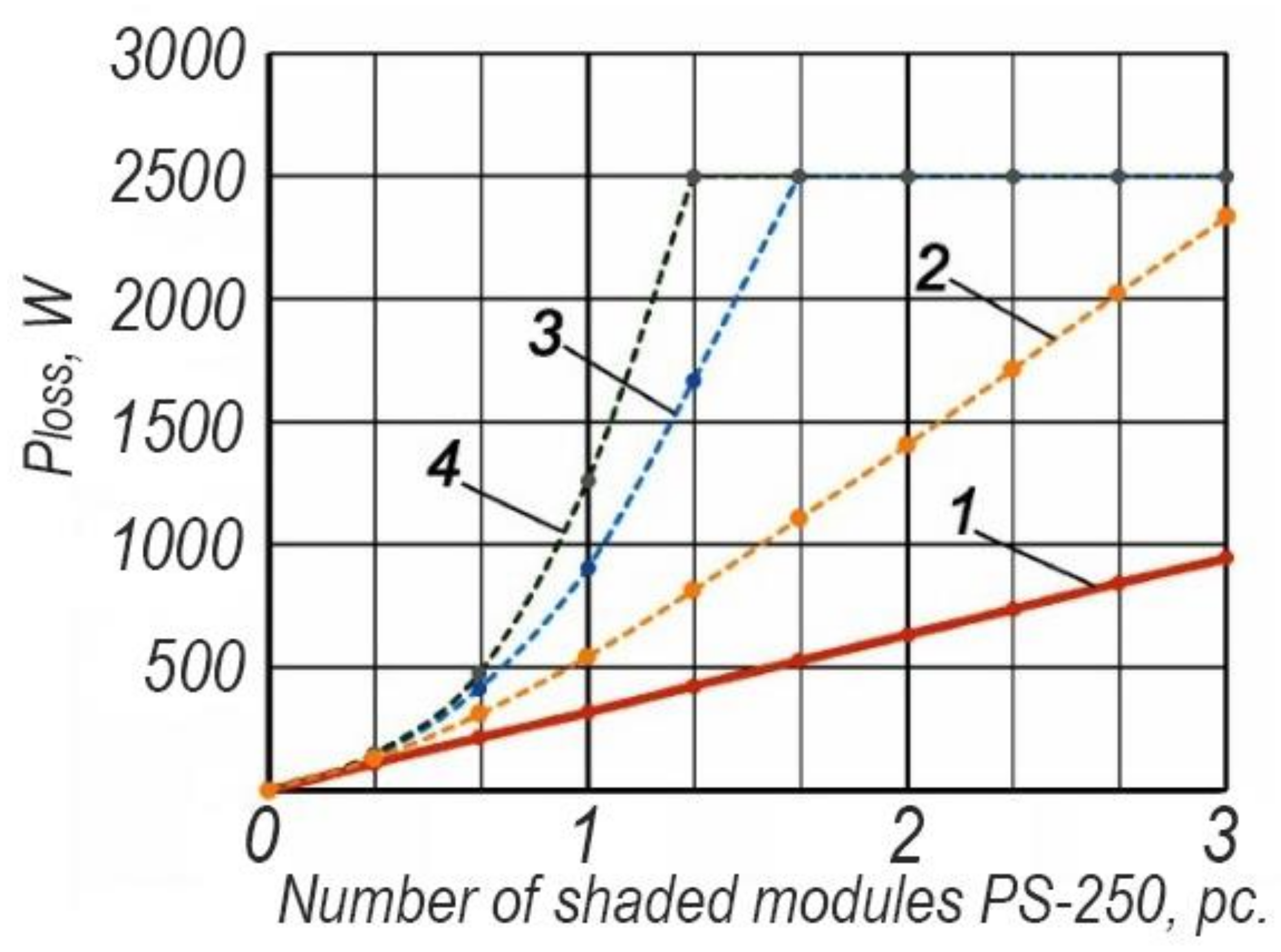
| Number of Shaded Modules in the Array | Output Power of the PV Array Using APE Method (W) | Output Power of the PV Array Using IMC Method (W) | Output Power of the PV Array Using the Method “Differentiated Maximum Power Take-Off Systems” (W) | Output Power of the PV Array without Additional Methods (W) |
|---|---|---|---|---|
| 0 | 2500 | 2500 | 2500 | 2500 |
| 1 | 2230 | 1970 | 2050 | 1650 |
| 2 | 1850 | 1100 | 1790 | 100 |
| 3 | 1500 | 250 | 1460 | 100 |
Publisher’s Note: MDPI stays neutral with regard to jurisdictional claims in published maps and institutional affiliations. |
© 2021 by the authors. Licensee MDPI, Basel, Switzerland. This article is an open access article distributed under the terms and conditions of the Creative Commons Attribution (CC BY) license (https://creativecommons.org/licenses/by/4.0/).
Share and Cite
Kuznetsov, P.; Yuferev, L.; Voronin, D.; Panchenko, V.A.; Jasiński, M.; Najafi, A.; Leonowicz, Z.; Bolshev, V.; Martirano, L. Methods Improving Energy Efficiency of Photovoltaic Systems Operating under Partial Shading. Appl. Sci. 2021, 11, 10696. https://doi.org/10.3390/app112210696
Kuznetsov P, Yuferev L, Voronin D, Panchenko VA, Jasiński M, Najafi A, Leonowicz Z, Bolshev V, Martirano L. Methods Improving Energy Efficiency of Photovoltaic Systems Operating under Partial Shading. Applied Sciences. 2021; 11(22):10696. https://doi.org/10.3390/app112210696
Chicago/Turabian StyleKuznetsov, Pavel, Leonid Yuferev, Dmitry Voronin, Vladimir A. Panchenko, Michał Jasiński, Arsalan Najafi, Zbigniew Leonowicz, Vadim Bolshev, and Luigi Martirano. 2021. "Methods Improving Energy Efficiency of Photovoltaic Systems Operating under Partial Shading" Applied Sciences 11, no. 22: 10696. https://doi.org/10.3390/app112210696