Article

Highly Efficient Transformerless Inverter with Flying-Capacitor Buck–Boost for Single-Phase Grid-Connected PV Systems

1
Department of Electrical and Computer Engineering, Faculty of Engineering, King Abdulaziz University, Jeddah 21481, Saudi Arabia
2
Center of Research Excellence in Renewable Energy and Power Systems, King Abdulaziz University, Jeddah 21481, Saudi Arabia
*
Author to whom correspondence should be addressed.
Appl. Sci. 2021, 11(22), 10841; https://doi.org/10.3390/app112210841
Submission received: 24 September 2021 / Revised: 2 November 2021 / Accepted: 5 November 2021 / Published: 17 November 2021

Abstract

:
Grid-connected inverters (GCI) are commonly used in PV system applications to generate a regulated AC current to feed into the grid. Transformerless inverters are the most advanced inverters that are used in industry, which provide efficiency with smaller size and lower cost. This paper proposes a grid-connected single-phase transformerless inverter with the technology of common ground and the virtual DC bus concept. In this topology, the grid neutral is connected directly to the PV ground, which generates a constant common mode voltage (CMV), thus leading to the elimination of the leakage current caused by the PV array’s parasitic capacitance. The proposed inverter has a buck–boost circuit with a flying capacitor to generate the DC bus for a negative power cycle, four switches, and two diodes. A unipolar sinusoidal pulse width modulation (SPWM) technique is used which reduces the output filter requirements. In addition, only one switch carries the load current during the active states of both the negative and positive power cycle, thus minimizing the conduction losses. One more advantage presented in the proposed inverter is its ability to charge the flying capacitor during all operation states due to the existence of the buck–boost circuit. Design and theoretical calculations were conducted in this paper to optimize the losses. Moreover, the PSIM simulation was used to validate the proposed topology inverter, verify the performance by showing leakage current elimination, and achieve unipolar voltage in the output bus. The simulation results show a peak efficiency of 98.57% for a 2 kW inverter, which agrees with the theoretical calculations.

1. Introduction

In recent decades, the growth in renewable energy systems has increased exponentially. Therefore, governments and national planning makers tend towards generating electricity based on renewable resources instead of conventional electricity resources. In 2020, 80% of the new installed capacity of electricity was from renewable resources, and 91% of that was wind and solar energy [1]. Moreover, in 2017 the nominal peak power installed worldwide of solar PV was almost 405 GW, and wind energy installation was approximately 540 GW [2]. Obviously, the world tends to depend on renewable energy resources because of its reliability and environmentally friendly features, especially with the increased awareness towards global warming issues. Due to the rapid increase in the demand for clean energy, the utilization of the distributed generation (DG) by renewable energy resources has increased quickly, which has led to enhanced inverters technology to reduce the effects of the grid stability [3]. The residential PV systems are classified as stand-alone PV systems (off-grid) or grid-connected PV systems [4].
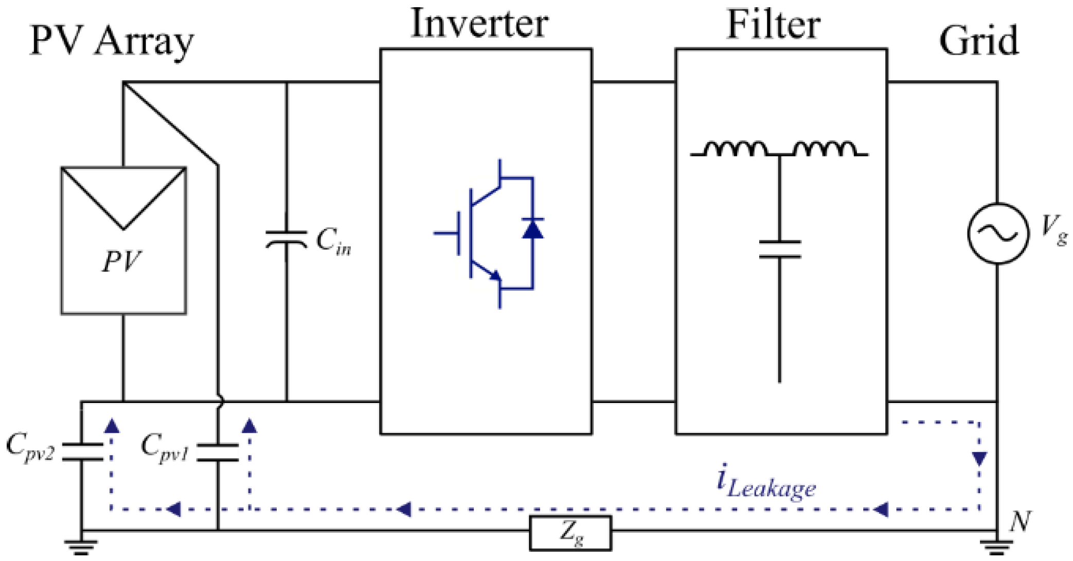
PV systems require an inverter in order to interface between the PV panels and the grid. The inverters are classified into galvanic isolated inverters and non-isolated inverters. In isolated inverters, the isolation can be achieved by a high-frequency DC side transformer or a low-frequency AC side transformer. The galvanic isolation serves to improve the overall system safety to achieve the corresponding safety standards required for grid-tied PV systems; at the same time, these transformers lead to bulky inverters with higher cost and lower efficiency [5,6]. Recently, for the residential market, transformerless inverters have been utilized due to their lower cost, higher efficiency, and smaller size [7]. The basic structure for the transformerless inverter was first presented in 1956 by McMurray, where he developed the Full Bridge FB or H-Bridge inverter family for the first time. The structure of an FB inverter can be seen in Figure 1 [8].
The H-Bridge structure has many drawbacks regarding safety; one limitation is the leakage current produced by the parasitic capacitance formed between PV panels and the ground. The leakage current is generated by the variation in common mode voltage (CMV), which leads to high leakage current and high electromagnetic interference (EMI) [9,10,11].
According to the VDE 0.126-1-1 standard, a leakage current over 30 mA must trigger a break within 0.3 s, while the leakage current range should not be more than 100 mA and the fault breaking time should not be more than 40 ms, as shown in Table 1 [12,13]. Additionally, the leakage current can be decreased by the type of modulation [14]. The leakage current path is shown in Figure 2, where I L e a k a g e is the leakage current, C p v the parasitic capacitance and C i n the DC bust coupling capacitor.
Many transformerless inverter topologies have been proposed in the literature to increase the efficiency by reducing conduction losses, decreasing the CMV to satisfy grid requirements, and decreasing the number of components to reduce the costs and size [15]. One proposed inverter, called the neutral point clamped (NPC), which reduces the filter requirement, leakage current, and EMI, and a modified type of NPC called the Active NPC (ANPC), mitigate the limitations of NPC topology [16,17]. In 2005, SMA proposed a new inverter topology called H5, which reduces CMV through eliminating the high-frequency component of CMV by detaching the power grid from the PV module during the zero-voltage state [18]. Another popular transformerless inverter is the HERIC (Highly Efficient and Reliable Inverter Concept) inverter, developed by Sunways in 2006. It consists of six switches and is based on the AC decoupling method in order to isolate the output inductor filter from the PV panel parasitic capacitance and achieve unipolar SPWM [15]. Therefore, this topology leads to reduced leakage current and EMI, increasing the efficiency and reducing the size [19]. A new type of inverter with the theoretical elimination of the leakage current derived from the conventional H6 inverter was proposed in [20].
Another transformerless topology based on the common ground technology is introduced, which connects the grid ground to the PV panels ground permanently, resulting in constant CMV. Therefore, according to the capacitor current equation, the leakage current will be eliminated completely.
i C M = C P V × d v d t
where i C M is the common mode leakage current, C P V is the parasitic capacitance of the PV panel, and d v d t is the voltage variation across the parasitic capacitance. Based on the common ground method, a new concept was proposed in [6] in 2013, called the virtual DC bus, which is created by a flying capacitor. The virtual DC voltage supplies the negative current to the grid, while the positive current flows to the grid directly from the PV panel. However, in this topology, there are two or more switches in series during the active state which increases conduction losses and requires a relatively large capacitor, because it is charged only during the positive power cycle. A flying inductor inverter named after “Karschny” was proposed as a patent in [21], but it has no ability to deliver reactive power and is constructed with a large number of components. A new topology was proposed in [22] that charges the flying capacitor during the zero voltage state in both the positive and negative power cycle but has two extra diodes and one extra capacitor. Recently, a new topology proposed in [23] solved many of the drawbacks of previous types of transformerless inverters based on the flying capacitor, consisted of only four switches, one switch in series during active state, and proposed a modifying control method to lower the current stresses during the flying capacitor charging state. Additionally, it allows the capacitor to charge during the zero voltage state in both positive and negative power cycles, but it requires a bipolar blocking switch and still requires a relatively large capacitor.
This paper proposes a new transformerless inverter topology based on the common ground concept and virtual DC bus. The proposed transformerless inverter is constructed of a buck–boost converter, a two-switch inverter, and an extra two switches with two diodes to achieve freewheeling and the zero voltage state for unipolar SPWM. The buck–boost converter is utilized to supply the flying capacitor continuously, in all inverter operation states, with the required energy that will be utilized in the negative power cycle. The two switches deliver the power into the grid during the negative and positive power cycle and the freewheeling paths provide the output inductor freewheeling path and help in achieving a unipolar SPWM control scheme. The proposed inverter reduces conduction losses, only one switch in the current path during each active state, reducing the flying capacitor size and stresses and allowing the capacitor to charge during all operation states. Additionally, this eliminates the leakage current (theoretically) because of the common ground structure.
This paper is arranged as follows: Section 2 discusses the proposed topology and the principals of operation. Section 3 presents the operation modes and modulation technique. All design equations and main component current stresses are discussed in Section 4. Discussion and simulation results are presented in Section 5. Last, Section 6 provides the conclusion.

2. Proposed Topology and Principle of Operation

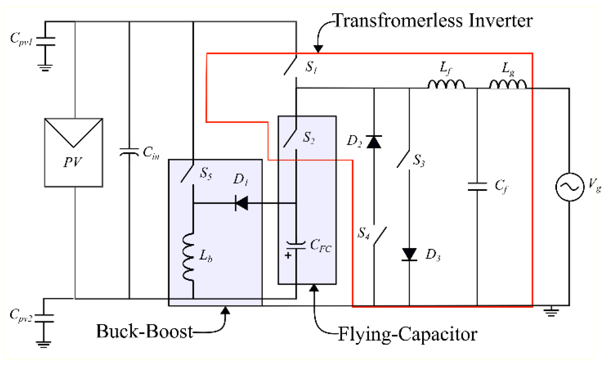
The proposed topology can be subdivided into three subcircuits as shown in Figure 3: a buck–boost converter, a common ground flying capacitor, and the transformerless inverter, which contains two main switches in addition to two freewheeling switches with series diodes to generate the required unipolar SPWM.

2.1. Buck–Boost Converter

The buck–boost converter is one of the basic converters that was used during the initial stages of the power electronics field. It works either to step-up or step-down the input voltage based on the duty cycle; if D < 0.5 the converter works in buck mode, while if D > 0.5 it presents the boost mode. It is an inverting converter in nature, where the converter output is negative with reference to the ground input. Figure 4 shows the buck–boost converter building blocks and its operation.
During the ON state, Q is closed and D is open, as illustrated in Figure 4b. The current flows from the input supply into ground through the inductor L, while the output capacitor supplies the load current during this state. Figure 4c shows that during the OFF state Q becomes open and D closes, and again the inductor nature works since the current cannot be interrupted, such that the inductor becomes a current source and the charged energy in the inductor flows to charge the output capacitor and supply the load current. This charging and discharging takes place in every switching cycle. According to the inductor volt–second law, in steady state the average voltage applied on the inductor must be zero [24,25]. Applying the volt–second balance equation, the inductor average voltage equals
V L = 1 T s 0 T s V L ( t ) = 0
V o u t V i n = D 1 D
Therefore, according to Equation (3), by controlling the duty cycle D we can generate the required inverted output voltage, which will be used in the proposed topology to charge C F C .

2.2. Common-Ground Flying Capacitor

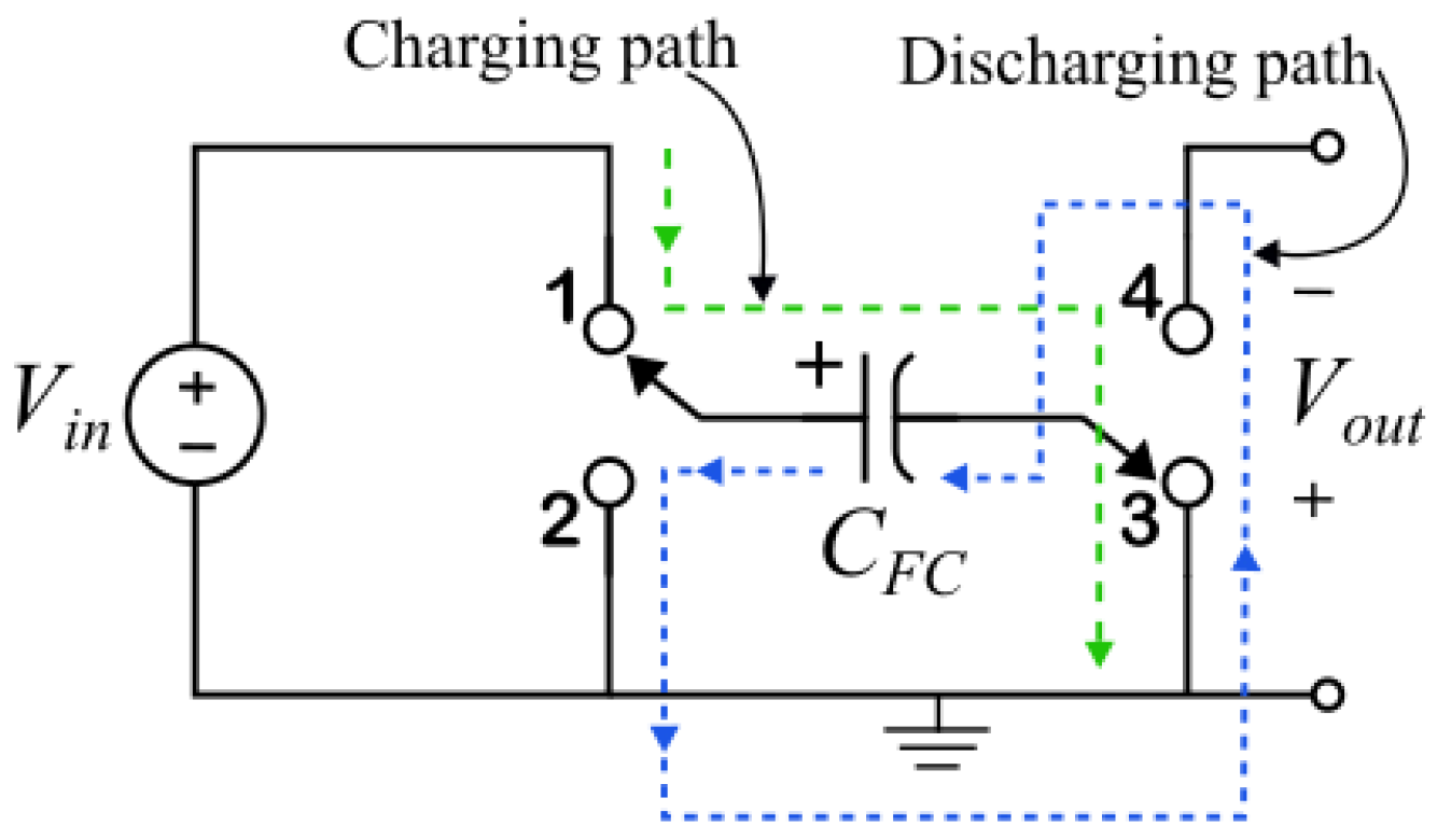
The flying capacitor concept was first introduced in DC–DC converters in a type of inductor-less converter called the charge pump (switched capacitor) DC–DC converter [26]. The basic idea behind using a flying capacitor in single-phase transformerless inverters was illustrated in [27] and is shown in Figure 5, where the capacitor is charged from the input voltage supply during a specific time by connecting the C F C positive terminal to point 1 and the negative terminal to point 3. Afterwards, the flying capacitor positive terminal is connected to point 2 and negative terminal to point 4 to release the flying capacitor from the input supply positive terminal and generate a negative output voltage source to supply the load.
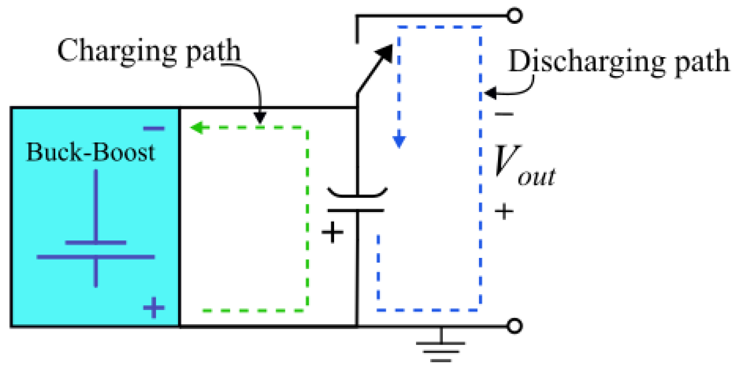
Compared with the previously mentioned flying capacitor transformerless inverter topologies, the proposed topology presents a flying capacitor that can be charged at all times from the PV panel input, despite the inverter operation state, due to introduction of a buck–boost converter, as illustrated in Figure 6. Therefore, it requires only one switch to connect or disconnect the flying capacitor negative terminal, whereas the positive terminal is connected directly. This scheme allows the flying capacitor to charge continuously at a high frequency rate. Consequently, this leads to a smaller capacitor compared with other topologies that charge C F C during the positive power cycle or freewheeling state (zero voltage state), but not during the negative power cycle (active). Moreover, this limits the charging inrush current flow into the flying capacitor due to the existence of the buck–boost inductor.

2.3. Proposed Inverter Topology

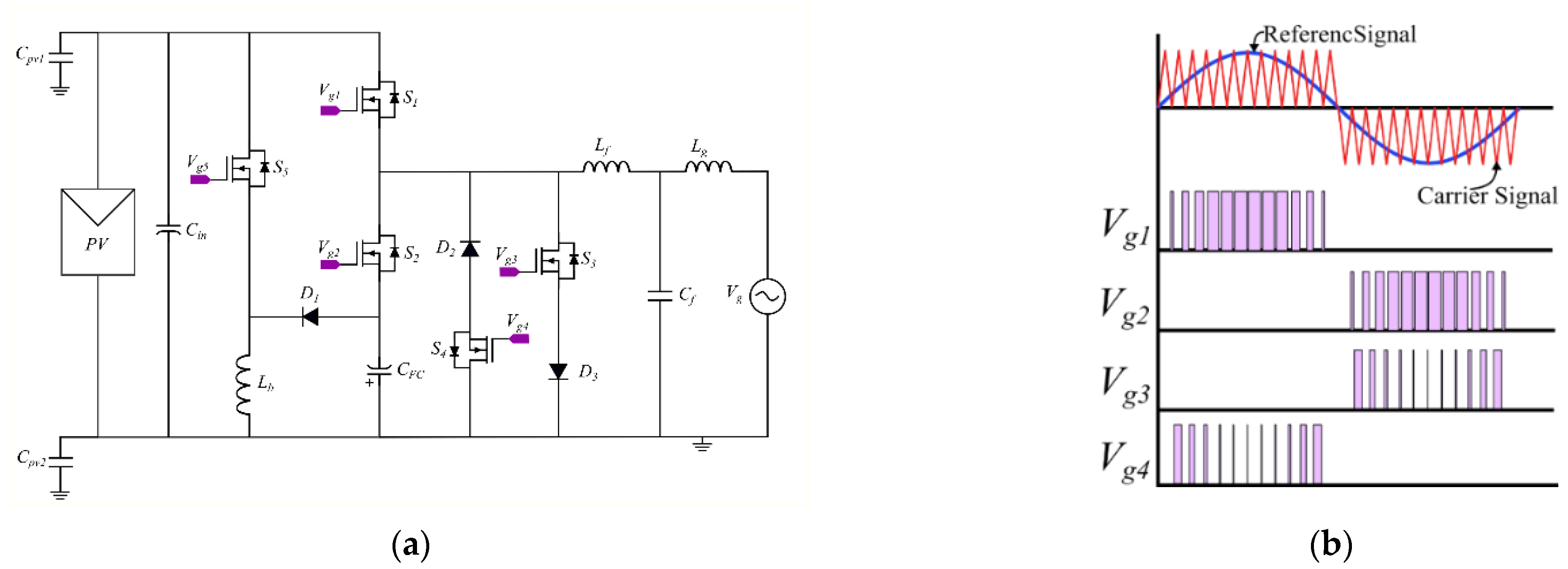
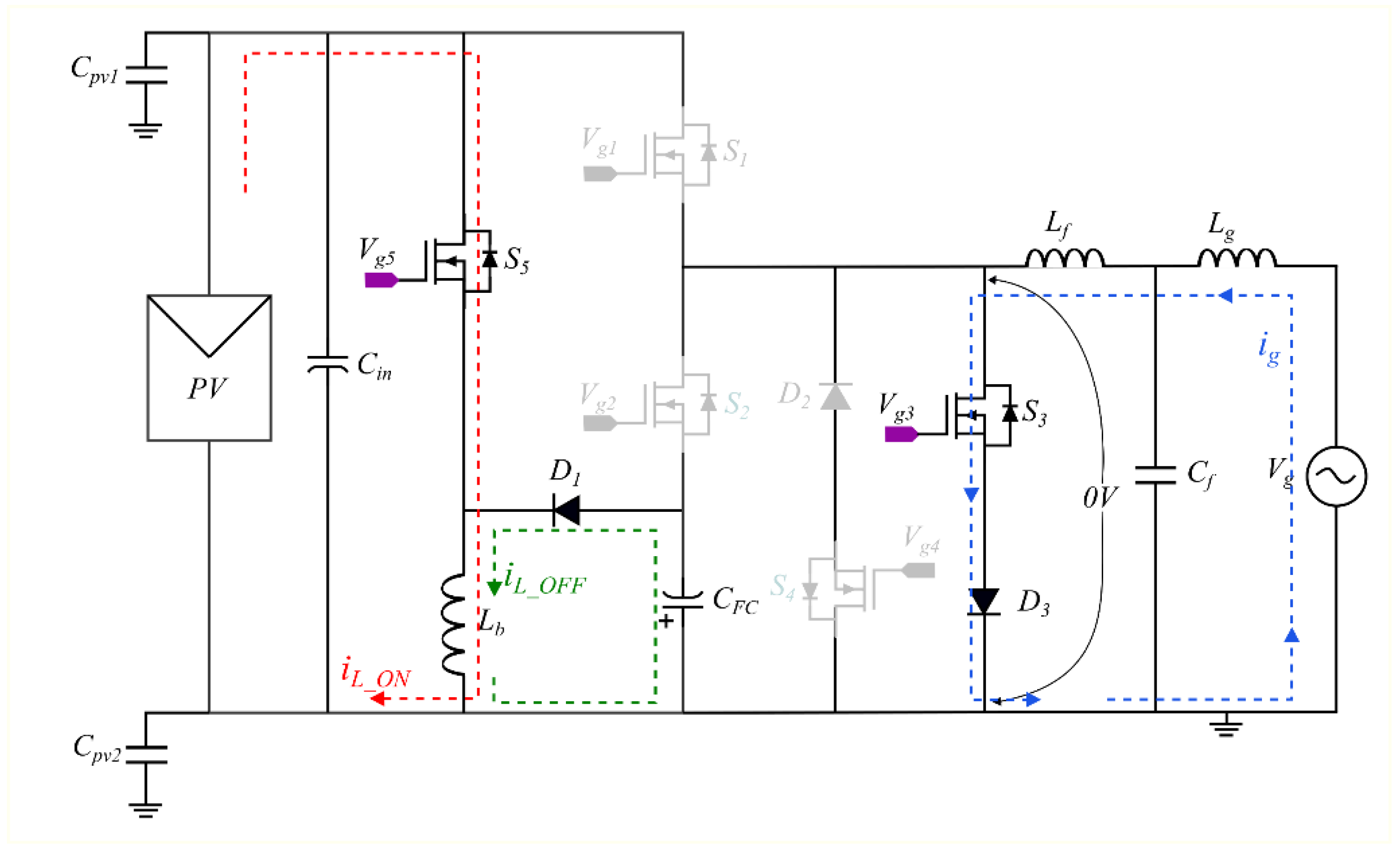
Figure 7a presents the proposed topology, which includes five power switches (S1, S2S5), three diodes (D1, D2 and D3), one inductor ( L b ) in the buck–boost configuration, and one flying capacitor ( C F C ), in addition to the input DC link capacitor ( C i n ) and output LCL filter ( L f , L g ,   C f ).
The modulation technique shown in Figure 7b illustrates that in this topology, only one switch carries the load current during each power cycle; S1 creates the positive power cycle (active state) whilst S2 creates the negative power cycle (active state). The switches S4 with D2 and S3 with D3 work in a complementary manner with S1 and S2, respectively, to achieve the zero voltage level (non-active states) in the output and allow the output inductor L f to achieve current freewheeling. Power switch S5 works continuously to supply the power from the input side to the flying capacitor, utilizing the inductor L b assisted by the diode D1 in buck–boost mode. In order to reduce the passive component sizes, MOSFET switches are adopted to achieve higher frequency. Furthermore, SiC MOSFETs can be used because of their low switching losses and fast recovery of the body diode compared with conventional Si MOSFETs. Figure 7b illustrates the unipolar SPWM modulation technique used in the proposed inverter. Two sinusoidal signals are generated by 180° phase shift between each other as a reference waves (generated from the grid voltage in grid-tied inverters) and compared with triangle signal to generate required pulses. In the unipolar SPWM scheme +Vdc, 0 and −Vdc voltage levels generated in the inverter output consequently it reduces the overall losses, required output filtration and EMI [28].

3. Operating Modes of the Proposed Inverter

As described in Section 2 the proposed topology is modulated using unipolar SPWM technique. Hence, based on that the operation of the proposed inverter is divided into positive half power cycle and negative half power cycle and each half of the power cycle has two modes of operation either active state or zero state. These four operation modes are described in this section.

3.1. Positive Cycle (Active)

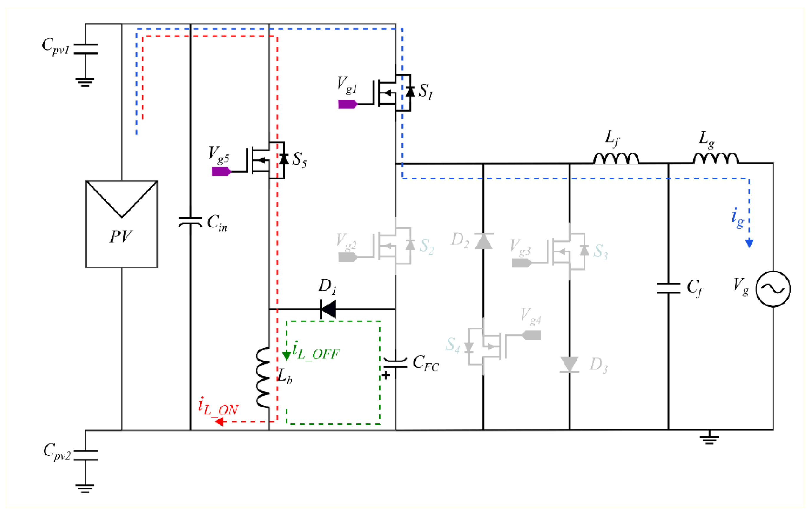
The switch S1 is switched at the gate-switching frequency generated by the modulated positive sinusoidal reference signal during the whole positive cycle. Figure 8 shows that during this state only S1 is conducted and carries the load current, while switches S2, S3, and S4 are maintained in the OFF state. Consequently, this reduces the conduction losses significantly, since only one switch in series is in the current path, represented by the blue dotted line in Figure 8. The switch S2 experience +2Vdc voltage, while the voltage across S3 is +Vdc. Furthermore, during this mode, buck–boost switch S5 conducts at high switching frequency, working as a conventional buck–boost converter with the assistance of the diode D1 and the inductor L b to precharge the flying capacitor C F C for the negative power cycle (the red dotted line presents the current path when S5 is ON ( i L _ O N ) and the green dotted line shows the current path when S5 is OFF ( i L _ O F F ) ).

3.2. Positive Cycle (Zero State)

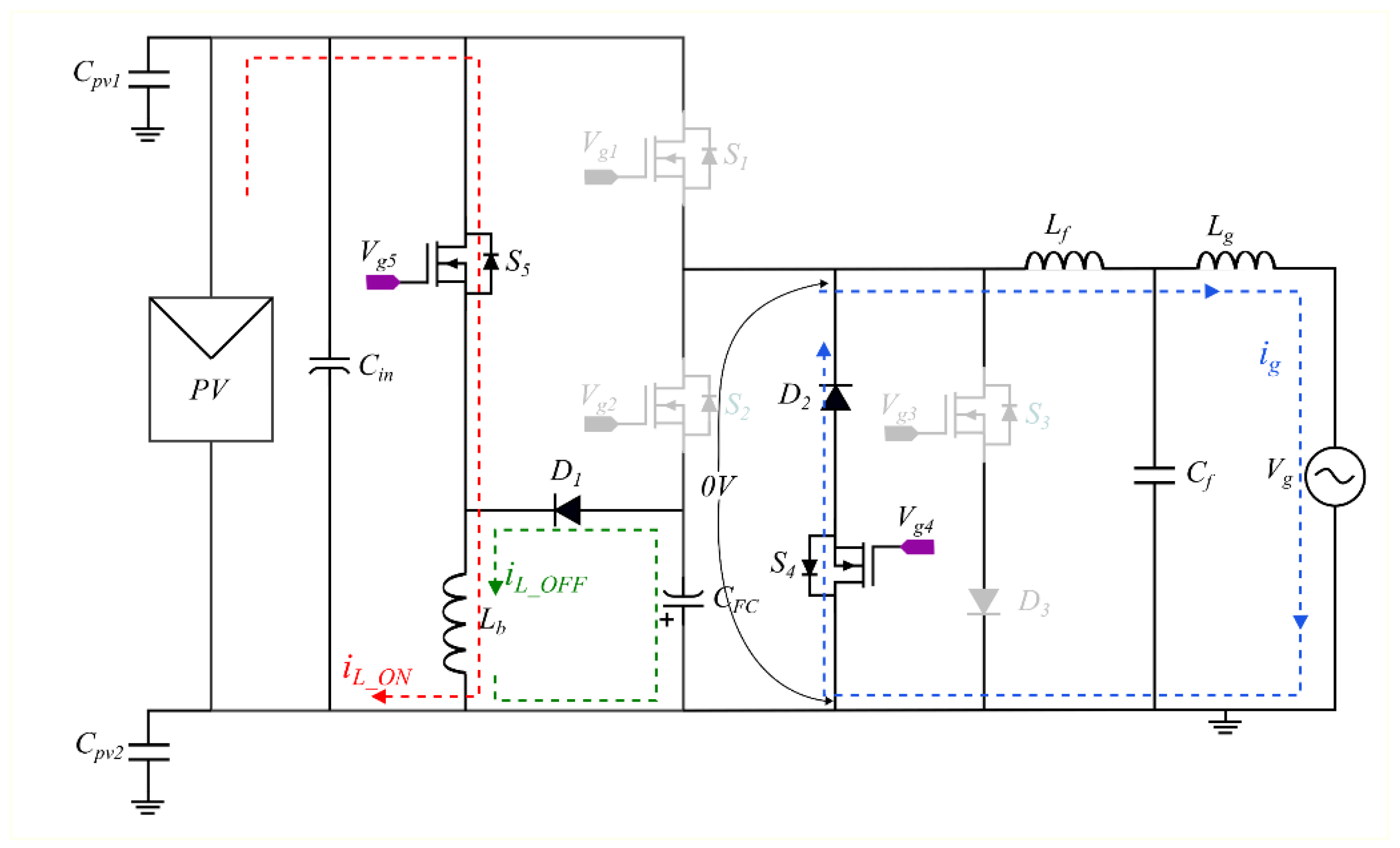
During this mode of operation, S4 and D2 conduct and S4 is ON, while S1, S2, and S3 are OFF during this operation mode. Thus, zero voltage is created across the output filter to achieve unipolar voltage across the output filter as required. This mode is illustrated in Figure 9, which shows the active devices during this mode of operation. Switches S1 and S2 experience equal voltage stresses +Vdc. The buck–boost circuit keeps running and continues charging the flying capacitor for the negative power cycle if needed.

3.3. Negative Cycle (Active)

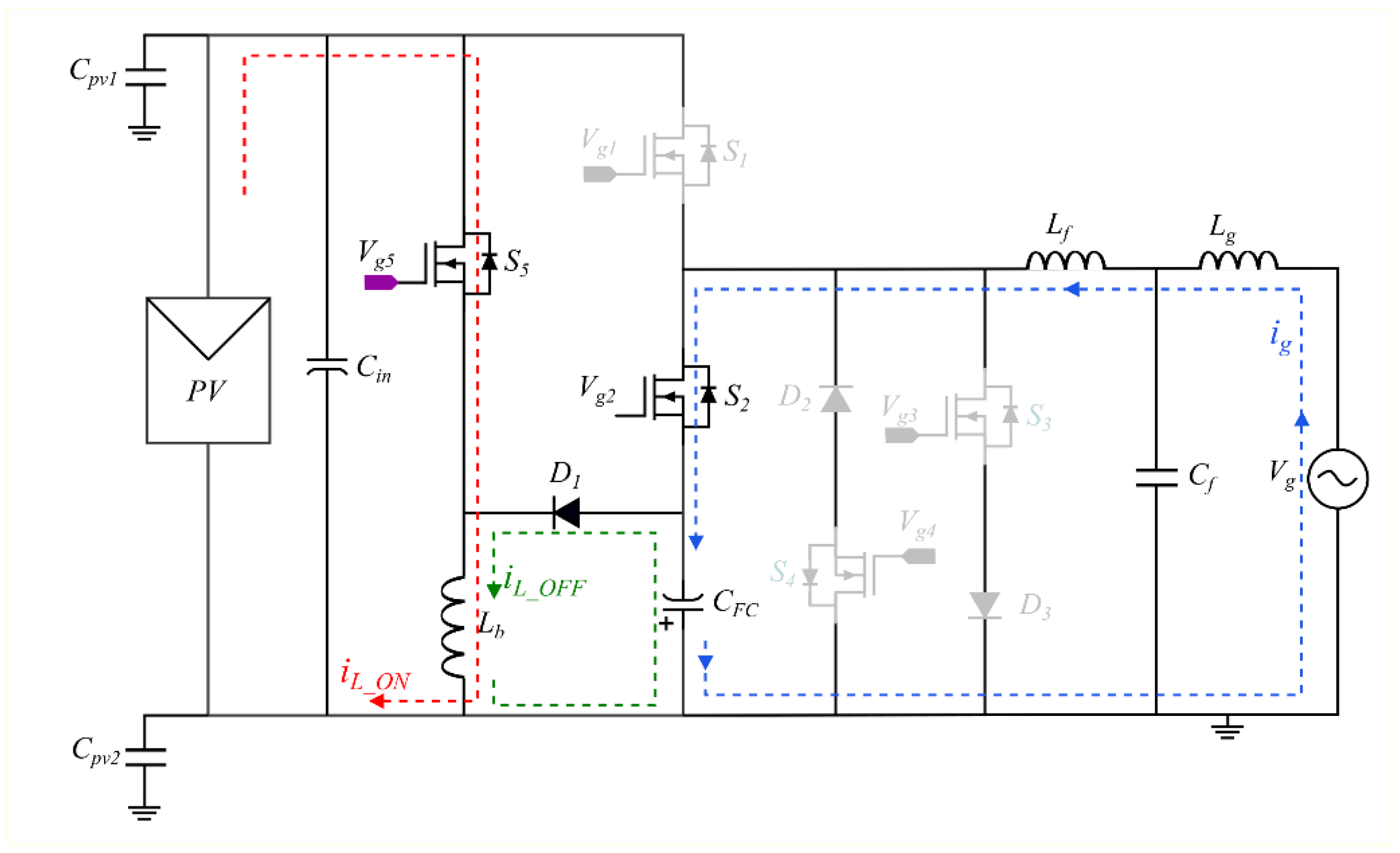
Figure 10 shows the proposed inverter configuration during this mode of operation. The flying capacitor starts discharging and works as a voltage source to supply the required negative current to the grid by activating the switch S2 to the ON state. All other three switches of the inverter, S1, S3, and S4, are OFF. Hence, only one switch in the current path conducts. In this mode, +2Vdc voltage stress is experienced across S1, while S4 experiences the flying capacitor voltage +Vdc across it. A unique feature is presented in this mode which does not exist in similar topologies in the literature. During the active negative cycle, once the flying capacitor starts to discharge the buck–boost circuit compensates for that discharged energy simultaneously by charging the flying capacitor C F C to keep the required voltage level. As a result, this helps to minimize the flying capacitor size significantly. At the same time, it prevents current spikes and reduces the current stress experienced by the capacitor when it is discharged deeply then recharged.

3.4. Negative Cycle (Zero State)

The operation of this mode is shown in Figure 11. The circuit operates in a similar manner to the positive cycle (zero state). Thus, switch S3 is ON whilst S4 is OFF. Hence, S3 and D3 conduct the freewheeling current in this mode. Throughout this operating mode, both S1 and S2 experience +Vdc voltage stress. The buck–boost circuit continues to precharge the flying capacitor for the negative active mode whenever required.
The aforementioned four modes of operation show the active switches in each mode and they continue repeating after each other. They verify the ability of the proposed inverter to generate a unipolar output voltage, Van, which is thereafter filtered out by the LCL filter to obtain the pure sinusoidal voltage and current in the grid. In addition, it shows that during the active states only one switch carries the load current, which reduces the conduction losses. The buck–boost circuit operates throughout all modes, even in the negative cycle (active) mode, as illustrated previously. This exhibits one advantage of the proposed transformerless inverter topology by reducing the flying capacitor size, in addition to limiting the charging current due to the existence of the inductor L b in the charging path. Table 2 shows a comparative summary of the proposed topology alongside the similar inverters in [23] and [27].

4. Design Guidelines and Loss Analysis

Brief design guidelines and loss analysis are presented in this section to assist in the selection of the proposed transformerless inverter components and its thermal management by estimating heat losses.

4.1. Buck–Boost Components Selection

Brief guidelines to select the buck–boost circuit components are illustrated. Based on the average method analysis of the inductor in steady state, the value of the inductor can be obtained as
L = V L Δ T Δ I = V o n D T Δ I = V o n   D Δ I   f  
where V o n   is the voltage across the inductor in the ON state, D the duty cycle which can be calculated by Equation (3), Δ I the current ripple, and f the switching frequency. Defining a ripple ratio factor r with an optimum value of 0.4 achieves a trade-off between inductor size and output capacitor current stress [29].
Δ I = r I L
where I L is the average current of the buck–boost inductor and I o is the output current. Substituting (5) into (4), the value of the inductor will be
L = V o n   D r   I L   f
The buck–boost diode average current and switch RMS current are addressed in Equations (7) and (8), respectively, while the voltage blocking capability must be at least rated as 2Vdc for both devices
I D = I o
I s w _ r m s = I L   D ( 1 + r 2 12 )
The flying capacitor (output capacitor of the buck–boost) is sized here based on the rated RMS current, because the voltage ripple requirement is not critical in this application; therefore
I c o u t _ r m s = I o   D + ( r 2 12 ) 1 D
where I c o u t _ r m s   is the conventional buck–boost output capacitor RMS current. Since the flying capacitor is discharged only in the negative half cycle in the proposed inverter, the RMS current of the flying capacitor I C F C _ r m s can be averaged to
I C F C _ r m s I c o u t _ r m s 2

4.2. Inverter Compoenents Selection

Based on the power switch voltage stresses mentioned in Section 3, the discrete devices of the inverter, S1 and S2, must be rated to withstand at least +2Vdc, while S3 and S4 must be rated for +Vdc voltage. Neglecting the phase shift caused by the output filter inductor, the duty cycle d ( t ) and grid current i g ( t ) can be described as follows [6]
d ( t ) = D m sin ( ω t )
i g ( t ) = I m sin ( ω t )
where D m is the maximum duty cycle, I m is the amplitude of the output current, denotes the average value over the grid switching period T g , and ω is the grid angular frequency. Accordingly, the current stresses of the power switches can be averaged over the grid switching cycle as
i S 1 ( t ) = d ( t ) i g ( t ) ,   from   0   t o   T g 2
i S 2 ( t ) = d ( t ) i g ( t ) ,   from   T g 2   t o   T g
i S 3 ( t ) = d ( t ) z e r o i g ( t ) ,   from   T g 2   t o   T g
i S 4 ( t ) = d ( t ) z e r o i g ( t ) ,   from   0   t o   T g 2
The duty cycle during the zero state denoted by d ( t ) z e r o is complementary to d ( t )
d ( t ) z e r o = 1 d ( t ) = 1 D m sin ( ω t )
The input capacitor of the DC bus can be sized based on the method suggested in [30] as
C i n = P 2 ω   V d c   Δ V
Note that   V d c   is the DC bus voltage, P the power of the inverter, and Δ V is the maximum permissible voltage ripple. The final part of the proposed topology is the LCL stage filter, which can be designed based on the analytical method suggested in [31]
L f =   V d c   8   f s w   r i p p l e %   I m
C f = x   P   ω   V o _ r m s 2
where L f is the filter inductor in the inverter side, f s w is the switching frequency, r i p p l e % the inductor current ripple ratio required, x is the reactive power percentage absorbed by the filter capacitor, the typical value of which is 0.05, and V o _ r m s is the RMS output voltage of the inverter. Then, the grid side inductor L g can be designed based on the methodologies recommended in [31,32,33], to limit the inverter output current harmonics according to IEEE 519-1992 and ensure system stability.
r a t t = | 1 I a t t 1 1 L f ( 2 π f s w ) 2 C f x   |
L g = r a t t L f
where I a t t is the attenuation factor to achieve the required LCL resonance and r a t t is the ripple attenuation.

4.3. Power Loss Analysis

The efficiency of the transformer is generally assessed using weighted efficiency, using measures such as CEC efficiency or EU efficiency. Therefore, the power loss in the power semiconductors of the proposed inverter is addressed in this part. Losses can be classified into conduction and switching losses. The average conduction power P c o n can be expressed as the voltage drop across the device multiplied by the passing current over the switching period. A comprehensive power loss analysis was carried out in [34,35]. It is recommended to use MOSFETs in the proposed inverter, and so
V o n _ m o s = i ( t )   R d s = i g ( t )   R d s
where V o n _ m o s is the voltage drop in the MOSFET during conduction, i ( t ) is the current passing through the MOSFET, and R d s is the MOSFET resistance. Hence, the power conduction losses are
P c o n _ S 1 = 1 T g 0 T g 2 | V o n _ m o s 1   i S 1 ( t ) | d t
where i S 1 ( t ) is the current in S1 during conduction and P c o n _ S 1 is the average power conduction loss in S1; since i S 1 ( t ) is almost unchanged in a switching cycle, the switching cycle averaging method can be utilized, and thus by substituting i S 1 ( t ) , this yields
P c o n _ S 1 = 1 T g 0 T g 2 | V o n _ m o s 1   i S 1 ( t ) | d t
Substituting (12) into (13), then (13) and (23) into Equation (25), we obtain
P c o n _ S 1 = 1 T g 0 T g 2 | D m I m 2 R d s sin 3 ( ω t ) | d ω t
Solving (26) and substituting T g = 2 π yields
P c o n _ S 1 = 2 D m I m 2 R d s 3 π
A similar analysis was carried out for the power switches S2, S3, and S4, which yields (28), (29), and (30), respectively, as follows
P c o n _ S 2 = 1 T g T g 2 T g | V o n _ m o s 2   i S 2 ( t )   d ( t ) | d t = 2 D m I m 2 R d s 3 π
P c o n _ S 3 = 1 T g T g 2 T g | V o n _ m o s 3   i S 3 ( t )   d ( t ) z e r o | d t = I m 2 R d s { 1 4 2 D m 3 π }
P c o n _ S 4 = 1 T g 0 T g 2 | V o n _ m o s 4   i S 4 ( t )   d ( t ) z e r o | d t = I m 2 R d s { 1 4 2 D m 3 π }
Furthermore, in the freewheeling period, the current passed through the diodes D2 in the positive cycle and D3 in the negative cycle, and the conduction loss of the diode can be obtained as
V o n _ d i o d e = V f + i ( t )   R d
P c o n _ d = 1 T g 0 T g 2 | V o n _ d i o d e   i ( t )   d ( t ) z e r o | d t
where V o n _ d i o d e is the diode voltage drop during conduction, V f is the diode forward voltage, R d is the diode resistance, i ( t ) the current through the device, and P c o n _ d the average diode conduction power loss. Substituting (31) into (32) yields Equation (33), and solving for T g = 2 π and i ( t ) = i g ( t ) results in (34) as follows
P c o n _ d = 1 T g 0 T g 2 | ( V f + i ( t )   R d )   i ( t )   d ( t ) z e r o | d t
P c o n _ d = V f   I m 2 π { 2 π D m 2 } + I m 2 R d 2 π { π 2 4 D m 3 }
The other losses experienced by the devices are the switching losses caused by the MOSFET’s transition states and the reverse recovery of the antiparallel body diodes. However, here, the MOSFET’s switching losses are considered while the reverse recovery diode loss is ignored by assuming SiC MOSFETs are used, which have a very fast recovery time. Therefore, the average switching losses can be estimated as follows
P o n = ( E o n V t e s t   I t e s t )   ( I m   V d c 2 π )   f s w
P o f f = ( E o f f V t e s t   I t e s t )   ( I m   V d c 2 π )   f s w
where P o n and P o f f are the ON average switching losses and OFF average switching losses, respectively, and E o n and E o f f are the ON and OFF energy losses, respectively, which were measured under specific conditions with V t e s t and I t e s t . These values can be obtained from the device datasheet. f s w is the switching frequency, I m the current amplitude, and V d c the bus voltage. Accordingly, the losses in the buck–boost circuit can be estimated as
P b _ c o n _ d = I o   V f
P c o n _ S 5 = I s w _ r m s 2   R d s
P s w _ S 5 = ( E o n + E o f f ) ( I m _ S 5   2 V d c V t e s t   I t e s t ) f s w
where P b _ c o n _ d is the buck–boost diode conduction loss, I m _ S 5 is the current amplitude through switch S5, and P c o n _ S 5 and P s w _ S 5 are the S5 conduction and switching losses, respectively. For simplicity, the worst-case losses are calculated in Equations (37)–(39), assuming a conventional buck–boost converter which needs to supply the load at all times, although in the proposed inverter it needs to supply the load during the negative half cycle only; thus, the definite losses are less than the calculated.

5. Simulation Results and Discussion

PSIM software was used to simulate the proposed inverter and evaluate its performance. The parameters used in the simulation are shown in Table 3.
As can be seen in Figure 12, the stresses on the switches are in accordance with the theoretical stresses mentioned in Section 3, where the maximum drain to source voltage across switches S1 and S2 equals +2Vdc, and across S3 and S4 equals +Vdc, whilst the buck–boost switch and diode voltage stresses equal +2Vds. Thus, switches S1, S2, S5, and D1 must be rated with the ability to withstand at least double the input voltage, and switches S3 and S4, as well as diodes D2 and D3, must be rated to withstand at least the input voltage.
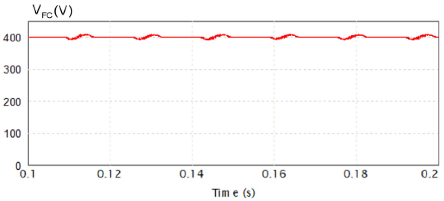
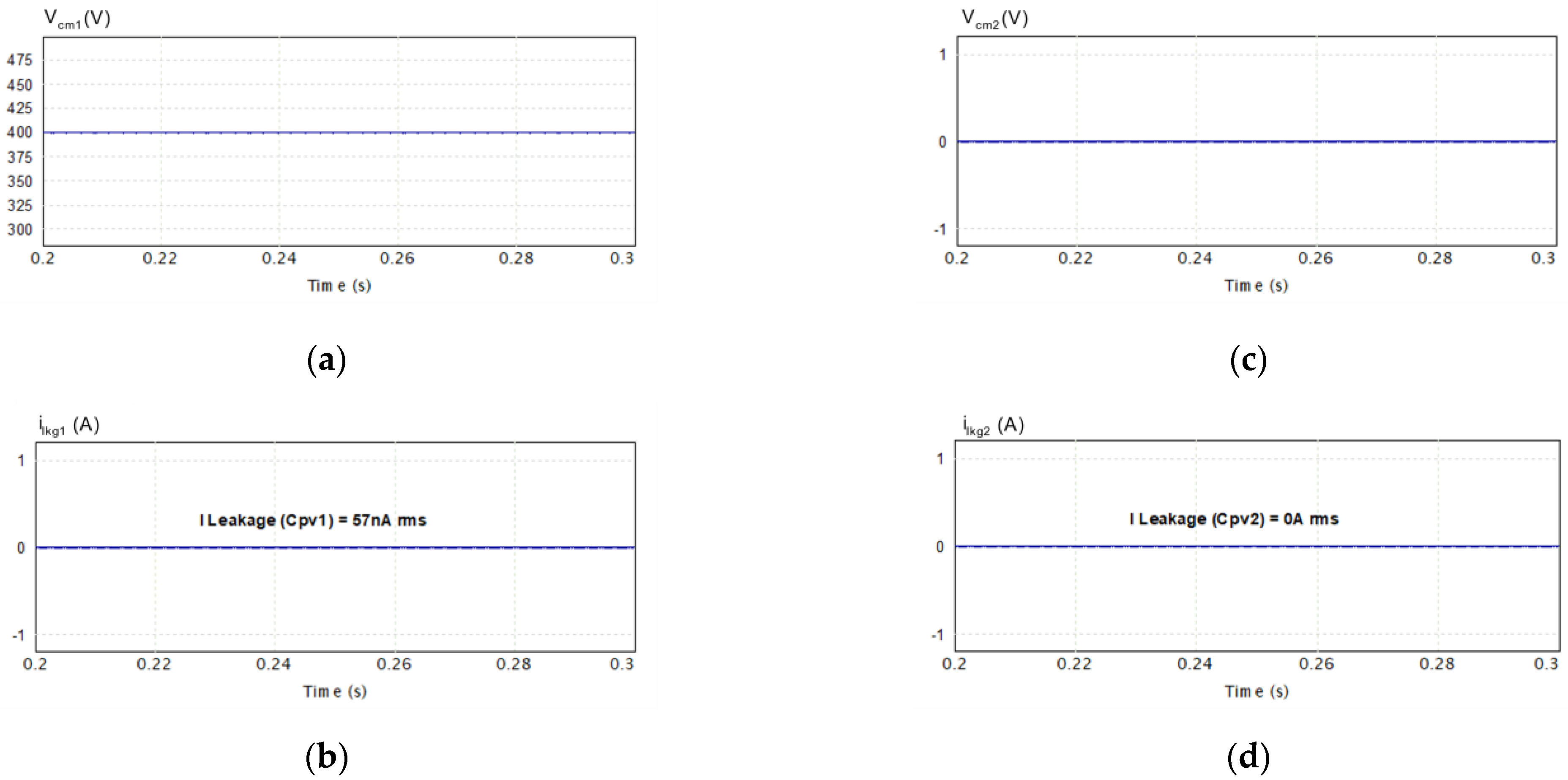
The flying capacitor voltage V F C waveform shown in Figure 13 represents a stable voltage during all periods of inverter power cycles. It presents the advantage of the buck–boost circuit in the proposed inverter topology, where it can charge the capacitor at all times irrespective of the inverter mode of operation. This leads to the minimization of the size of the flying capacitor (330 μF) as compared with similar inverters that utilize the flying capacitor concept, and it reduces the current spikes experienced by the other topologies that charge the flying capacitor directly without limiting the current, as achieved in the proposed topology by the buck–boost inductor. Another feature of this proposed inverter is shown in Figure 14: CMV is clamped to a constant value (400 V) across C P V 1 ; therefore, the leakage current is almost eliminated, and only a negligible current value of 57 nA rms is flowing in the circuit, as seen in Figure 14a,b. On the other hand, Figure 14c,d show the CMV and leakage current through the parasitic capacitance C P V 2 . It is noted that CMV is 0 V and the leakage current is eliminated completely.
The isolation is guaranteed by the high impedance of the parasitic capacitance between the PV panel’s body and the ground. Therefore, for the DC bus voltage supplied by the PV panels, there are only high-frequency voltage harmonics; thus, the parasitic capacitance impedance is very high, as shown in Equation (40).
X c p v = 1 j ω C P V
Regarding the voltage harmonics caused by switching the MOSFETs at high frequency, they are eliminated in the proposed topology by clamping the common mode voltage to a constant value, inputting DC bus voltage for CPV1 and the ground for CPV2. For this reason, there is almost no leakage current, as shown in Equation (1). Furthermore, the input voltage has no limitations as long as the selected switches and other components in the inverter can tolerate that voltage. Consequently, the proposed topology can be used at higher voltages, given that the semiconductors can tolerate that voltage and can comply with the standard norms in terms of leakage current requirements.
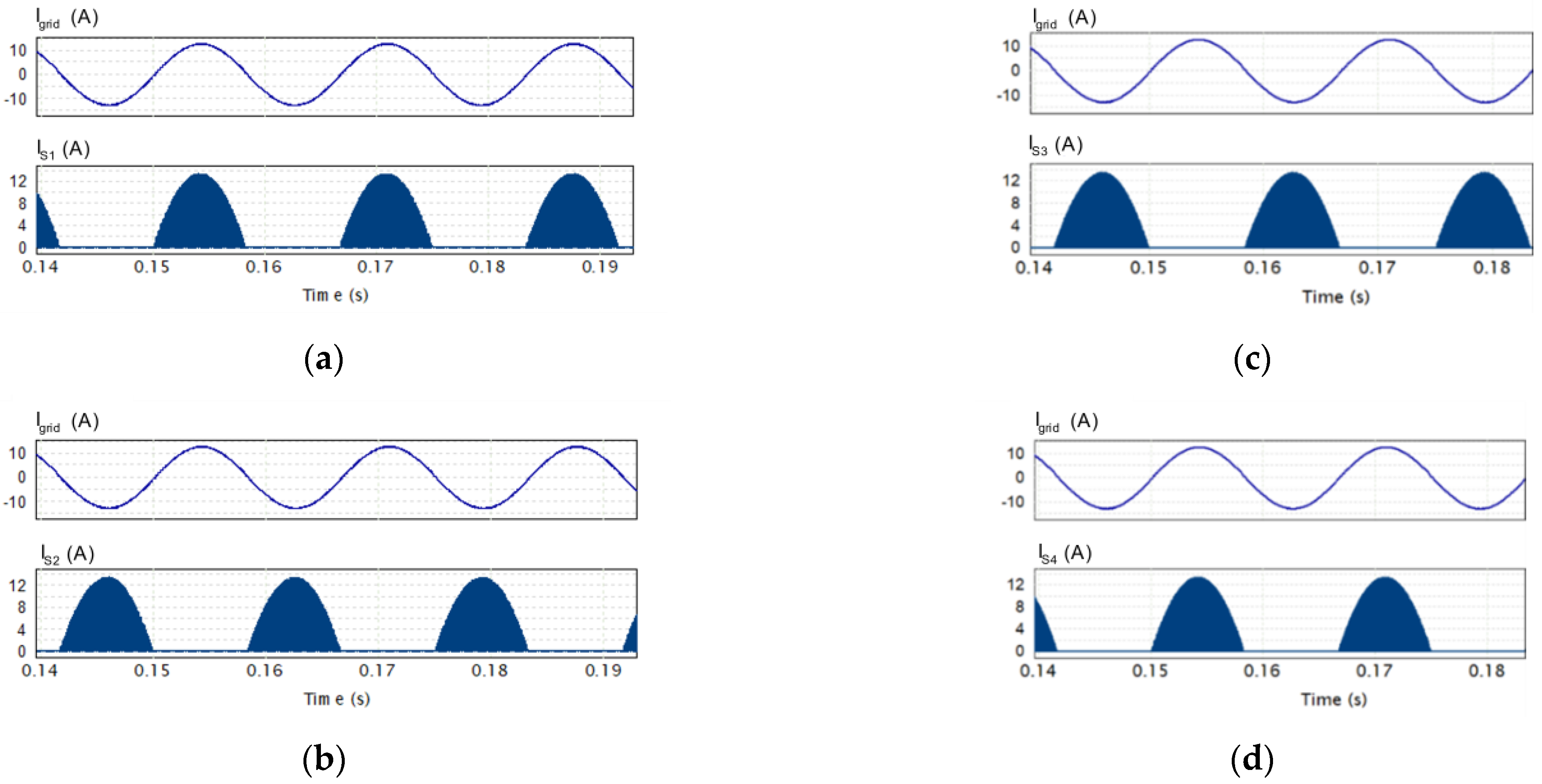
The current stresses represented in the simulated waveform of Figure 15 illustrate the current experienced by each semiconductor switch of the proposed transformerless inverter during the positive and negative power cycles, in addition to the freewheeling period (zero voltage state). Figure 15a shows that S1 carries the current injected to the grid Ig during the positive cycle (active), while S2 carries Ig in the negative cycle (active), as can be seen in Figure 15b. Additionally, Figure 15c,d exhibit the simulation waveforms of the currents carried by S3 and S4 during the positive and negative freewheeling cycles to permit output inductor current freewheeling and achieve the zero voltage state for unipolar SPWM.
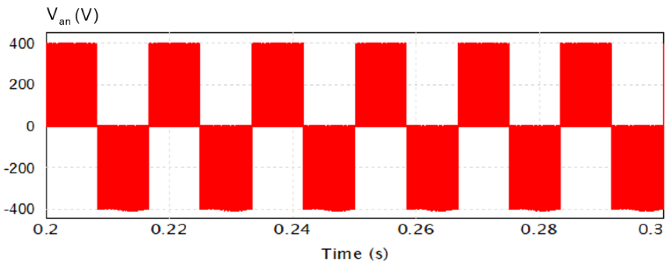
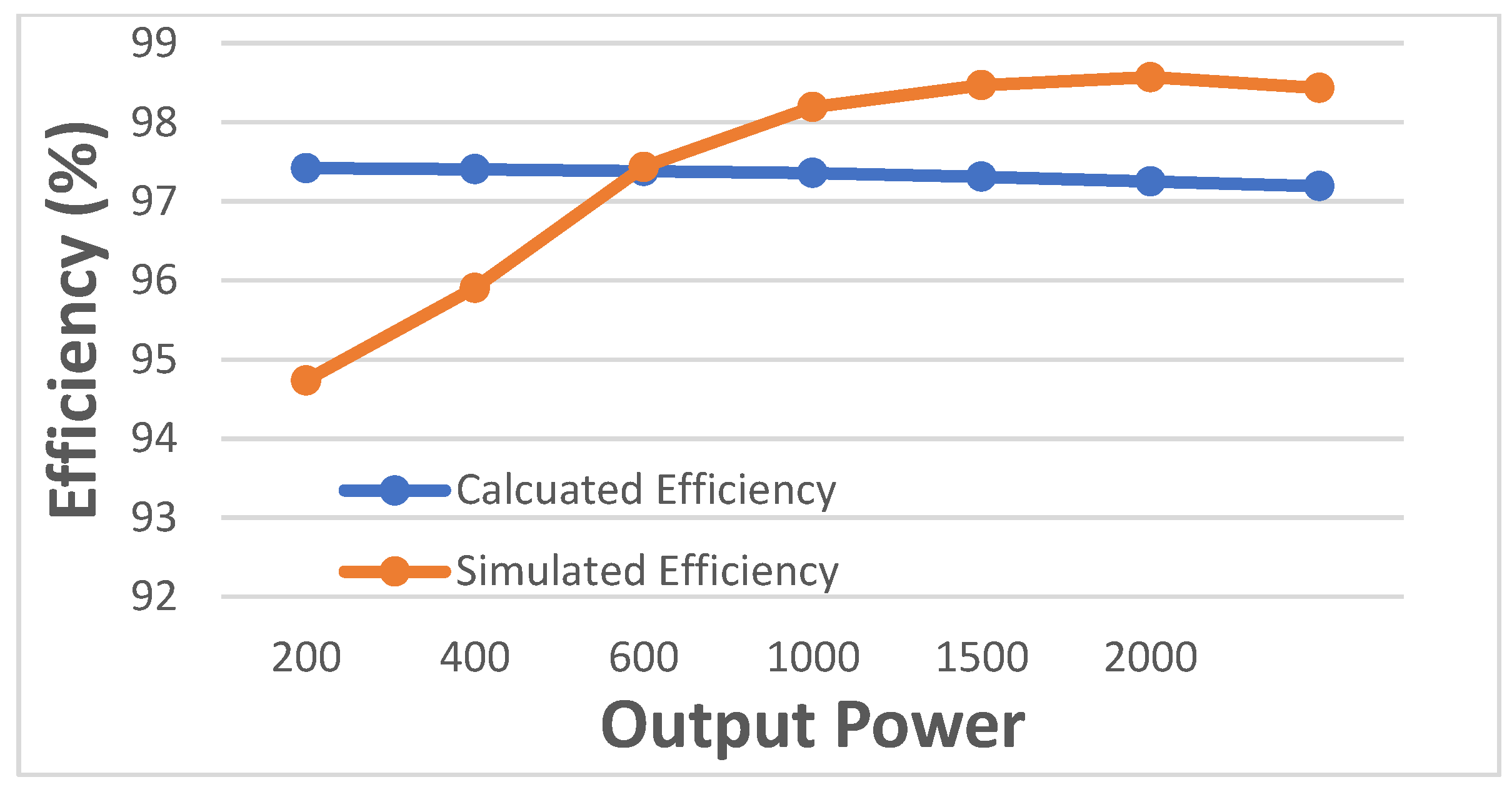
As illustrated in Figure 16, the unipolar SPWM modulation technique is achieved. The simulated waveform Van presents +Vdc and 0 V in the positive power cycle and −Vdc and 0 V during the negative power cycle. Hence, the three states required to implement the unipolar SPWM are conducted at +Vdc, −Vdc, and zero voltage. Therefore, the proposed inverter generates a unipolar output voltage, which reduces the current ripple and filter inductor losses. Hence, smaller filter inductors are required as compared to other topologies with the bipolar SPWM modulation technique. The grid voltage and currents of the simulated proposed inverter topology are illustrated in Figure 17. A sinusoidal voltage waveform with very low distortion is presented in the grid side Vg. The simulated waveforms show a unity power factor, whereby the currents are in phase with the grid voltage. Figure 17a shows the grid voltage Vg with the inverter side current Iinv before the LCL output filter. As shown in Figure 17a, it contains some distortion, while Figure 17b shows Vg with the injected grid current Ig after the LCL, where the effect of the LCL filter is shown clearly in smoothening the grid current Ig. The performance of the proposed transformerless inverter is evaluated in terms of the efficiency using the power loss calculations mentioned in Section 4 and compared with the simulated results obtained using the PSIM thermal module. There is a slight difference between the simulation and theoretical results, as shown in Figure 18. This is mainly due to the approximation made in simplifying the power loss equations of the buck–boost circuit, as explained previously.
The weighted efficiency was calculated according to California Energy Commission (CEC). The value was found to be 97.29% and 98.33% for the calculated and simulated efficiency, respectively. The CEC equation is given by
η C E C = 0.04 η 10 % + 0.05 η 20 % + 0.12 η 30 % + 0.21 η 50 % + 0.53 η 75 % + 0.05 η 100 %
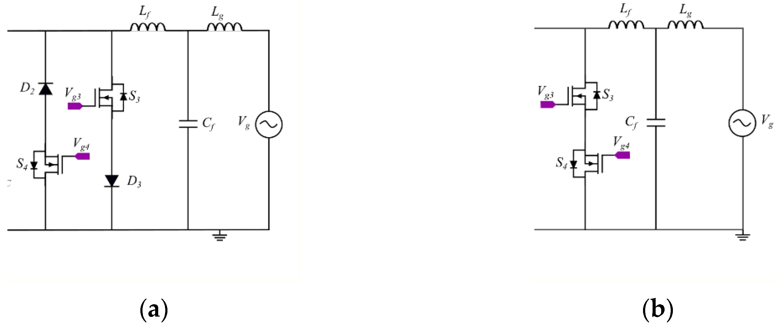
There are two circuit configurations that can be implemented in the freewheeling path of the inverter, either using two branches consisting of two MOSFETs with external diodes, as suggested in the proposed topology, or using one branch consisting of two MOSFETs and utilizing the internal antiparallel diodes. Each circuit has its own pros and cons. Both configurations are shown in Figure 19.
The circuit shown in Figure 19a was chosen in the proposed topology over the circuit in Figure 19b, because it would increase the efficiency of the inverter. The antiparallel diodes in the MOSFETs, in particular, SiC, have much higher forward voltage compared with external SiC diodes, which have low forward voltage. Consequently, the efficiency of the system is increased when using external diodes at the expense of adding more devices and increasing the cost. Figure 20 shows the efficiency of the proposed inverter if using a one-branch circuit, as shown in Figure 19b.
The weighted efficiency was determined according to CEC. It was found to be 96.76% and 97.8% for the calculated and simulated efficiency, respectively. This is less efficient compared with the efficiency of the proposed circuit, as can be seen in Figure 18.

6. Conclusions

In this paper, a flying capacitor buck–boost transformerless inverter was proposed for single-phase grid-connected PV systems. The proposed topology differs from the similar types in the literature by its ability to charge the flying capacitor continuously, even in the negative power cycle (active). Thus, it can minimize the size of the flying capacitor and prevents an inrush current when charging the flying capacitor due to the existence of the inductor in the buck–boost circuit. The performance of the proposed inverter was verified using a PSIM simulation, which showed that the results are consistent with the theoretical analysis that was carried out. In general, the proposed transformerless inverter eliminates the leakage current, reduces the losses, and reduces the flying capacitor size and filtration requirement due to unipolar SPWM modulation. The efficiency of the proposed inverter was evaluated at 2 kW rated power using theoretical calculations and simulation results, and showed a CEC efficiency of 97.29% and 98.33%, respectively. However, it may suffer buck–boost circuit losses at powers greater than 2 kW; in particular, the switching losses. SiC devices were used in the evaluation of the proposed inverter and they are recommended to be used in their design, because of their lower switching losses at higher frequency which contribute to reduce the size of passive components. Moreover, for further efficiency enhancement, external SiC diodes were used instead of the MOSFETs antiparallel body diodes in the freewheeling path.

Author Contributions

Conceptualization, A.S.; Methodology, A.S. and K.S.; Software, A.S.; Validation, K.S.; Formal analysis, A.S.; Resources, A.S.; Writing—Original draft preparation, A.S.; Writing—Review and editing, A.S. and K.S.; Supervision, K.S.; Funding acquisition, K.S. All authors have read and agreed to the published version of the manuscript.

Funding

This project was funded by the Deanship of Scientific Research (DSR) at King Abdulaziz University, Jeddah, under grant no. RG-60-135-42.

Acknowledgments

The authors, therefore, acknowledge with thanks Deanship of Scientific Research (DSR) for technical, administrative, and financial support.

Conflicts of Interest

The authors declare no conflict of interest.

References

  1. Ahshan, R. Potential and Economic Analysis of Solar-to-Hydrogen Production in the Sultanate of Oman. Sustainability 2021, 13, 9516. [Google Scholar] [CrossRef]
  2. Wirth, D.H.; Ise, F. Recent Facts about Photovoltaics in Germany; Fraunhofer Institute for Solar Energy Systems ISE: Fraunhofer, Germany, 2015. [Google Scholar]
  3. Poulek, V.; Libra, M. Distribution Grid Stability—Influence of Inertia Moment of Synchronous Machines. Appl. Sci. 2020, 10, 9075. [Google Scholar]
  4. International Renewable Energy Agency. REthinking Energy 2017: Accelerating the Global Energy Transformation; International Renewable Energy Agency (IRENA): Abu Dhabi, United Arab Emirates, 2017; ISBN 978-92-95111-05-9. [Google Scholar]
  5. Khan, M.N.H.; Forouzesh, M.; Siwakoti, Y.P.; Li, L.; Kerekes, T.; Blaabjerg, F. Transformerless Inverter Topologies for Single-Phase Photovoltaic Systems: A Comparative Review. IEEE J. Emerg. Sel. Top. Power Electron. 2020, 8, 805–835. [Google Scholar] [CrossRef]
  6. Gu, Y.; Li, W.; Zhao, Y.; Yang, B.; Li, C.; He, X. Transformerless Inverter With Virtual DC Bus Concept for Cost-Effective Grid-Connected PV Power Systems. IEEE Trans. Power Electron. 2013, 28, 793–805. [Google Scholar] [CrossRef]
  7. Albalawi, H.; Zaid, S.A. An H5 Transformerless Inverter for Grid Connected PV Systems with Improved Utilization Factor and a Simple Maximum Power Point Algorithm. Energies 2018, 11, 2912. [Google Scholar] [CrossRef] [Green Version]
  8. Renewable Energy Devices and Systems with Simulations in MATLAB® and ANSYS®, 1st ed.; Blaabjerg, F.; Ionel, D.M. (Eds.) CRC Press: Boca Raton, FL, USA, 2017; ISBN 978-1-4987-6582-4. [Google Scholar]
  9. Xiao, H.; Xie, S. Leakage Current Analytical Model and Application in Single-Phase Transformerless Photovoltaic Grid-Connected Inverter. IEEE Trans. Electromagn. Compat. 2010, 52, 902–913. [Google Scholar] [CrossRef]
  10. Estévez-Bén, A.A.; Alvarez-Diazcomas, A.; Macias-Bobadilla, G.; Rodríguez-Reséndiz, J. Leakage Current Reduction in Single-Phase Grid-Connected Inverters—A Review. Appl. Sci. 2020, 10, 2384. [Google Scholar] [CrossRef] [Green Version]
  11. Liu, W.; Yang, Y.; Kerekes, T.; Liivik, E.; Vinnikov, D.; Blaabjerg, F. Common-Mode Voltage Analysis and Reduction for the Quasi-Z-Source Inverter with a Split Inductor. Appl. Sci. 2020, 10, 8713. [Google Scholar] [CrossRef]
  12. Li, W.; Gu, Y.; Luo, H.; Cui, W.; He, X.; Xia, C. Topology Review and Derivation Methodology of Single-Phase Transformerless Photovoltaic Inverters for Leakage Current Suppression. IEEE Trans. Ind. Electron. 2015, 62, 4537–4551. [Google Scholar] [CrossRef]
  13. Figueredo, R.S.; de Carvalho, K.C.M.; Ama, N.R.N.; Matakas, L. Leakage Current Minimization Techniques for Single-Phase Transformerless Grid-Connected PV Inverters—An Overview. In Proceedings of the 2013 Brazilian Power Electronics Conference, Gramado, Brazil, 27–31 October 2013; pp. 517–524. [Google Scholar]
  14. Almasoudi, F. Design and Evaluation of High Efficiency Power Converters Using Wide-Bandgap Devices for PV Systems. Master’s Thesis, University of Denver, Denver, CO, USA, 2018. [Google Scholar]
  15. Zeb, K.; Khan, I.; Uddin, W.; Khan, M.A.; Sathishkumar, P.; Busarello, T.D.C.; Ahmad, I.; Kim, H.J. A Review on Recent Advances and Future Trends of Transformerless Inverter Structures for Single-Phase Grid-Connected Photovoltaic Systems. Energies 2018, 11, 1968. [Google Scholar] [CrossRef] [Green Version]
  16. Tofigh Azary, M.; Sabahi, M.; Babaei, E.; Abbasi Aghdam Meinagh, F. Modified Single-Phase Single-Stage Grid-Tied Flying Inductor Inverter With MPPT and Suppressed Leakage Current. IEEE Trans. Ind. Electron. 2018, 65, 221–231. [Google Scholar] [CrossRef]
  17. Jiao, Y.; Lee, F.C. New Modulation Scheme for Three-Level Active Neutral-Point-Clamped Converter With Loss and Stress Reduction. IEEE Trans. Ind. Electron. 2015, 62, 5468–5479. [Google Scholar] [CrossRef]
  18. Ahmad, Z.; Singh, S.N. Comparative Analysis of Single Phase Transformerless Inverter Topologies for Grid Connected PV System. Sol. Energy 2017, 149, 245–271. [Google Scholar] [CrossRef]
  19. Dzung, P.Q.; Dat, D.N.; Anh, N.B.; Hiep, L.C.; Lee, H.-H. Design of HERIC Inverter for PV Systems by Using Hardware in the Loop (HIL) Concept. In Proceedings of the 2014 9th IEEE Conference on Industrial Electronics and Applications, Hangzhou, China, 9–11 June 2014; pp. 2035–2040. [Google Scholar]
  20. Almasoudi, F.; Matin, M. An Improved Proposed Single Phase Transformerless Inverter with Leakage Current Elimination and Reactive Power Capability for PV Systems Application. J. Low Power Electron. Appl. 2018, 8, 29. [Google Scholar] [CrossRef] [Green Version]
  21. Karschny, D. Flying Inductor Topology. German Patent DE19642522C1, 15 October 1998. [Google Scholar]
  22. Ardashir, J.F.; Siwakoti, Y.P.; Sabahi, M.; Hosseini, S.H.; Blaabjerg, F. S4 Grid-Connected Single-Phase Transformerless Inverter for PV Application. In Proceedings of the IECON 2016—42nd Annual Conference of the IEEE Industrial Electronics Society, Florence, Italy, 24–27 October 2016; pp. 2384–2389. [Google Scholar]
  23. Siwakoti, Y.P.; Blaabjerg, F. Common-Ground-Type Transformerless Inverters for Single-Phase Solar Photovoltaic Systems. IEEE Trans. Ind. Electron. 2018, 65, 2100–2111. [Google Scholar] [CrossRef]
  24. Maniktala, S. The Principles of Switching Power Conversion. In Switching Power Supplies A–Z, 2nd ed.; Newnes: Amsterdam, The Netherlands, 2012; pp. 39–41. ISBN 978-0-12-386533-5. [Google Scholar]
  25. Erickson, R.W.; Maksimović, D. Principles of Steady-State Converter Analysis. In Fundamentals of Power Electronics; Springer: Gewerbestrasse, Switzerland, 2020; pp. 15–30. ISBN 978-3-030-43879-1. [Google Scholar]
  26. Ballo, A.; Grasso, A.D.; Palumbo, G. A Review of Charge Pump Topologies for the Power Management of IoT Nodes. Electronics 2019, 8, 480. [Google Scholar] [CrossRef] [Green Version]
  27. Siwakoti, Y.P.; Blaabjerg, F. A Novel Flying Capacitor Transformerless Inverter for Single-Phase Grid Connected Solar Photovoltaic System. In Proceedings of the 2016 IEEE 7th International Symposium on Power Electronics for Distributed Generation Systems (PEDG), Vancouver, BC, Canada, 27–30 June 2016; pp. 1–6. [Google Scholar]
  28. Behera, P.K.; Das, S.; Pattnaik, M. Performance Comparison Between Bipolar and Unipolar Switching Scheme for a Single-Phase Inverter Based Stand-Alone Photovoltaic System. In Proceedings of the 2019 IEEE 16th India Council International Conference (INDICON), Rajkot, Gujarat, 13–15 December 2019; pp. 1–4. [Google Scholar]
  29. Maniktala, S. DC-DC Converter Design and Magnetics. In Switching Power Supplies A–Z; Newnes: Amsterdam, The Netherlands, 2012; pp. 72–76. ISBN 978-0-12-386533-5. [Google Scholar]
  30. Memon, M. Sizing of Dc-Link Capacitor for a Grid Connected Solar Photovoltaic Inverter. Indian J. Sci. Technol. 2020, 13, 2272–2281. [Google Scholar] [CrossRef]
  31. 10-KW Bidirectional Three-Phase Three-Level (T-Type) Inverter and PFC Reference Design; Application Note TIDA-01606; Texas Instruments: Dallas, TX, USA, 2018.
  32. Busarello, T.D.C. LCL Filter Design Procedure. IEEE Dataport. 2019. Available online: https://ieee-dataport.org/documents/lcl-filter-design-procedure (accessed on 8 May 2021).
  33. Liu, H. Control Design of a Single-Phase DC/AC Inverter for PV Applications. Master’s Thesis, University of Arkansas, Fayetteville, AR, USA, 2016. Available online: http://scholarworks.uark.edu/etd/1618 (accessed on 9 May 2021).
  34. Barater, D.; Concari, C.; Buticchi, G.; Gurpinar, E.; De, D.; Castellazzi, A. Performance Evaluation of a Three-Level ANPC Photovoltaic Grid-Connected Inverter With 650-V SiC Devices and Optimized PWM. IEEE Trans. Ind. Appl. 2016, 52, 2475–2485. [Google Scholar] [CrossRef] [Green Version]
  35. Geetha, K.; Sreenivasappa, B.V. Power Loss Calculation for IGBT and SiC MOSFET. 2020. Available online: https://www.researchgate.net/publication/343976798_POWER_LOSS_CALCULATION_FOR_IGBT_and_SiC_MOSFET (accessed on 6 May 2021).
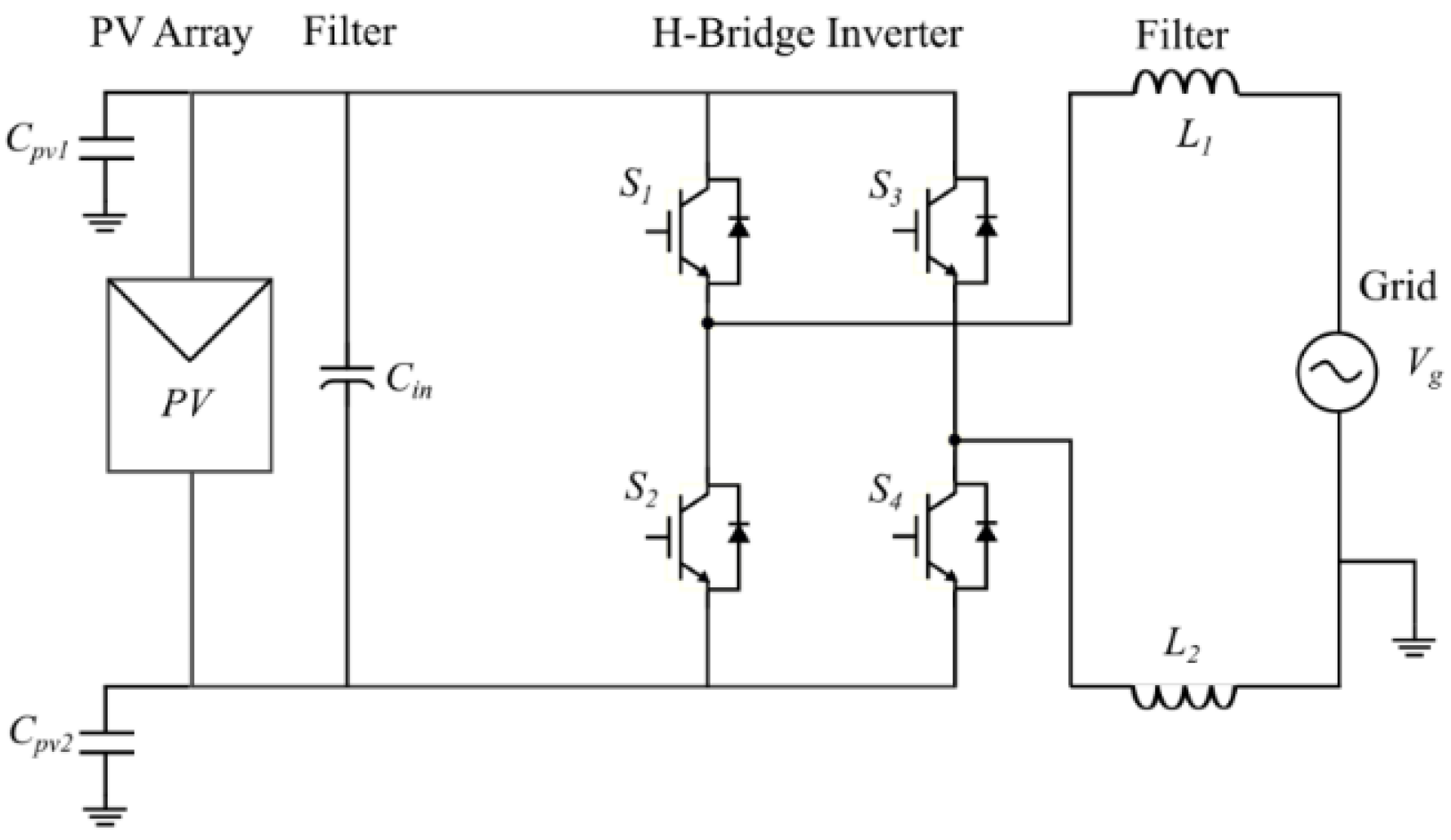
Figure 1. Full Bridge (FB or H-Bridge) structure of a transformerless inverter.
Applsci 11 10841 g001
Figure 2. Common mode circuit.
Applsci 11 10841 g002
Figure 3. Proposed transformerless single-phase grid-tied inverter.
Applsci 11 10841 g003
Figure 4. Buck–boost circuit and its operation: (a) buck–boost basic structure; (b) ON state circuit; (c) OFF state circuit.
Applsci 11 10841 g004
Figure 5. Illustration of flying capacitor operation.
Applsci 11 10841 g005
Figure 6. The proposed flying capacitor circuit.
Applsci 11 10841 g006
Figure 7. The proposed transformerless inverter topology and its modulation technique: (a) the proposed transformerless inverter; (b) unipolar SPWM modulation signal.
Applsci 11 10841 g007
Figure 8. Positive power cycle (active) operating mode of the proposed transformerless inverter.
Applsci 11 10841 g008
Figure 9. Positive power cycle (zero state) operating mode of the proposed transformerless inverter.
Applsci 11 10841 g009
Figure 10. Negative power cycle (active) operating mode of the proposed transformerless inverter.
Applsci 11 10841 g010
Figure 11. Negative power cycle (zero state) operating mode of the proposed transformerless inverter.
Applsci 11 10841 g011
Figure 12. The simulation results of the voltage stresses on the switches: (a) S1; (b) S2; (c) S3; (d) S4; (e) S5.
Applsci 11 10841 g012
Figure 13. Waveform of the flying capacitor voltage C F C .
Applsci 11 10841 g013
Figure 14. Common mode voltages and leakage currents across the parasitic capacitances of the PV array: (a) CMV across C P V 1 ; (b) leakage current in C P V 1 ; (c) CMV across C P V 2 ; (d) leakage current in C P V 2 .
Applsci 11 10841 g014
Figure 15. Current stresses in the semiconductor switches compared with grid current Ig: (a) S1; (b) S2; (c) S3; (d) S4.
Applsci 11 10841 g015
Figure 16. Output voltage of the proposed inverter Van.
Applsci 11 10841 g016
Figure 17. Grid voltage and injected current before and after LCL filter: (a) simulated grid voltage Vg with inverter side current Iinv; (b) simulated grid voltage Vg alongside grid current Ig.
Applsci 11 10841 g017
Figure 18. The efficiency of the proposed transformerless inverter.
Applsci 11 10841 g018
Figure 19. Freewheeling path circuit configurations; (a) two branches including two MOSFETs with external diodes, as suggested in the proposed inverter; (b) one branch with two MOSFETs.
Applsci 11 10841 g019
Figure 20. The efficiency of the transformerless inverter using the freewheeling circuit in Figure 19b.
Applsci 11 10841 g020
Table 1. Leakage current with discontinuity time according to VDE 0126-1-1.
Leakage Current (mA)Fault Discontinuity Time (ms)
30300
60150
10040
Table 2. Comparative table between the proposed inverter and similar inverters.
Inverter Topology in [27]Inverter Topology in [23]The Proposed Inverter
Two switches in series carry the load current during the active states of the positive and negative power cycles.Only one switch carries the load current during the active states of the positive and negative power cycles.Only one switch carries the load current during the active states of the positive and negative power cycles.
It does not charge the flying capacitor during the active state of the negative power cycle.It does not charge the flying capacitor during active states.It charges the flying capacitor during all operating states.
No RB-IGBT required.It required two switches with bipolar voltage-blocking capability, such as RB-IGBT.No RB-IGBT required.
No proposed way to control or reduce the inrush current during the charging of the flying capacitorThe inrush current during the charging of the flying capacitor cannot be fully controlled; it ranges
from 2 Iac, max to 5 Iac, max
In the proposed inverter, the flying capacitor charging current can be controlled using the buck–boost inverter because the capacitor charges through the inductor. Based on the nature of the inductor, in that it tries to oppose the current change, the slope of the current can be controlled.
I m a x = I o   1 D   ( 1 + r 2 )
where I o is the output current of the buck–boost inverter, in this case I a c _ m a x , D the duty cycle, and r the ripple ratio. Hence, the maximum current can be controlled by inductor value because r = V o n   D L   I L f
Table 3. System design parameters used for the simulation.
ParametersValue
DC Bus Input Voltage V d c 400 Vdc
Grid Voltage V g 220 Vac
Grid Frequency f g 60 Hz
Switching Frequency f s w 60 kHz
PV Array Parasitic Capacitance ( C P V 1 , C P V 2 ) 80 nF
Rated Power2 kW
Output Current (peak) I g 12.86 A
Flying Capacitor C F C 330 µF
Buck–Boost Inductor L b 870 µH
Inverter Side Filter L f 860 µH
Grid Side Filter L g 280 µH
Filter Capacitor C f 4.7 µF
SwitchesC3M0021120K
DiodesC4D20120A
Publisher’s Note: MDPI stays neutral with regard to jurisdictional claims in published maps and institutional affiliations.