1. Introduction
Nowadays, at the international level [
1], statistics show that by the end of 2025, there will be over 20,000,000 operational drones/UAVs, with an estimated value of transactions in this field of over USD 45.8 billion. Within these types of UAVs, the ones with applications relating to social security represent over 60%; consequently, drones are expected to have a high market potential. The crisis of personnel working in agriculture as well as the development of many large farms that cover thousands of hectares are pushing farmers and agricultural associations to use UAVs with increased autonomy for surveillance and culture monitoring. The development of highly advanced video-cameras as well as artificial intelligence is also a factor that helps in the development of UAVs.
One of the most convenient methods to extend the autonomy of electrically propelled UAVs is to install photovoltaic cells on the wings and/or fuselage and to use the electrical power generated by these cells to charge the batteries. There have been numerous attempts to install photovoltaic cells on UAV wings [
2,
3,
4,
5]. The main issues that have been encountered in all of these attempts are generated by the efficiency and the reliability of the photovoltaic cells. The attempt to use large-sized photovoltaic cells was hindered by wing vibrations of the UAVs, which led to silica wafer cracking and sometimes the disruption of soldered connections. Moreover, due to the frequency at which UAVs manoeuvre, the solar irradiation is not equally dispersed on the cell surface, leading to a less efficient conversion. Another disrupting factor was that the weight of the solar cell matrix, the material used to connect them, and the resin used to glue them on the wings increased significantly the weight of the UAV, thus decreasing the weight of the usable payloads.
The approach presented here was completely different and was oriented in two main directions:
- -
To develop an ultra-light UAV wing;
- -
To develop photovoltaic cells that are suitable to be embedded into the structure of the wing.
These two efforts are interconnected by specific requirements such as the mechano-climatic loads that are specific for fixed wings.
The present paper is structured into two main parts: A part consisting of an introduction as well as discussion of the design and fabrication processes, and the second part presents the tests and the prototype validation, conclusions, and perspectives. A short video is also included in the
Supporting Materials that documents the flight of the prototype.
2. Design and Fabrication
In order to shorten the development process, the design of the ultra-light UAV wing was based on the aerodynamic shape developed for Hirus, an operational UAV from the industrial partner involved in this work. The initial wing structure of Hirus was based on glass fibre fabric embedded into an epoxy resin. In the original design, two composite layers of fibre glass fabric were placed over a layer of aerogel (Rohacell-Evonik Industries AG, Essen, Germany). To compensate for the PV and the addition weight of the wiring, instead of fibre glass fabric, which has a relatively high weight, it was decided that a new composite material based on carbon fibre (Vuhlets
®, Texpack
® S.r.l. Via Galileo Galilei, 24 25030 Adro (BS) Italy) with a lower weight (40 g/m
2) and higher resistance would be used. Thus, the initial mass of the wing, which was around 850 g when made of glass fibre, was decreased to 550 g, providing 300 g of additional weight for the photovoltaic cells and wires.
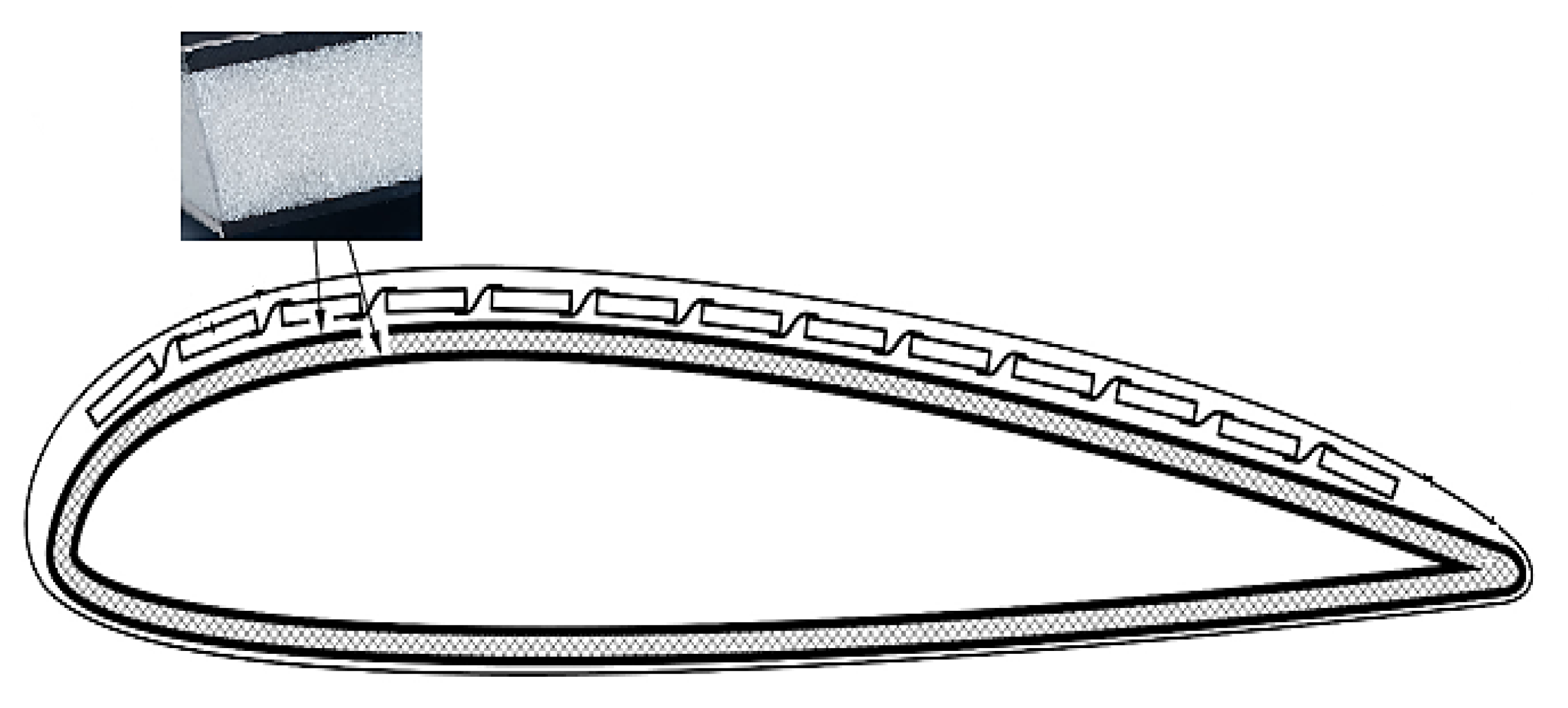
Figure 1 presents a schematic transversal section through the UAV’s wing, which presents a detailed sandwich structure: carbon fibre fabric, aerogel, carbon fibre fabric.
The next step was to establish the best dimensions and technology for photovoltaic cell fabrication. For this step a thorough calculation of efforts and wing bending was conducted.
A simplified evaluation of the deformations according to the pressure difference applied on the surface of the photovoltaic element (using average values at ambient temperature [
6]) was performed using the calculation theory used at bars on the two main directions of the photovoltaic element (length, width).
The following values were used to verify the determinations that were made and to estimate (coarsely) the maximum deformations of the wing on the two directions due to the pressure that was on it during the flight:
- -
L = 20 mm, length of the element;
- -
d = 10 mm, width of the element;
- -
g = 0.3 mm, element thickness;
- -
E = 160 GPa, silicon modulus of elasticity (for semiconductors) [
7].
The formula used for simulating the wing bending was [
1]
where:
- -
y(x) represents the deformation of the bar as a function of the position x along the bar;
- -
w represents the load evenly distributed along the bar;
- -
E is the mode of elasticity;
- -
I is the moment of inertia of the section;
- -
x is the position along the bar;
- -
and D is the length of the bar.
Figure 2 presents a graphic representation of the UAV’s wing deformation on the two axes.
As one can observe,
Figure 2 shows the progressive load simulated using the fixed-bar principle to be applied on the wing in order to establish the bending amplitude (on both sides L—length, and d—wide). It can be observed that the maximum deformation of the wing on the length (L) at a pressure of 1 atm lies below 0.6 mm. For a bar supported at the ends and that is uniformly loaded, the maximum deformation (maximum arrow) occurs at half the distance between the ends. (For a wing that is up to 1.5 m wide and with UAV speeds of up to 250 km/h, it was determined that the dimensions of the photovoltaic cells should be L = 20 mm, d = 10 mm.)
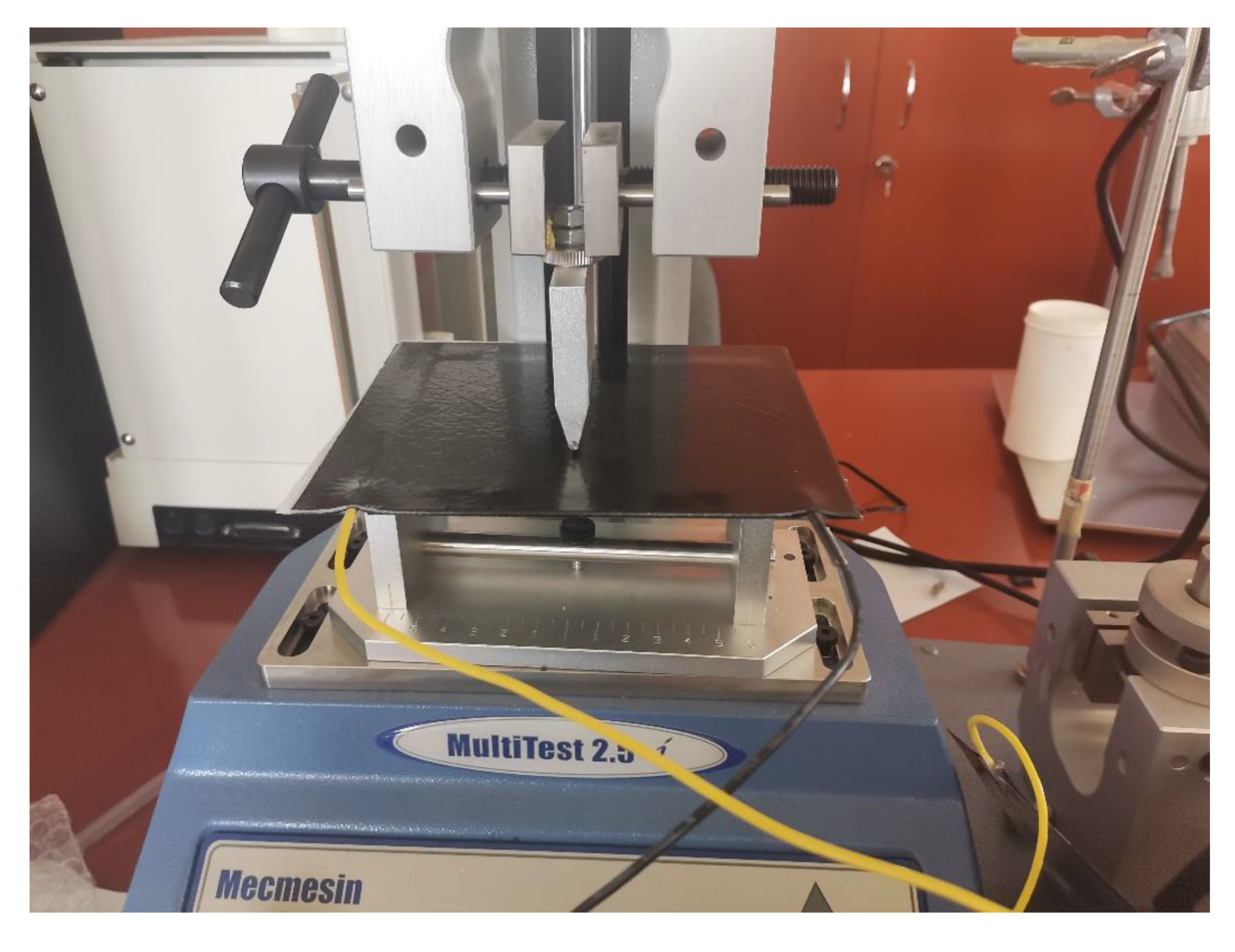
In order to verify the maximum allowable deformation of the photovoltaic cells, destructive tests were also performed using the MECMESIN MultiTest 2.5 Software-controlled force test system (Newton House, Spring Copse Business Park, Slinfold, West Susssex, United Kingdom), the results of which will be presented further on in
Section 3. Following the practical tests, a maximum deformation arrow of 0.8 mm was found to be acceptable in the “L” direction, which is part of the calculation of the maximum deformation of the wing.
The photovoltaic structures were made of silicon wafers with a diameter of 3 inches, an orientation <100>, type p, resistivity 1–3 Ω·cm, and a thickness of 350 µm. The size of the solar cell structures with a textured surface is 10 × 22 mm2 (the connexion ribbon/front pad/collector was extended from 1 mm to 2 mm in order to provide a larger connection surface). The texturing of the cell surfaces was conducted through a photolithographic process that defined inverse pyramids with sides of 10 µm that were placed in a network between the collection contacts/electrodes of the photocarriers generated by incident light.
By taking into consideration the wing profile as it is presented in
Figure 1 that presents a significant curvature, it was obvious that not all of the photovoltaic cells will have the same exposure to the incident Sun light. In order to overcome this disadvantage, it was decided to improve the design of the cells to obtain a much better exposure to the irradiation source. It was determined that the solution that would be used would be to texturize the surface of the cells and thus reduce reflection losses and increase absorption in the near IR spectral range [
8]. The total absorption on the textured incident surface increased by 4 times compared to that of the flat surface.
One problem specific problem that was encountered during materials selection was the establishment of the right type of epoxy resin to be used for embedding the photovoltaic cells into the wing structure. It is well known that some resins change their optical properties (transparency) if exposed to ultraviolet rays or heat. These tests were conducted on a representative batch of resin-coated cells 10 × 10 mm
2, which will be presented further in
Figure 3, and mechanical tests were performed (i.e., 100 thermal cycles −20 °C +60 °C and 3 cycles UV exposure 20 min each).
In order to establish which epoxy resin would be suitable for use for the main parameters (open circuit voltage (Voc (mV)) and short circuit current (Isc (mA))) of the photovoltaic cells, photovoltaic cells that were covered with 8 different types of epoxy resins were measured before and after the mechano-climatic tests, and the results are presented in
Table 1. As one can notice, the PV cells show good stability, even after 100 thermal cycles from −20 °C to +60 °C as well as after combined mechano-climatic temperature–UV radiation testing.
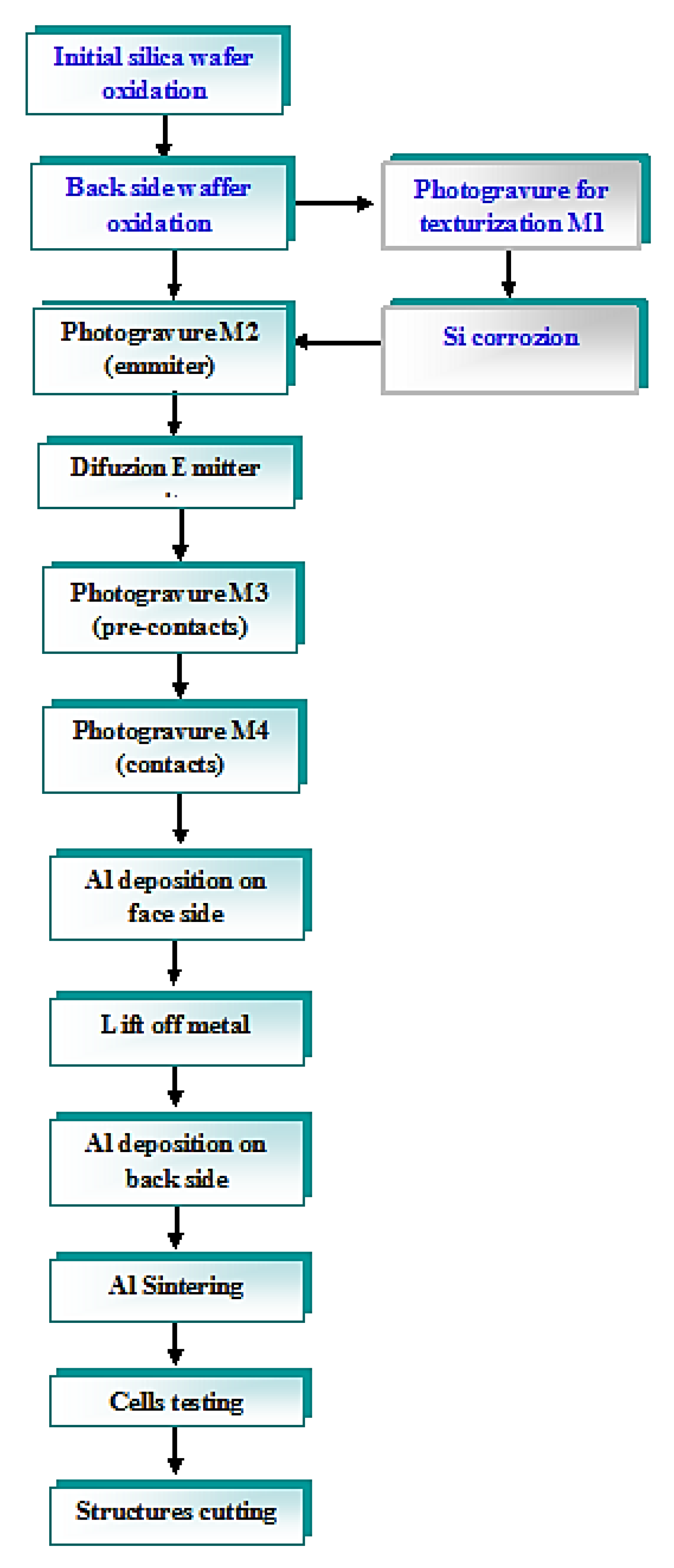
2.1. Technology Used for Photovoltaic Cells Fabrication
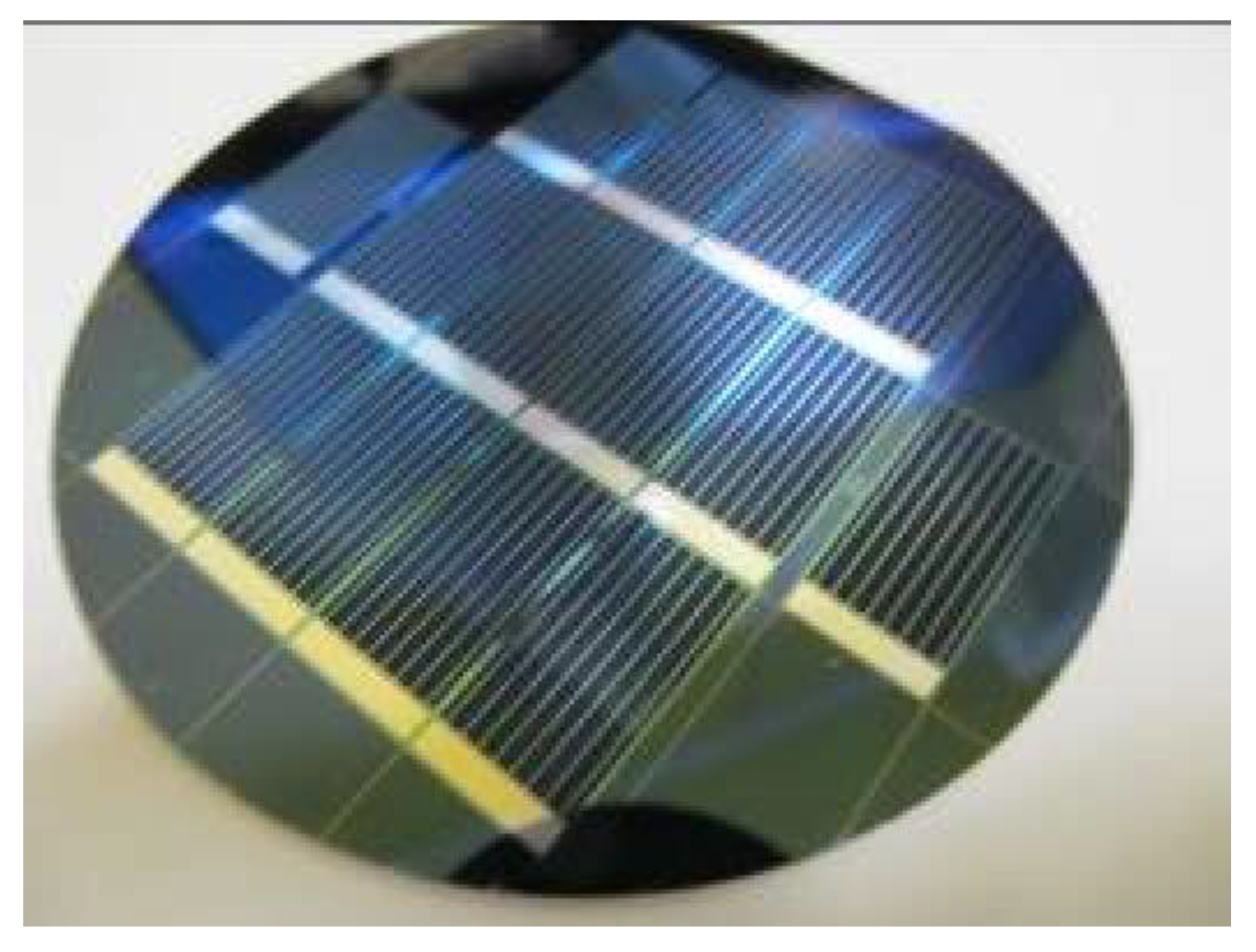
The manufacturing technology that was used for the PV cell structures included four levels of masking: mask M1, which was used to obtain the textured surface of the structure, mask M2, which was used to obtain an active area n+ diffusion, mask M3, which was used for pre–contact/collection electrodes, and mask M4, which was used for the metal contacts. The overlap of these masks was controlled using a group of alignment signs that were located on the diagonal of the plate at a distance of 5 cm to the primary alignment cross. An image of the silica wafer with the photovoltaic cells before separation is presented in
Figure 4.
The micro-texturing of the active surface in order to reduce the reflection losses at the radiation incident surface was performed by a photolithographic process through the oxide mask realised after the diffusion of boron. An image of the pyramids obtained on the surface of photovoltaic cells is presented in
Figure 5.
Technological process of photovoltaic cell fabrication is presented in
Figure 6.
The classic wing manufacturing technology that has been used so far does not allow for the integration of photovoltaic cells, which there is a high probability of during vacuuming due to the pressure exerted on the photovoltaic cells, causing them to exceed the maximum allowable deformation on the areas where the curvature of the wing is greater than 0.5 mm. Following the research and studies that have previously been performed, the necessary changes in the technological process were determined in order to ensure the integration of the cells in the wing without destroying them.
The wing lamination would be conducted in two distinct stages:
For this, a technology that allows the incorporation of photovoltaic cells in the protective resin layer that covers the outer surface of the wing was developed, and it is presented in
Figure 7.
In the first step of the rolling process, the photovoltaic cells are incorporated in the epoxy resin, eliminating the excess resin, in order to obtain a structure with a minimum thickness and a minimum weight. For this, a technological process similar to “resin infusion” was used, in which resin is introduced through the lower part of the mould, and the surplus is extracted on the edges (flight board and wing attack board) using a perforated extraction tube. The cells represent the first layer followed by a layer of perforated foil, which plays the role of letting the excess resin come out. This is followed by a layer of hard foil that is smaller than the perforated foil, which has a double role: to channel the resin to the upper extraction areas and to ensure a flat surface (the hard material prevents copying of irregularities of cells and electrical connections) on which a layer of the composite material can be applied. This film has the role of protecting the separation plane of the mold and is removed before rolling the resistance structure. The next layer is made of an absorbent material that ensures the vacuum distribution over the entire surface of the wing and collects and channels the excess resin to the exhaust pipe. The vacuum is applied through this pipe, and a buffer tank is also provided to collect the excess rain. The last layer is used for insulation and covers the entire wing.
After the resin has hardened, the technological layers are removed, and the manufacture of the wing is continued by laminating the resistance structure over the resin layer and photovoltaic cells.
2.2. Wing Production and Results
Based on the developed technology, over 3000 micro-structured photovoltaic cells were produced and characterised.
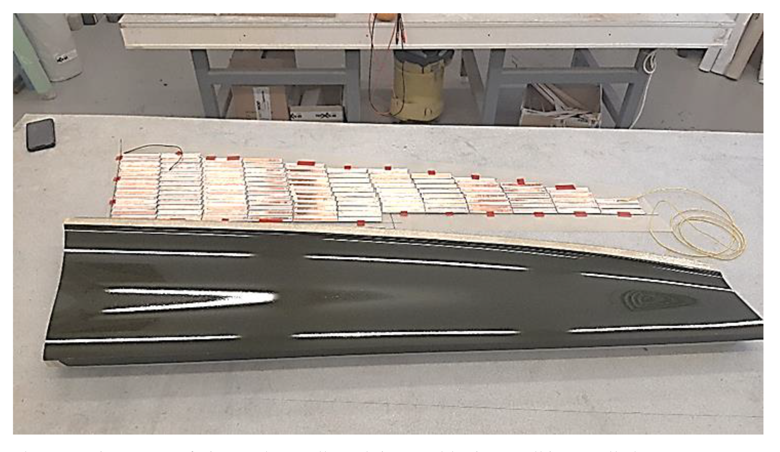
The first step during wing production was to connect the cells in the strings and rows in parallel, as presented in
Figure 8, and to produce the first layer of the wing.
After the wing fabrication process, the mould is removed, and the upper side of the wing is ready, with the cells embedded into the epoxy resin, as presented in
Figure 9.
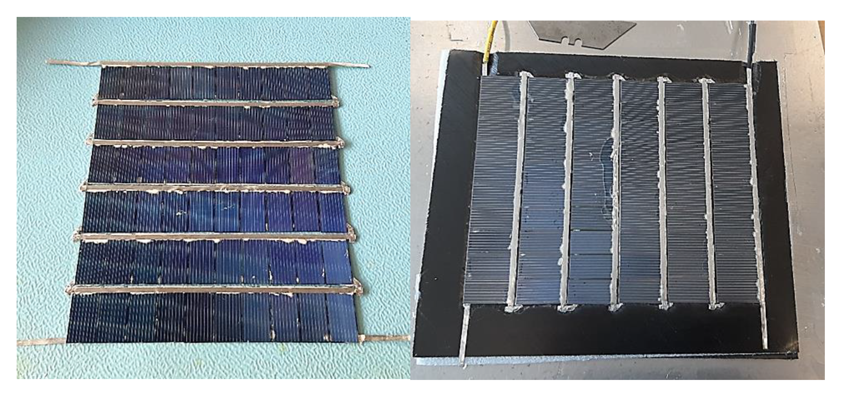
In order to conduct the required mechano-climatic tests for the produced structure, two small-sized demonstrators were produced, as presented in
Figure 10.


 ,
, 


