Abstract
In an effort to improve impact energy-absorption characteristics, this study introduces a cylindrical crash absorber (CAP) with discontinuous protrusions and a continuous local-expansion plastic-forming method for its manufacture. The mechanical properties of the cylindrical energy-absorption structure were modified by installing multiple particle protrusions on the cylinder sidewall to reduce the initial pickup load and improve the impact energy-absorption performance. To facilitate manufacture of the proposed CAP, a cylindrical rubber piece was placed into a cylindrical tube and pressure was applied to the rubber from both ends of the tube. The CAP was formed by the bulging force of the rubber. The formability was verified by developing a successive local bulge-forming experimental device and comparing the manufactured CAP with the results of numerical simulations. Testing of quasi-static collapse conducted on a CAP manufactured using this device verified the effectiveness of the proposed CAP design and its plastic-forming method. It was determined that this design reduced the initial peak load, and the crash absorber could maintain stability over a long, continuous distance during crushing deformation.
1. Introduction
In industrial fields, there are many application examples of crash energy absorbers [1,2,3]. Therefore, it is necessary to develop high-performance crash energy absorbers that can maintain stable crushing deformation for as long as possible. In addition, high-quality processing with a simple method is an important research objective.
Yamashita et al. took a thin-walled structure with various cap sections as the object, carried out a detailed study using drop-weight experiments and finite-element method (FEM) analysis, and introduced basic research results for the influence of section shape and material properties [4,5]. Li et al. combined multi-cell and multi-corner configurations to enhance the crashworthiness of a thin-walled tube, but previous studies demonstrated that the initial peak load of the crushing reaction force could be further increased [6,7]. Axial loading has been performed with almost all types of conventional pipe, including round pipes [8,9], triangle pipes [10,11], square pipes [12,13], pentagons [14], hexagonal pipes [15,16], and octagonal tubes [17,18]. To improve the phenomenon of transverse bending in the crushing deformation process, Hagiwara et al. proposed a crash absorber with a long compression distance. By introducing grooving in the abdomen and bulging nodes, deformation in the concertina mode was achieved; however, this design could not overcome the defect of an excessive initial peak load during the crashing process [19,20]. Hagiwara et al., therefore, explored the use of a reversed-spiral origami structure along the direction of the perimeter to obtain characteristics of long-lasting crushing deformation. The initial peak crushing force was eased [21,22], but the mean crashing force was lower and the energy absorption declined. From these points, it is evident that the de-formation mode can be effectively controlled if an origami structure is applied to a crash absorber. Further studies showed that the performance of a crash absorber can be improved by inserting various patterns along the sidewall [23,24,25]. Zhao et al. investigated the crash characteristics of a half-cut-type side-member structure, using an optimal design method to improve the energy-absorption ability [26]. These research works adopted cylindrical thin-walled structures, using origami engineering as a front side part, and developed an optimization system for a cylindrical thin-walled structure using origami engineering to improve crashing performance. [27,28].
Although an origami crash absorber is reasonable, and its energy-absorption characteristics have proved better than those of traditional structures, manufacturing problems persist because of its complex sectional shape. Its shape and characteristics are close to those of a cylinder, so manufacturing inspired by hydroforming has been used. Kong et al. conducted an optimization analysis to improve the formed thickness and avoid fractures [29]. Liang et al. designed and studied a reverse torsion-type crash energy-absorption structure, obtained by an inexpensive partially heated torsion manufacturing method [30,31]. In summary, origami crash absorbers have great potential to reduce the initial peak force and improve deformation stability and, thus, have been attracting increasing attention.
The purpose of this research was to improve the stability of the energy absorption of a thin-walled tube structure and provide some insights for the designer of a thin-walled structure that requires local expansion, and mainly includes the following three aspects: (1) According to the variation law of the ideal energy absorption curve, we designed a cylindrical crash absorber with discontinuous protrusions (CAP). The protrusions can reduce the initial peak force effectively, and the PWS structure formed in the later stage can improve the phenomenon of attenuation. (2) We proposed a new processing method, the successive partial rubber-bulging method, and used this method for cap processing. (3) We analyzed the influence of the protrusions on the energy absorption characteristics through an axial crush experiment and finite element software and analyzed the new collapse mode PWS formed in the process.
2. Materials and Methods
2.1. Cylindrical Crash Absorber with Discontinuous Protrusions
In general, the deformation–crash-load curve of a crash absorber during the entire crashing process can be plotted as the blue line shown in Figure 1. The horizontal axis denotes the effective deformation distance, and the vertical axis stands for the crushing load. It can be observed that the reaction force has a significant growth in the early stages and a greater attenuation occurs in the subsequent period. The initial peak load is determined by the buckling load of the crash absorber when the initial buckling occurs. To reduce the damage caused by an impact, the crash absorber is usually designed to reduce the initial peak load. As shown in Figure 1, the area between the crushing load and the horizontal axis is equal to the energy absorption, so this shape is regarded as an ideal crash absorber. A displacement–crash-load curve that approaches an approximate straight line indicates a better energy-absorption efficiency and good cushioning characteristics.
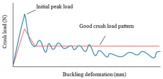
Figure 1.
Evolution of crash-loading during buckling deformation.
The initial peak load of the reactive crushing force is relatively high when a cylinder is used as a crash absorber, and the crashworthiness is unstable, owing to changes in the crushing folds produced in the crushing process. Inspired by the good crush-load pattern shown in Figure 1, a new CAP design is proposed. No similar structures have been reported in the literature previously. The CAP consists of a cylindrical tube with several discontinuous protrusions that are equidistantly spaced along the axial direction. The advantages of changing from the cylinder shown in Figure 2a to the CAP shown in Figure 2b are as follows: first, the initial peak crushing load can be reduced; second, the distribution of crushing wrinkles can be controlled by setting the positions of the equidistant protrusions arranged along the sidewall. Furthermore, as the crushing deformation progresses, the crushing deformation wrinkles on the sidewall can form an intersection along the axial direction, as shown in Figure 2c, and, therefore, contribute to a longer crushing distance.
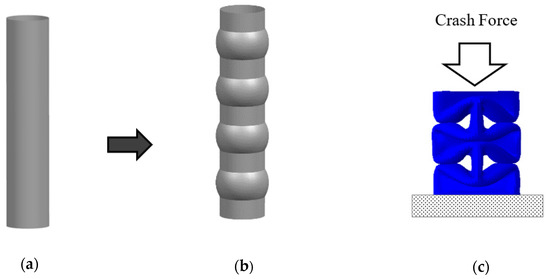
Figure 2.
Proposed CAP design and its crushing deformation pattern. (a) cylinder (b) CAP (c) crush deformation.
The dimensions of the CAP studied in this paper are shown in Figure 3. The diameter of the unformed cylinder was 50 mm, the diameter of the partial protrusions was 60 mm, the distance between the two protrusions was 22 mm, and the length of each protrusion was 31.67 mm. The initial wall thickness was 1.2 mm.
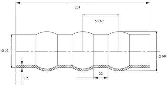
Figure 3.
Shape and dimensions of the CAP used in this study.
2.2. Successive Partial Rubber-Bulging Method
In this study, a stretching molding method using a continuous solid rubber tube is proposed, as shown in Figure 4. A cylindrical rubber piece and metal rod were placed into a cylindrical tube and a molding die was provided on the outside. In the molding process, shown in Figure 5, pressure was imposed on the round metal bar in the cylindrical tube from both ends, to cause the rubber to outwardly expand. Figure 4a provides a schematic diagram of the first stage of CAP processing. The first step of processing is completed once the rubber expands, and the outer wall of the round tube is attached to the mold. In the subsequent processing, shown in Figure 4b, the formed part is placed in position ①, which plays a role in location. Consistent with the processing method of the first stage, the next protrusion will take place in position ②. In this way, the final CAP is obtained by sequentially repeating this molding process in the axial direction. Figure 4c shows the cylindrical material, rubber, and round bar used in the actual processing.
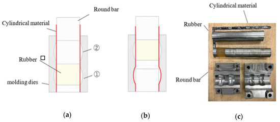
Figure 4.
Sequential partial bulging-plastic molding method using rubber. (a) First part molding (b) Others part molding (c) Tools used for molding.
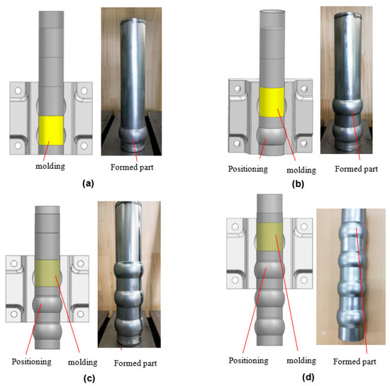
Figure 5.
Sequential process of the partial bulging-plastic molding method. (a) First step (b) Second step (c) Third step (d) Fourth step.
The experimental device and die for the successive partial rubber-bulging method are shown in Figure 6. The manual hydraulic jack used for molding (KPA-30S20, Osaka Jack Co. Osaka, Japan) had a pressure of 30 t. When clamping the mold, the use of wedge-shaped positioning parts on both sides ensured the accurate positioning of the molding surface. The mold was tightened through the four corner bolt holes. The actual experimental CAP obtained is shown in Figure 7. The processing parameters are shown in Table 1.
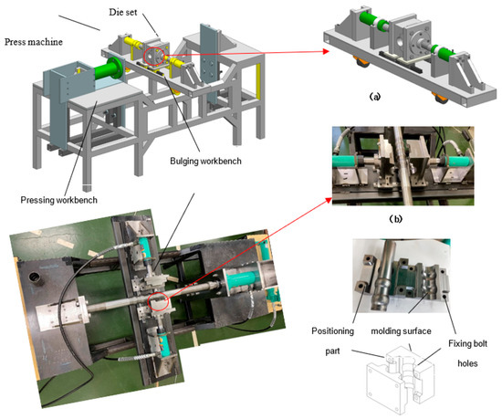
Figure 6.
Mold setting and device used for the successive partial rubber-bulging method. (a) state of clamp (b) state of opening.
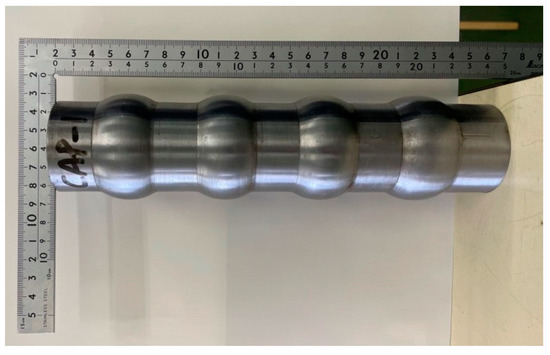
Figure 7.
Photograph of experimental CAP.

Table 1.
Technological Parameters of Manufacture.
3. Results
3.1. Formation Analysis
To verify the molding performance of this successive partial rubber-bulging method, an FEM analysis model was used for a formation simulation, as shown in Figure 8. The model comprised three parts: a cylindrical rubber piece, the cylindrical material, and the mold. The rigid body model was applied to the mold, the Mooney–Rivlin material model [20] was applied to the cylindrical rubber tube, and the elastoplastic material model was applied to the cylindrical tube. The explicit finite element code Abaqus was used to simulate the experimental process. In the simulation, the cylindrical rubber piece was placed into the cylindrical tube and the mold was placed on the outside of the tube. The tube wall was meshed using four-node curved S4R shell elements. The relationship between the tube and the rubber and mold was defined using ‘surface-to-surface’ contact. A hard contact was applied to the column wall to avoid interpenetration of the folding generated during axial compression. The dynamic and static coefficients of the friction coefficients of the contact surface of each part were set to 0.2 and 0.15. The load condition for molding was referenced with respect to that read from the pressure gauge of the manual hydraulic jacket during the actual processing, as shown in Figure 6; a load of 100 kN was uniformly applied from both ends of the cylindrical rubber tube. Several simulations were first run to conduct a convergence test, and finally an element size of 2 mm was determined due to its acceptable accuracy and computational cost. The total number of nodes in the analysis model was 141,368 and the total number of elements was 54,477.
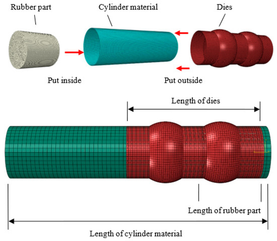
Figure 8.
Model used for finite-element simulation of the CAP.
The true stress-plastic strain curve of the STKM11A was obtained by processing data from the experiment, as shown in Figure 9. The properties of the CAP are as follows: density ρ = 7800 kg/m3, Young’s modulus E = 213 GPa, Poisson’s ratio ν = 0.3, yield stress 270 MPa, and ultimate stress 295.8 MPa.
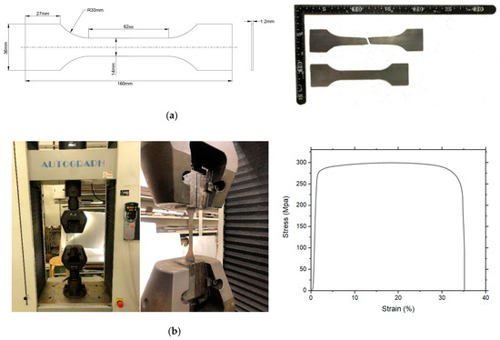
Figure 9.
Model used for finite-element simulation of the CAP. (a) geometry of specimen (b) geometry of specimen for test.
The thickness distribution of the formed tube along the axial direction of the CAP is shown in Figure 10. The red line represents the simulation results, and the blue line denotes the experimental results; the ○ and Δ symbols represent the respective thickness measurement points. In the rubber-bulging method, five samples were manufactured to measure the thickness using an outer dial caliper gauge (BO type) with an accuracy of 0.025 mm, and the average of these tests was taken. The numerical simulation values were very consistent with actual measured values: for the smallest wall thickness, which occurred in the center of a protrusion, the numerical simulation gave a value of 1.083 mm, and the actual measured value was 1.090 mm. Relative to the wall thickness of 1.20 mm before forming, the calculated maximum thinning rate was (1.20 − 1.09)/1.20 = 10.1%. This result proved that this successive partial rubber-bulging method is reliable for the processing of the CAP [32,33].
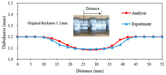
Figure 10.
Modelled and measured thickness distributions of the formed CAP.
3.2. Axial Crushing Experiment
To verify the crushing performance of the CAP produced by this successive partial rubber-bulging method, a crushing test was conducted using an auto-cupping machine (AG-300KAG, Shimadzu Corp., Kyoto, Japan), as shown in Figure 11. When a compressive load was applied in the axial direction and compression deformation progressed to a certain extent, a naturally formed partial wall structure (PWS) that intersected at right angles the central axis of the CAP was observed. Through mutual support of this PWS, the crushing deformation could be sustained for a long crushing compression distance. This collapse behavior is considered beneficial for improving the crashing energy absorption.
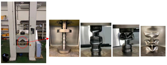
Figure 11.
Photographs showing crushing experimental configuration and various crushed states of the CAP during its deformation.
The FEM was used to simulate the collision deformation process of the CAP, to verify its crushing performance, as shown in Figure 11. A numerical simulation model is shown in Figure 12. Rigid plates were attached to the upper and lower ends of the CAP, and an evenly distributed displacement load was applied on the upper plate along the axial direction. The CAP was simulated by using four-node curved S4R shell elements. Surface-surface contact was applied between the impacting rigid plate and the CAP. The friction coefficient was taken as 0.3. In order to save computing resources, different mesh sizes, such as 10 mm × 10 mm, 8 mm × 8 mm, 6 mm × 6 mm, and 4 mm × 4 mm, were tried to check the convergence of the finite element model. The results show that a mesh size of 4 mm × 4 mm can fully meet the requirement of simulation accuracy. Combined with the actual experimental conditions, several simulations were run to conduct a convergence test, and a distance for the displacement load of 180 mm was determined. The dimensions of the numerical simulation model were the same as those shown in Figure 3. The total number of nodes was 3001, and the total number of elements was 2867. The samples used in this crushing experiment were the same as those in the previous processing and so were the material properties.
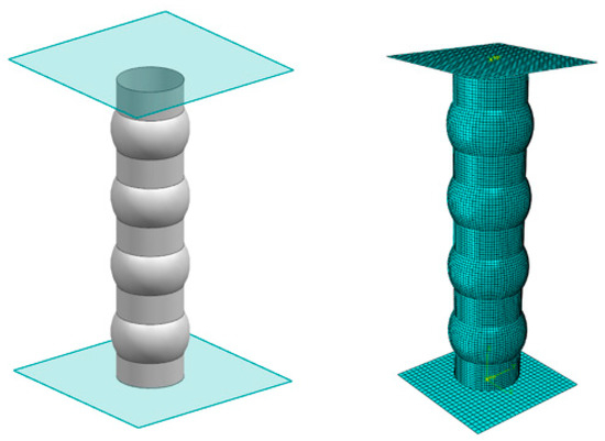
Figure 12.
Model used for simulation of the crushing experiment of the CAP, and its states during deformation.
By using a rubber-bulging method, samples of the CAP were manufactured. In the crushing experiments, five samples were tested, and the error rates of the other samples were within 5%. The most similar one was picked as a result in this research. Comparison of the numerical simulation and experimental results for the crushing load as a function of crushing deformation is shown in Figure 13. The numerical analysis shows that, as the compression deformation progressed, PWS were naturally formed, which intersected at right angles along the central axis. This is consistent with the experimental results, which confirmed the general accuracy of the collapse experiment.
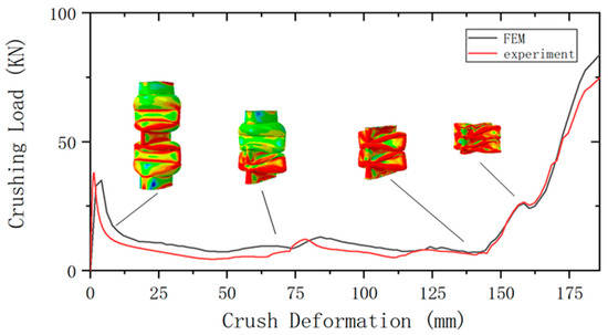
Figure 13.
Comparison of the modelled and experimental crushing load distributions of the CAP and states during its deformation.
According to Figure 13, in the initial stage of crushing deformation, as the axial compression force continued to increase and the initial buckling occurred, an initial crushing peak load appeared. Thereafter, crushed wrinkles appeared in the bulging part and the unformed part, which acted as inducement to each other during the process. Owing to the mutual support of the subsequently created PWS, the crushing load of the CAP stabilized during this period at about 25 kN. When the crushing deformation distance exceeded 158 mm, the crushing load again increased, when the PWS formed in each stage started to contact each other.
The displacement–crushing-load diagram of Figure 13 shows almost the same characteristics as those of the ideal crash absorber shown in Figure 1. In addition, the crushing load increased again in the latter half of the crushing deformation process. To explain this phenomenon in detail, corresponding photos from the experiment will be used for discussion, as shown in Figure 14.
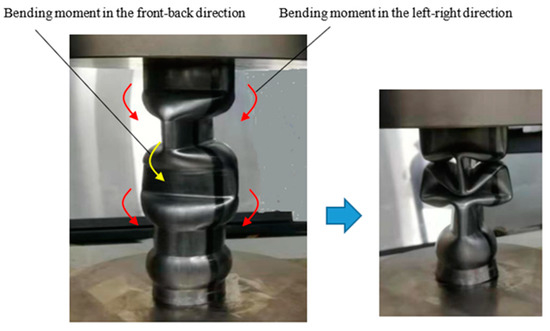
Figure 14.
Orthogonal partial wall structures during the crush deformation of the CAP.
Under an axial compressive load, the cylindrical part of the sidewall deformed, from a circular cross-section, to an elliptical cross-section, due to the compression force, and multiple PWS formed in sequence. When a protrusion was compressed downward by the elongated PWS, a bending moment was generated, as shown in Figure 14, and a new PWS formed along the lower cylindrical part in the orthogonal direction.
4. Discussion
4.1. Crash Absorber Mechanism
Crushing deformation occurs in a repetitive manner. When all protrusions have collapsed, the crushing deformation is only continued by the PWS, which cross each other perpendicularly. The folded edges of the PWS ensure structural stability, similar to that of a partial truss configuration, as shown by the red lines in Figure 15. In addition, a new buckling deformation occurs in the central part of the PWS, which was thought to cause the crushing load to increase again in the latter half of the crushing deformation, as shown in Figure 13.
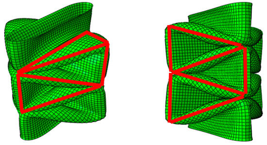
Figure 15.
Partial truss configuration with orthogonal wall structures.
As shown in Figure 13, a slightly larger initial peak load appeared in the initial stage of the crushing deformation, due to the axial compression force, and because this is the first buckling deformation of the CAP. Generally, when the crushing load is small and lower than the initial peak load, the CAP can be elastically deformed like an ordinary spring and act as a crash absorber; however, buckling of the CAP occurred as soon as the crushing load became larger and exceeded the initial peak load. Therefore, the subsequent crushing deformation, which is accompanied by the occurrence of wrinkles, can play a decisive role as a safety device in crashing energy absorption.
4.2. Comparison with a Cylinder
The unprocessed cylindrical structure shown in Figure 2a was subjected to crushing deformation experiments and numerical simulation under the same conditions as the CAP. Figure 16 shows the results of the crushing deformation of the cylindrical structure. This showed the characteristics of small buckling wrinkles, which accumulated along the circumferential direction of the cylindrical structure during the entire crushing deformation process. The deformed tube shapes or collapse modes in the experiment and simulation were compared at four displacement points, as presented in Figure 17. The initial peak load of the cylindrical structure at the initial stage of crushing deformation was relatively large. Once the initial peak load was exceeded, crushing wrinkles occurred, accompanied by a high rate of load fluctuation. A vertical fluctuation of crushing load corresponded to the appearance of a buckling wrinkle. Load capacity fluctuations are usually used to evaluate the stability of an energy-absorption method [34,35]. Therefore, this crushing deformation mode is considered unstable. In practice, a cylinder is rarely used directly as a crash absorber.
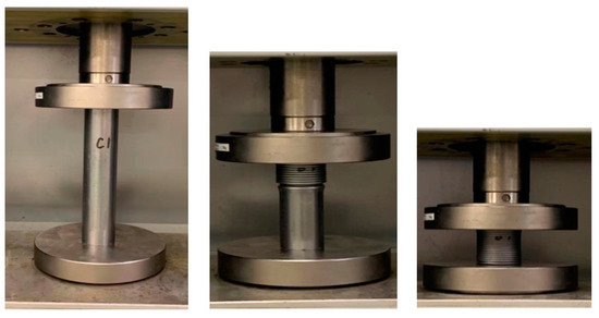
Figure 16.
Photographs showing the crushing experimental configuration of the cylinder and various crushed states during its deformation.
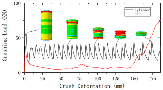
Figure 17.
Crushing load distribution of the cylinder, and its states during its deformation.
In contrast, the CAP crushing load distribution curve (Figure 13) showed that the structure could effectively reduce the initial peak load; once the initial peak load was exceeded, relatively stable and long-lasting crushing deformation occurred, accompanied by a low rate of fluctuation of the load.
In summary, the collapse mode and folds of the CAP proposed in this study can be predicted. In addition, by setting the relative configurations of the cylindrical and protruding parts, the initial peak load can be controlled. This work provides a good reference for design selection for future researchers, in order to develop a more stable high-performance crash absorber. In particular, the study of the naturally formed PWS that occur during the process of CAP crushing and deformation can contribute to designs aimed at further improving CAP crushing performance.
5. Conclusions
To obtain a more stable cushioning effect, to minimize the damage caused by an impact collision, we designed a new type of cylindrical crash absorber (CAP) with discontinuous protrusions, and developed a CAP manufacturing device that uses a successive partial rubber-bulging method. The performance was verified through trial experiments and numerical simulation, and the following conclusions can be drawn:
(1) When a cylinder is used as a crash absorber, the initial peak load is relatively large, and the unstable cushioning performance causes a high rate of load fluctuation. To mitigate these problems, we proposed a CAP consisting of a cylindrical tube with several discontinuous protrusions that are equidistantly spaced along the axial direction. Through crushing deformation experiments and numerical simulation, it was determined that this design reduces the initial peak load, and the crash absorber maintains stability over a long continuous distance during crushing deformation.
(2) To produce this CAP using a simple and inexpensive method, we proposed a successive partial rubber-bulging method, based on the elasticity of rubber. The molding characteristics were verified by simulating the process technique, and an actual mold and processing device were used to produce a CAP. The measured wall thickness distribution of the manufactured CAP was almost the same as that of the numerical simulation. The maximum thickness thinning rate of the molded CAP was 10.1%. This proved that the processing method and manufacturing equipment are reliable.
(3) In the second half of the CAP compression deformation, the cylindrical part of the CAP becomes a PWS due to compression. This generates a bending moment below the connecting protrusion, which forms two adjacent PWS, orthogonal to each other. For the first time, we have clarified the mechanism by which the crushing load of a CAP then increases again, which is attributed to a structure that consists of the folded edges of the PWS; similar to a spatial truss.
A cylindrical crash absorber with discontinuous protrusions and its manufacture using a successive partial rubber-bulging method are proposed, and the obtained results can be applied to the development of crash absorbers with other cross-sectional shapes.
Author Contributions
D.L. contributed to the study concepts, study design, and manuscript preparation, W.X., J.F., W.Z. and N.K. contributed to the data acquisition and manuscript editing, X.Z. contributed as the guarantor of integrity of the entire study. All authors have read and agreed to the published version of the manuscript.
Funding
This research was funded by THE AMADA FOUNDATION, grant number AF-2020007.
Institutional Review Board Statement
Not applicable.
Informed Consent Statement
Not applicable.
Data Availability Statement
Data available in a publicly accessible repository.
Acknowledgments
We thank Kathryn Sole (https://en-author-services.edanz.com/ac, accessed on 10 October 2021) for editing a draft of this manuscript.
Conflicts of Interest
The authors declare no conflict of interest.
References
- Takayuki, F.; Takeshi, F.; Yamasaki, F.; Toshiaki, U. Development of Collision Energy Absorption Parts. Trans. Soc. Automot. Eng. Jpn. 2015, 46, 799–804. [Google Scholar]
- Alghamdi, A.A.A. Collapsible impact energy absorbers: An overview. Thin-Walled Struct. 2001, 39, 189–213. [Google Scholar] [CrossRef]
- Baroutaji, A.; Sajjia, M.; Olabi, A.G. On the crashworthiness performance of thin-walled energy absorbers: Recent advances and future developments. Thin-Walled Struct. 2017, 118, 137–163. [Google Scholar] [CrossRef]
- Yamashita, M.; Goto, M.; Takahashi, T.; Sawairi, Y. Axial impact crushing of strength members with various hat-shaped cross sections (1st report, experiment using a falling weight impact tester). Proc. Jpn. Soc. Mech. Eng. A 2002, 68, 140. [Google Scholar]
- Yamashita, M.; Goto, M.; Sawairi, Y. Axial impact crushing of strength members with various hat-shaped cross sections (2nd report, FEM simulation of crushing process). Proc. Jpn. Soc. Mech. Eng. A 2002, 68, 37. [Google Scholar]
- Li, Z.; Ma, W.; Xu, P.; Yao, S. Crashworthiness of Multi-cell Circumferentially Corrugated Square Tubes with Cosine and Triangular Configurations. Int. J. Mech. Sci. 2020, 165, 105205. [Google Scholar] [CrossRef]
- Li, Z.; Yao, S.; Ma, W.; Xu, P.; Che, Q. Energy-Absorption Characteristics of a Circumferentially Corrugated Square Tube with a Cosine Profile. Thin-Walled Struct. 2019, 135, 385–399. [Google Scholar] [CrossRef]
- Gao, G.; Guan, W.; Li, J.; Dong, H.; Zou, X.; Chen, W. Experimental investigation of an active–passive integration energy absorber for railway vehicles. Thin-Walled Struct. 2017, 117, 89–97. [Google Scholar] [CrossRef]
- Wang, Y.; Zhai, X.; Ying, W.; Wang, W. Dynamic crushing response of an energy absorption connector with curved plate and aluminum foam as energy absorber. Int. J. Impact Eng. 2018, 121, 119–133. [Google Scholar] [CrossRef]
- Fan, Z.; Lu, G.; Yu, T.X.; Liu, K. Axial Crushing of Triangular Tubes. Int. J. Appl. Mech. 2013, 5, 1350008. [Google Scholar] [CrossRef]
- Wang, P.; Zheng, Q.; Fan, H.; Sun, F.; Jin, F.; Qu, Z. Quasi-Static Crushing Behaviors and Plastic Analysis of Thin-Walled Triangular Tubes. J. Constr. Steel Res. 2015, 106, 35–43. [Google Scholar] [CrossRef]
- Fu, J.; Liu, Q.; Liufu, K.; Deng, Y.; Fang, J.; Li, Q. Design of bionic-bamboo thin-walled structures for energy absorption. Thin-Walled Struct. 2019, 135, 400–413. [Google Scholar] [CrossRef]
- Pang, T.; Zheng, G.; Fang, J.; Ruan, D.; Sun, G. Energy absorption mechanism of axially-varying thickness (AVT) multicell thin-walled structures under out-of-plane loading. Eng. Struct. 2019, 196, 109130. [Google Scholar] [CrossRef]
- Song, J.; Zhou, Y.; Guo, F. A Relationship between Progressive Collapse and Initial Buckling for Tubular Structures under Axial Loading. Int. J. Mech. Sci. 2013, 75, 200–211. [Google Scholar] [CrossRef]
- Zhang, X.; Zhang, H. Experimental and Numerical Investigation on Crush Resistance of Polygonal Columns and Angle Elements. Thin-Walled Struct. 2012, 57, 25–36. [Google Scholar] [CrossRef]
- Fan, Z.; Lu, G.; Liu, K. Quasi-Static Axial Compression of ThinWalled Tubes with Different Cross-Sectional Shapes. Eng. Struct. 2013, 55, 80–89. [Google Scholar] [CrossRef]
- Xiang, J.; Du, J.; Li, D.; Scarpa, F. Numerical analysis of the impact resistance in aluminum alloy bi-tubular thin-walled structures designs inspired by beetle elytra. J. Mater. Sci. 2017, 52, 13247–13260. [Google Scholar] [CrossRef]
- Mou, H.; Xie, J.; Zou, J.; Feng, Z. Experimental researches on failure and energy absorption of composite laminated thin-walled structures. J. Compos. Mater. 2020, 54, 4253–4268. [Google Scholar]
- Ichiro Hagiwara, M.T.; Yoshihiro, S. Impact crushing analysis of thin-walled box-shaped straight members by the finite element method. Proc. Jpn. Soc. Mech. Eng. A 1989, 55, 1407. [Google Scholar]
- Kitagawa, Y.; Hagiwara, I. Impact crushing analysis of thin-walled arbitrary cross-sectional shape members by the finite element method. Proc. Jpn. Soc. Mech. Eng. A 2007, 43, 1135. [Google Scholar]
- Wu, Z.; Hagiwara, I.; Tao, X. Optimization of Crash Characteristics of the Cylindrical Origami Structure. Int. J. Veh. Des. 2007, 43, 66. [Google Scholar] [CrossRef]
- Hagiwara, I.; Nadayoshi, S. Crushing analysis of cylindrical structures using origami engineering. Proc. Soc. Automot. Eng. Jpn. 2003, 34, 145. [Google Scholar]
- Yao, S.; Zhu, H.; Liu, M.; Li, Z.; Xu, P. Energy Absorption of Origami Tubes with Polygonal Cross-Sections. Thin-Walled Struct. 2020, 157, 107013. [Google Scholar] [CrossRef]
- Ma, J.; You, Z. Energy Absorption of Thin-Walled Square Tubes with a Prefolded Origami Pattern—Part I: Geometry and Numerical Simulation, Mechanics of Advanced Materials and Structures. ASME J. Appl. Mech. 2014, 81, 011003–011011. [Google Scholar] [CrossRef]
- Zhou, J.; Dong, C.; Chen, B.; Niu, X. Design and Numerical Simulation of Pyramidal Prefolded Patterned Thin-Walled Tubes. Adv. Mater. Sci. Eng. 2021, 2021, 6614381. [Google Scholar] [CrossRef]
- Zhao, X.; Hu, Y.; Hagiwara, I. Optimal design of collision crushing characteristics of cylindrical thin-walled structures using origami engineering. Proc. Jpn. Soc. Mech. Eng. A 2010, 76, 10. [Google Scholar] [CrossRef][Green Version]
- Zhao, X.; Hu, Y.; Ichiro, H. A study on the collision crushing energy absorption performance of half-split automobile side members with the assistance of origami engineering. Proc. Jpn. Soc. Mech. Eng. A 2010, 76, 1131. [Google Scholar] [CrossRef]
- Wu, Q.; Zhang, H.; Zhao, W.; Zhao, X. Shape Optimum Design by Basis Vector Method Considering Partial Shape Dependence. Appl. Sci. 2020, 10, 7848. [Google Scholar] [CrossRef]
- Kong, C.; Zhao, X.; Hagiwara, I. Hydromolding Process of Manufacturing for Reverse Spiral Origami Structure. Int. J. Veh. Perform. 2017, 3, 347. [Google Scholar] [CrossRef]
- Liang, D.; Kong, Y.; Zhao, J.; Hagiwara, I. Inverted torsion type energy absorption structure and its inexpensive partial heating torsion processing method. Proc. Jpn. Soc. Mech. Eng. A 2021, 87, 20–00425. [Google Scholar]
- Iizuka, H.; Yamashita, Y. Identification of mechanical properties of rubber materials and their use for FEM analysis. J. Jpn. Rubber Assoc. 2004, 77, 306. [Google Scholar] [CrossRef]
- JSP-Form Processing. Press Forming of Plate Materials; Corona Publishing Co, Ltd.: Tokyo, Japan, 2020; p. 34. [Google Scholar]
- JSP-Form Processing. Tube Forming; Corona Publishing Co, Ltd.: Tokyo, Japan, 2019; p. 8. [Google Scholar]
- Xiang, Y.; Wang, M.; Yu, T.; Yang, L. Key performance indicators of tubes and foam-filled tubes used as energy absorbers. Int. J. Appl. Mech. 2015, 7, 1550060. [Google Scholar] [CrossRef]
- Wu, S.; Li, G.; Sun, G.; Wu, X.; Li, Q. Crashworthiness analysis and optimization of sinusoidal corrugation tube. Thin-Walled Struct. 2016, 105, 121–134. [Google Scholar] [CrossRef]


Publisher’s Note: MDPI stays neutral with regard to jurisdictional claims in published maps and institutional affiliations. |
© 2021 by the authors. Licensee MDPI, Basel, Switzerland. This article is an open access article distributed under the terms and conditions of the Creative Commons Attribution (CC BY) license (https://creativecommons.org/licenses/by/4.0/).