Article

SMCSPO-Based Robust Control of AUV in Underwater Environments including Disturbances

1
Division of Robotics Convergence, Pusan National University, 2, Busandaehak-ro 63beon-gil, Geumjeong-gu, Busan 46241, Korea
2
School of Mechanical Engineering, Pusan National University, 2, Busandaehak-ro 63beon-gil, Geumjeong-gu, Busan 46241, Korea
3
SPENALO National Robotics Research Center, Pusan National University, 2, Busandaehak-ro 63beon-gil, Geumjeong-gu, Busan 46241, Korea
4
Agency for Defense Development, 19, Hyeon-dong, Jinhae-gu, Changwon-si 51678, Gyeongsangnam-do, Korea
5
Department of Mechanical and Automotive Engineering, Jeonju University, 3, Hyoja-dong 3-ga, Wansan-gu, Jeonju-si 55069, Jeollabuk-do, Korea
*
Author to whom correspondence should be addressed.
Appl. Sci. 2021, 11(22), 10978; https://doi.org/10.3390/app112210978
Submission received: 8 October 2021 / Revised: 12 November 2021 / Accepted: 18 November 2021 / Published: 19 November 2021

Abstract

:
In the underwater environment, robust control algorithms are required to control autonomous underwater vehicles (AUVs) at high speed while preventing large nonlinearities and disturbances. Sliding mode control (SMC) is a well-known robust control theory and has been widely used not only in AUV control but also in systems such as industrial robots which have high nonlinearity in their system dynamics. However, SMC has the disadvantage of causing chattering on the control input, and it is difficult to apply this method to the control fins of an AUV system that cannot move its fins at high speed underwater. In this work, a design for a sliding mode control with sliding perturbation observer (SMCSPO) algorithm is applied to AUVs, and the simulation results under underwater disturbance conditions are discussed. From simulation using MATLAB, it is confirmed that AUV control using SMCSPO shows better trajectory tracking control performance without chattering than PID control.

1. Introduction

An autonomous underwater vehicle (AUV) is a robot that autonomously explores underwater environments without an operator’s control. AUVs are being researched for the unmanned exploration of the underwater environment. When an AUV moves underwater, external forces such as added mass and drag force affect the operation of the AUV. In order to overcome the effects of various disturbances in the underwater environment, many studies have been carried out on the dynamics analysis and control theories of underwater vehicles [1,2,3,4,5,6].
Feldman proposed the dynamics equation of the underwater vehicle, which consists of axial-lateral-normal force and rolling-pitching-yawing moment equations [1]. Prestero derived and linearized the 6-DOF dynamics equation to conduct an experiment with an AUV to which a PID controller was applied [2]. Khan performed simulations using sliding mode control, integral sliding mode control, super twisting, and real twisting algorithms to control the lateral dynamics of an AUV and compared the results [3]. The real twisting algorithm showed the best performance in terms of the lateral dynamics of position and velocity control of the AUV of the proposed controllers. Taheri designed a thickness of a boundary layer and switching gain in the sliding mode control (SMC) algorithm to reduce the chattering phenomenon amplitude of the control input [4]. However, the chattering phenomenon is still observed in sliding mode control under strong disturbances.
The SMC algorithm is a robust control theory that has been studied for AUV control in an underwater environment with strong nonlinearities and disturbances [3,4,5,6]. However, SMC can cause the chattering phenomenon due to the use of high switching gain to suppress high uncertainty terms and disturbances when the nonlinear terms of the system dynamics are large. Chattering can adversely affect the control of underwater vehicles, and it can also overload the control fins due to chattering by high-frequency control input. Moura proposed a sliding perturbation observer (SPO) to compensate for the chattering weakness of SMC control [7]. The SPO can compensate the assumed uncertainties and disturbances by estimating the nonlinear terms of the system dynamics. Therefore, the magnitude of SMC control input can be reduced by compensating the estimated terms. This method significantly reduces chattering in strong nonlinear systems by reducing the high switching gain of the SMC. Sliding mode control with a sliding perturbation observer (SMCSPO) has been used in several studies to robustly control the system and estimate perturbations. In surgical robot [8,9,10], hydraulic servo system [11,12,13,14], robot manipulator [15,16], and hot rolling simulator [17] areas, SMCSPO estimated the assumed uncertainties and disturbances of the system and showed better control performance than SMC.
In this paper, an SMCSPO controller for AUVs is designed to increase the robustness of the orientation control of the vehicle, and its control performance is evaluated. In order to apply SMCSPO to the underwater vehicle, we derived the coefficients related to the underwater vehicle dynamics, which are required for the design of the robust controller. In addition, the control parameters of the SMCSPO are determined and the control stability is analyzed to ensure that the underwater vehicle can be stably controlled. To evaluate whether the SMCSPO controller is suitable for the control of an AUV, a MATLAB simulation is performed under several conditions and compared with the results of the PID controller. It is confirmed that the results using SMCSPO are superior to those using PID control, and the results show that the vehicle is stably controlled without chattering.
The rest of this paper is organized as follows. Section 2 introduces the dynamics equation and the perturbation terms of the underwater vehicle. In Section 3, the controller and observer of SMCSPO and PID controller are designed for AUV orientation control. Section 4 discusses the vehicle’s simulation conditions and compares each controller’s simulation results. Finally, this paper is concluded in Section 5.

2. Dynamics Modeling of AUV

2.1. Underwater Vehicle Dynamics

Figure 1 shows the coordinate systems representation of the AUV. The coordinate systems and dynamics equations were derived based on Prestero’s model [2]. The notation η = x ,   y ,   z ,   ϕ ,   θ ,   ψ describes the position and orientation of the vehicle with respect to the Earth-fixed reference frame, υ = u , v , w , p , q , r is the translational and rotational velocities of the vehicle with respect to the body-fixed reference frame, and τ = X , Y , Z , K , M , N is the total forces and moments acting on the vehicle with respect to the body-fixed reference frame.
The dynamics model of the AUV is as shown in (1) to (6) [18]. The shape of the AUV is assumed to be the shape of a torpedo, and six equations of motion are defined for surge, heave, sway, roll, pitch, and yaw directions.
m u ˙ = X u ˙ u ˙ + X u u u u X U U U U W B s i n θ ,
m v ˙ = Y v ˙ v ˙ + Y p ˙ p ˙ + Y r ˙ r ˙ + Y v v + Y p p + Y r r + W B c o s θ s i n ϕ + Y δ r U 2 δ r m u r ,
m w ˙ = Z w ˙ w ˙ + Z q ˙ q ˙ + Z w w + Z q q + W B c o s θ c o s ϕ + Z δ s U 2 δ s p m u q ,
I x x p ˙ = K v ˙ v ˙ + K p ˙ p ˙ + K r ˙ r ˙ + K v v + K p p + K r r + z B s i n ϕ y B c o s ϕ B c o s θ + K δ s U 2 δ s m ,
I y y q ˙ = M w ˙ w ˙ + M q ˙ q ˙ + M w w + M q q + x B B c o s θ c o s ϕ + z B B s i n θ + M δ s U 2 δ s p ,
I z z r ˙ = N v ˙ v ˙ + N p ˙ p ˙ + N r ˙ r ˙ + N v v + N p p + N r r + x B B c o s θ s i n ϕ + y B B s i n θ + N δ r U 2 δ r .
where τ = X , Y , Z , K , M , N is the hydrodynamic derivative coefficient values, which contain added mass, drag force, and fin lift force terms; U = u 2 + v 2 + w 2 is the operating speed of the vehicle; W is the weight of the vehicle; B is the buoyancy; I = I x x , I y y , I z z is the moment of inertia; and δ = δ s p , δ s m , δ r is the angle of the control fins of the vehicle. Here, δ r is the rudder angle of attack. The other control fins, δ s p and δ s m , are defined by the stern plane angle of attack as shown in (7) and (8).
δ s p = 1 2 δ s r + δ s l ,
δ s m = δ s r δ s l ,
where δ s r is the right stern plane angle of attack, and δ s l is the left stern plane angle of attack. The Earth-fixed coordinate system and the body-fixed coordinate system have the following transformation relation [2].
ϕ ˙ θ ˙ ψ ˙ = J η p q r ,
J η = 1 0 0 s i n ϕ t a n θ c o s ϕ s i n ϕ / c o s θ           c o s ϕ t a n θ s i n ϕ c o s ϕ / c o s θ .
If cos θ = 0 in (10), a singularity can occur. However, pitch angles of ±90 degrees are not considered in this study because these are abnormal AUV attitudes. Therefore, the pitch angle of the AUV is limited within ±90 degrees.

2.2. Definition of Perturbation of AUV Dynamics

The dynamics equations of the AUV contain nonlinear terms. Nonlinear terms including underwater disturbances may cause a chattering phenomenon due to the large switching gain used to suppress the nonlinear dynamics when the AUV is controlled using an SMC. The SPO estimates the nonlinear terms of the underwater vehicle dynamics and compensates the estimated nonlinear terms to the control input of the SMC to reduce the chattering phenomenon. The summation of nonlinear terms in (1) to (6) and (9) can be defined as the perturbation terms of SPO, as shown in (11) to (19).
Ψ u = X u u u u X U U U U W B s i n θ / m X u ˙ + d u ,
Ψ v = W B c o s θ s i n ϕ m u r / m Y v ˙ + d v ,
Ψ w = W B c o s θ c o s ϕ m u q / m Z w ˙ + d w ,
Ψ p = z B s i n ϕ y B c o s ϕ B c o s θ / I x x K p ˙ + d p ,
Ψ q = x B B c o s θ c o s ϕ + z B B s i n θ / I y y M q ˙ + d q ,
Ψ r = x B B c o s θ s i n ϕ + y B B s i n θ / I z z N r ˙ + d r .
Ψ ϕ = q s i n ϕ t a n θ + r c o s ϕ t a n θ + d ϕ ,
Ψ θ = q c o s ϕ r s i n ϕ + d θ ,
Ψ ϕ = q s i n ϕ / c o s θ r c o s ϕ / c o s θ + d ϕ ,
where D = d u , d v , d w , d p , d q , d r , d ϕ , d θ , d ϕ is the unknown disturbances of the underwater environment.

3. Controller and Observer Design

3.1. SPO
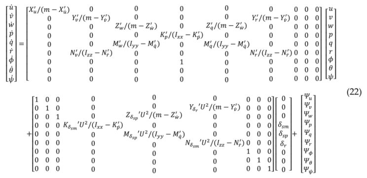
In this section, the structure of an SPO is briefly discussed [7]. The state space representation of the underwater vehicle dynamics is defined as shown in (20) and (21).
X ˙ 1 = X 2 ,
X ˙ 2 = A X 2 + Δ A X + B δ + D t ,
where X 2 = u , v , w , p , q , r , ϕ , θ , ψ = x 21 , x 22 , x 23 , x 24 , x 25 , x 26 , x 27 , x 28 , x 29 represents the translational velocities, rotational velocities, and the orientations of the vehicle; X = X 1 is an observable state variable and is the integral value of X 2 ; A X 2 and Δ A X are linear and nonlinear terms of dynamics, respectively; and B δ is the control input matrix of the underwater vehicle. By using the AUV dynamics in (1) to (6) and the defined perturbations terms in (11) to (19), Equation (21) can be expressed in the following matrix form.
Applsci 11 10978 i001
Perturbation can be defined as the summation of all nonlinear terms and disturbances in (21), as follows:
Ψ = Δ A X + D t ,
It is assumed that the perturbations are upper-bounded by a known continuous function of state [19]. For convenience, the perturbation terms and the linear terms of the system can be separated from the dynamics. An arbitrary positive number ( α 3 ) and a new control input ( U ¯ ) are defined to decouple the control variable.
A X ^ 2 + B δ = α 3 U ¯ ,
where X ^ 2 is the estimated state variable. Throughout the text, “~” refers to estimation errors, and “^” symbolizes the estimated quantity.
By the perturbation and new control input, the state space representation is replaced as follows:
X ˙ 1 = X 2 ,
X ˙ 2 = α 3 U ¯ + Ψ ,
Y = X 1 .
Using (23) and (24), (21) can be simplified as (26). A new state variable ( X 3 ) for deriving the perturbation from the sliding observer is defined as
X 3 = α 3 X 2 Ψ / α 3 .
The perturbation is calculated using (28). The perturbation of the entire sliding observer structure for monitoring the system states is given by
X ^ ˙ 1 = X ^ 2 k 1 s a t X ˜ 1 α 1 X ˜ 1 ,
X ^ ˙ 2 = α 3 U ¯ k 2 s a t X ˜ 1 α 2 X ˜ 1 + Ψ ^ ,
X ^ ˙ 3 = α 3 2 X ^ 3 + α 3 X ^ 2 + U ¯ .
The perturbation ( Ψ ^ ) can be calculated as
Ψ ^ = α 3 X ^ 3 + α 3 X ^ 2 ,
where k 1 ,   k 2 ,   α 1 ,   α 2 , and α 3 are positive constants of the sliding observer, and X ˜ i = X ^ i X i is the estimated error of the state variables. The saturation function in (29) and (30) is used to reduce chattering in the sliding surface. It is given by
s a t x ˜ 1 = x ˜ 1 / x ˜ 1 ,     i f   x ˜ 1 ε 0 x ˜ 1 / ε 0 ,     i f   x ˜ 1 < ε 0 ,
where ε 0 is the SPO boundary layer.

3.2. SMCSPO

In this section, we discuss the integration of the SMC and SPO. For the vehicle system (26), the estimated sliding function is defined as
S ^ = E ^ ˙ + C E ^ ,
where C > 0 and E ^ = X ^ 1 X 1 d are the estimated position tracking errors. The control input of the SMC is selected to enforce S ˙ S ^ < 0 . The desired s -dynamics are defined as
S ^ ˙ = K s a t S ^ ,
where
s a t s ^ = s ^ / s ^ ,     i f   s ^ ε c s ^ / ε c ,     i f   s ^ < ε c
The saturation function is used because of its desirable anti-chatter properties. In this equation, ε c is selected for the boundary layer of the SMC controller, like the ε o in the SPO. If the vehicle system is controlled only with SMC without using SPO, the K gain will be increased to control nonlinear terms. This can cause chattering in the control result or control input.
Using the results of the previous sections, s ^ ˙ can be computed as
S ^ ˙ = α 3 U ¯ k 2 + C k 1 k 1 2 X ˜ 1 k 1 X ˜ 2 X ¨ 1 d + C X ^ 2 X ˙ 1 d + Ψ ^ .
When x ˜ 2 = 0 , a control law is selected using (35) and (37), as follows:
U ¯ = 1 α 3 K s a t S ^ + k 2 + C k 1 k 1 2 X ˜ 1 + X ¨ 1 d C X ^ 2 X ˙ 1 d Ψ ^ .

3.3. Stability Analysis

The stability analysis of the SPO and SMC is presented in this section. As shown in (23), the perturbation is the summation of all the nonlinearities of the vehicle system. Each perturbation term is assumed to be upper-bounded by the known continuous functions of the state as follows [7]:
Γ θ , t = Λ θ + Π t > Ψ t ,
where Λ > Δ A and Π > D are the assumed upper bounds of uncertain nonlinear terms of the vehicle system. In the sliding observer, the conditions for the existence of the sliding are
X ˜ 2 k 1 + α 1 X ˜ 1 ,   ( if   X ˜ 1 > 0 ) , X ˜ 2 k 1 + α 1 X ˜ 1 ,   ( if   X ˜ 1 < 0 ) .
When the sliding mode takes place, the resulting error dynamics take the following form:
X ˜ ˙ 2 = Ψ k 2 k 1 X ˜ 2 .
The stability of the sliding observer, X ˜ 2 X ˜ ˙ 2 < 0 , can be guaranteed by setting the following conditions: k 2 > Γ and X ˜ 2 k 1 . If X ˜ 2 < 0 , then the stability is ensured and established by (42).
X ˜ ˙ 2 = Ψ k 2 k 1 X ˜ 2 Ψ + k 2 > 0
As with the previous method, if X ˜ 2 > 0 , then the stability is established by (43).
X ˜ ˙ 2 = Ψ k 2 k 1 X ˜ 2 Ψ k 2 < 0 ,
where (42) and (43) ensure that X ˜ 2 X ˜ ˙ 2 < 0 by assuming k 2 > Γ and X ˜ 2 k 1 . Therefore, if the gains ( k 1 and k 2 ) are sufficiently large, then the stability of the SPO can be guaranteed.
To check the closed-loop stability of the SMCSPO, the Lyapunov stability criterion is defined as follows:
V = 1 2 S ^ 2 > 0 , V ˙ = S ^ ˙ S ^ < 0
The estimated sliding surface of the SMC was defined as (34), and it can be expanded as follows:
S ^ = X ^ ˙ 1 X ˙ 1 d + C X ^ 1 X 1 d ,
where X 1 d is the desired reference input. After the reaching phase, α 1 and α 2 are set as zero; therefore, (46) can be derived by combining (45) and (30).
S ^ = X ^ 2 k 1 ε 0 X ˜ 1 X ˙ 1 d + C X ^ 1 X 1 d
Differentiating (46) yields (47), as follows:
S ^ ˙ = X ^ ˙ 2 k 1 ε 0 X ˜ ˙ 1 X ¨ 1 d + C X ^ ˙ 1 X ˙ 1 d
Using the results presented in Section 3.1 and substituting (30) into (47), we obtain
S ^ ˙ = α 3 U ¯ k 2 ε o X ˜ 1 + Ψ ^ k 1 ε o X ˜ 2 k 1 ε o X ˜ 1 X ¨ 1 d + C X ^ 2 k 1 ε o X ˜ 1 X ˙ 1 d ,  
where the new control variable ( U ¯ ) is selected to enforce S ^ ˙ S ^ < 0 outside a predefined manifold, S ^ ε c . Therefore, the substitution of (35) into (48) yields the following:
U ¯ = 1 α 3 { K   s a t S ^ + k 2 ε o + C k 1 ε o k 1 ε o 2 X ˜ 1 + X ¨ 1 d C X ^ 2 X ˙ 1 d Ψ ^ .  
If the effects of X ˜ 2 are considered, then (35) becomes
S ^ ˙ = K   s a t S ^ k 1 ε o X ˜ 2
From the sliding condition in (40), the state estimation error is bounded by X ˜ 2 k 1 . To satisfy the Lyapunov stability criterion, S ^ ˙ S ^ < 0 , outside a predefined manifold, S ^ ε c , the SMCSPO control gain should be chosen such that
K > k 1 2 ε o > k 1 ε o X ˜ 2
Therefore, if the switching gain of SMC, K, is sufficiently large, then the stability of the SMCSPO can be guaranteed. In general, by using the pole placement method, we can choose K = λ d ε c as suggested in [7], where λ d is the desired pole of the SMCSPO.

3.4. PID Controller Design for Comparison with Performance of SMCSPO

The PID controller is designed to evaluate and compare with SMCSPO’s control performance for the underwater vehicle. Because the dynamics equation of the underwater vehicle is nonlinear, linearization at the equilibrium point is required for the design of the PID controller [2]. Each state variable and control input is changed to the sum of the value at the steady point and a small amount of perturbation as shown in (52) to (63).
u = u + u 0
v = v
w = w + w 0
p = p
q = q
r = r
ϕ = ϕ
θ = θ
ψ = ψ
δ s p = δ s p + δ s p 0
δ s m = δ s m
δ r = δ r
Where u 0 is the steady-state forward velocity of the vehicle, w 0 is the heave value at steady-state due to gravity and buoyancy, and δ s p 0 is the stern plane angle of attack at steady-state to maintain the orientation of the vehicle. The steady-state values of other state variables and control inputs are zero. Using (1) to (6) and (52) to (63), the dynamics equation for the underwater vehicle in steady-state can be obtained as (64) to (69). We also used the Maclaurin expansion of the trigonometric terms for linearization [2] to assume s i n θ = θ and c o s θ = 1 .
m u ˙ = X u ˙ u ˙ + X u u u 0 u W B θ ,
m v ˙ = Y v ˙ v ˙ + Y r ˙ r ˙ + Y v v + Y r r + W B ϕ + Y δ r u 0 2 δ r m u 0 r ,
m w ˙ = Z w ˙ w ˙ + Z q ˙ q ˙ + Z w w + w 0 + Z q q + W B + Z δ s u 0 2 δ s p + δ s p 0 m u 0 q ,
I x x p ˙ = K p ˙ p ˙ + K p p + z B B ϕ + K δ s u 0 2 δ s m ,
I y y q ˙ = M q ˙ q ˙ + M w w + w 0 + M q q + z B B θ + M δ s u 0 2 δ s p + δ s p 0 ,
I z z r ˙ = N r ˙ r ˙ + N v v + N r r + N δ r u 0 2 δ r .
During the linearization, terms that have values close to zero were removed from the equation. The PID controller is designed for each of the vertical and horizontal planes of the vehicle’s dynamics equation. Dynamics equations of the vertical plane include surge, heave, and pitch motions, as shown in (70).
Applsci 11 10978 i002
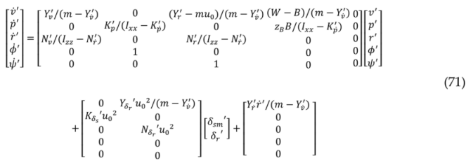
Horizontal plane dynamics include sway, roll, and yaw motions, as shown in (71).
Applsci 11 10978 i003
Using the models of (70) and (71), the PID controller is designed to control the roll, pitch, and yaw of the vehicle, respectively. The gains of each controller are designed to have a sufficient phase margin and gain margin using the pole-placement method of MATLAB’s SISOTOOL. We designed PID controllers for each of the p, q, r, ϕ, θ, and ψ directions. The phase margin of all controllers is designed to exceed at least 80 degrees, and the gain margin is also designed to exceed at least 30dB. However, since the linearized vehicle dynamics do not consider the influence of some non-linear terms, the PID controller can be vulnerable to disturbances.

4. Simulation

4.1. PID and SMCSPO Control Simulations without Disturbances

To compare and evaluate the performance of the PID and SMCSPO methods, the dynamics of the underwater vehicle and each control algorithms were implemented in MATLAB Simulink. Figure 2 shows a simplified control block diagram of an underwater vehicle. The reference input command of the system can be any other state variable except the surge direction variable among the state variables in (22). In this section, simulation results are only considered for the variables p ,   q , and r , which affect the high-speed turning of an underwater vehicle. The effect of disturbance on each controller is discussed in the next section.
In order to evaluate the high-speed turning performance of the vehicle according to the type of controller, the desired reference input is given as shown in Figure 3. The step reference input actually results in more velocity errors compared to a smooth curved trajectory; however, we used a step reference input to maximize turning velocity and acceleration. The shape of the desired reference input of p ,   q , and r is the same; however, the maximum desired angular velocity is different because of the limitation of the control fins δ r and δ s .
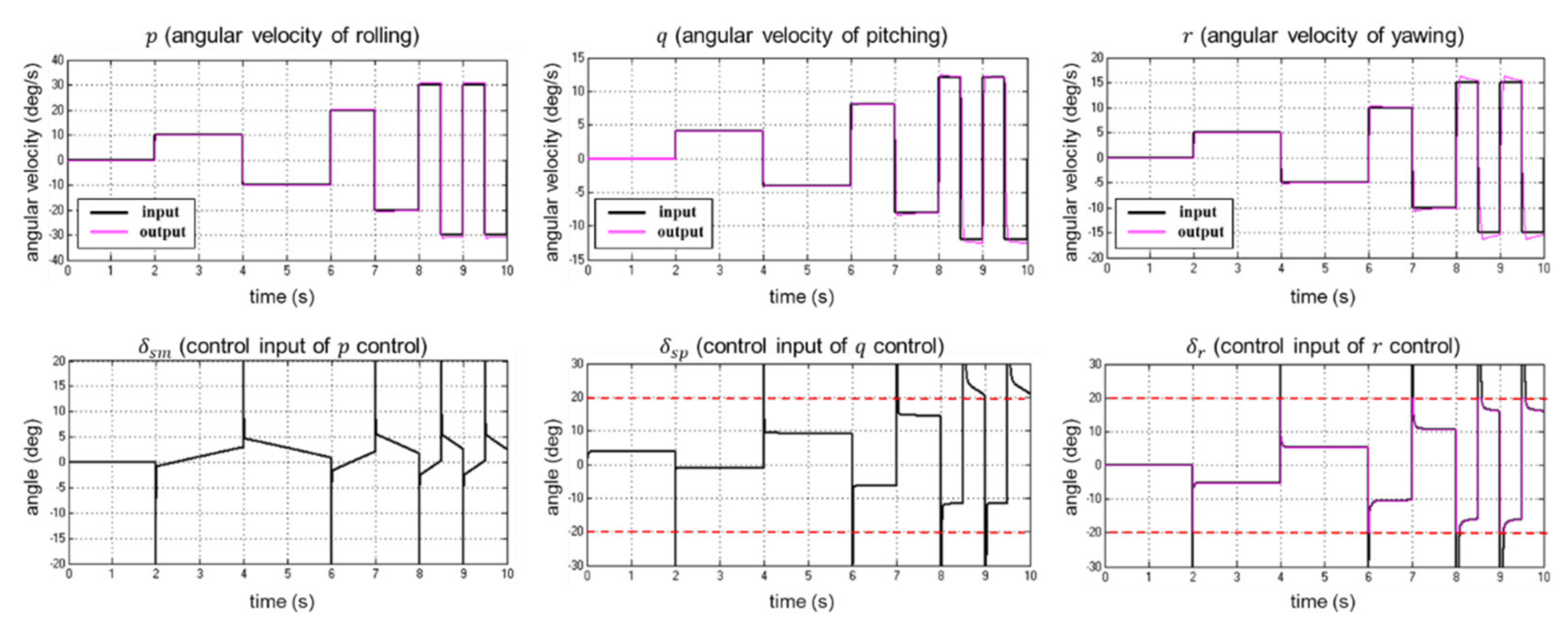
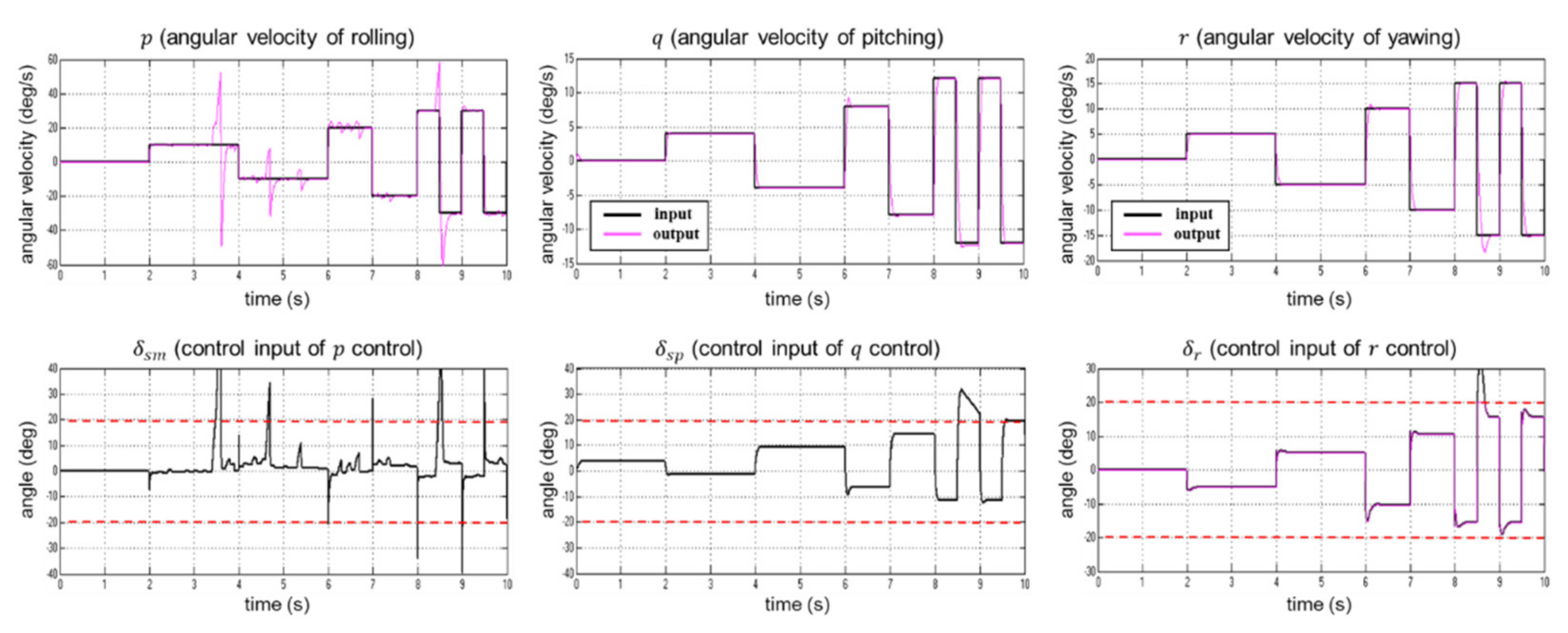
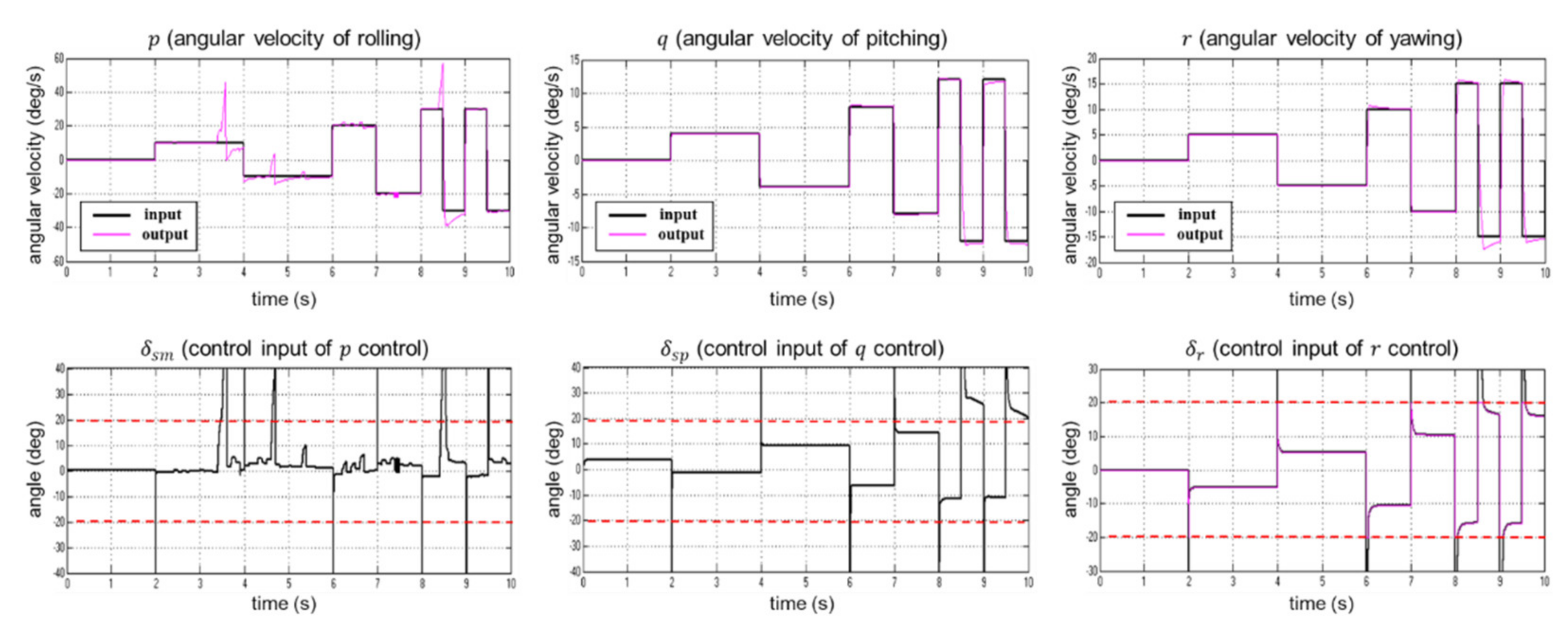
Figure 4 shows the PID control simulation results and control inputs of the vehicle’s rolling, pitching, and yawing velocity without any external disturbances, and Figure 5 shows SMCSPO control results. Red dotted lines on the control input graphs mean the angle limitation of control fins. In the rolling velocity control results of PID, it can be seen that there is an overshoot on the high-speed turning after 8 s of the simulation start point. On the other hand, in the rolling velocity simulation results of SMCSPO, the overshoot is significantly reduced in the same time section despite the high-speed turning of the vehicle. There are still some overshoots at t = 8.5 s and 9.5 s in the rolling velocity graph of SMCSPO; however, these are due to fin angle limitations of δ s m .
The SMC controller can robustly control the underwater vehicle; however, some chattering problems occur due to high switching gain in the control input. To solve this chattering problem, the SMCSPO controller is designed and applied to control the fin. Because SMCSPO can reduce the gain of the switching function term by compensating the estimated nonlinear terms, this chattering phenomenon in the control result using the SMCSPO is barely presented in Figure 5. Through the error graph of the vehicle’s rolling velocity in Figure 6, it is confirmed that the overall error of the SMCSPO controller is smaller than that of the PID controller.
In terms of the pitching and yawing velocity control results, the results for SMCSPO control also have some overshoots because of the control fin limitation. Due to the limited position of the control fins, the SMCSPO robust controller cannot provide sufficient control power to the vehicle system. These overshoots can be removed when the position limitations of the control fins are removed, as with the results of the rolling velocity control.

4.2. PID and SMCSPO Control Simulations with Disturbances

To compare the results of the vehicle’s PID and SMCSPO control in an underwater environment with disturbances, random disturbances were added to the disturbance part in Figure 2. In this simulation, two types of disturbances were considered: small and large. The small disturbance was a 10 Hz random signal with a variance of magnitude of 0.1 N 2 m 2 , and the large disturbance was also a 10 Hz random signal with a variance of magnitude of 10   N 2 m 2 . The reason for considering the random type of noise is that non-linear terms or sensor noise that are not modeled in the vehicle dynamics may be included in the underwater disturbance [2]. Therefore, we considered small, random, irregular disturbance within ±0.5 Nm in Figure 7 to compare with the PID control results. In addition, we used large, random, irregular disturbance within ±5 Nm to evaluate the control performance in a severe underwater environment. The small and large random disturbances are shown in Figure 7.
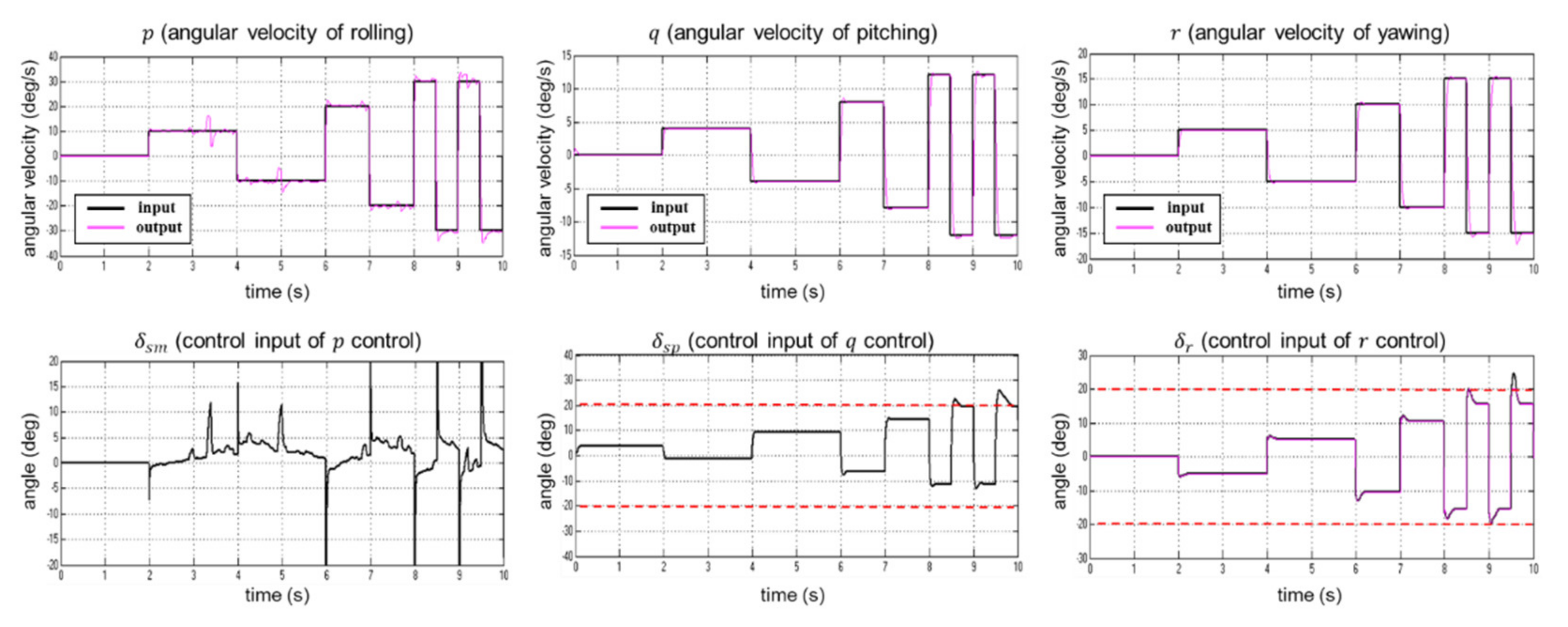
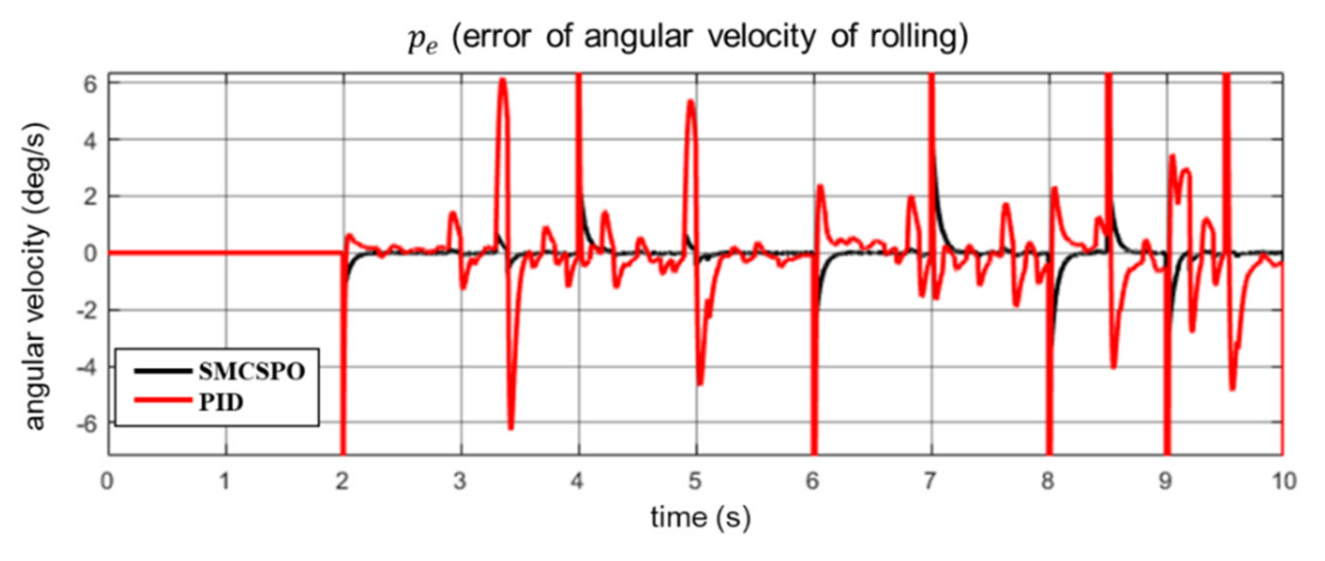
Figure 8 shows the PID control simulation results and control inputs of the vehicle’s rolling, pitching, and yawing velocity with small external disturbances, and Figure 9 shows the SMCSPO control results. The control input coefficient of rolling velocity K δ s has about a three times larger value than other control input coefficients M δ s and N δ r . In addition, the control fin angle of rolling velocity δ s m has an angle limitation that is twice as large as δ s p and δ r . Due to these characteristics of the underwater vehicle system, rolling velocity control is more vulnerable to disturbances compared to pitching and yawing velocity control. In the rolling control results of PID, it can be seen that the PID controller results in velocity errors of about ± 5 degrees even with a small disturbance. The SMCSPO control results are more robust to disturbance compared to the PID control results; the rolling control result of SMCSPO is hardly affected by small disturbances, as shown in Figure 9. Through the comparison of the rolling velocity’s error graphs of PID and SMCSPO in Figure 10, it is confirmed that the performance of SMCSPO is better than PID in a small disturbance environment.
Figure 11 shows the PID control simulation results and control inputs of the vehicle’s rolling, pitching, and yawing velocity with large external disturbances, and Figure 12 shows the SMCSPO control results. Although the SMCSPO control results of the rolling velocity are a little better than the PID control results, it was not possible to effectively suppress the effect of large disturbance because of the control fin limitation. However, in the case where the control input is smaller than the limit of the control fin in the 6–8 s section of the rolling velocity control graph in Figure 12, it can be seen that the SMCSPO control result is significantly better than the PID control result. In addition, despite the large magnitude of the strong disturbance, the vehicle’s control fins can be controlled stably using the SMCSPO controller, because there is almost no chattering phenomenon in the control input graph in Figure 12. In general, SMC performs better than PID control in nonlinear systems, but it has chattering problems [7]. The main difference between Figure 11 and Figure 12 is that SMCSPO results in almost no chattering, and thus it performs better than the PID control result.
Figure 13 shows the simulation results of rolling velocity when the control fin limit is set to a given default value and 1.5 times larger than that. If the angle limit of the control fin is large, it is confirmed that the effect due to disturbances, except for some strong disturbances, is well suppressed by the SMCSPO controller.

5. Conclusions

In this study, an SMCSPO controller is designed for the robust control of an underwater vehicle in an underwater disturbance environment. To evaluate the robustness of the SMCSPO control, a PID controller is also designed based on a linearized underwater vehicle model. The simulation results confirmed that the control results using the SMCSPO controller are overall better than the PID control result, especially in an underwater environment with small disturbances. When the vehicle is controlled in an environment with high disturbances, SMCSPO is not significantly better than PID due to the angle limitation of the control fins. The SMCSPO controller performed well when the vehicle could be controlled within the angle limit of the control fins. In addition, by estimating the nonlinear dynamics terms of the underwater vehicle using SPO, the gain of the SMC controller is reduced, and the vehicle could be controlled stably without chattering by SMCSPO.

Author Contributions

Conceptualization, H.-J.C. and J.-H.H.; methodology, M.C.L. and J.-S.W.; software, H.-H.K.; validation, H.-H.K. and M.C.L.; data curation, H.-H.K.; writing—original draft preparation, H.-H.K.; writing—review and editing, M.C.L.; supervision, H.-J.C. and J.-H.H.; project administration, H.-J.C. and J.-H.H.; All authors have read and agreed to the published version of the manuscript.

Funding

This research was supported by the Technology Innovation Program (10073147, Development of Robot Manipulation Technology by Using Artificial Intelligence) funded By the Ministry of Trade, Industry, and Energy (MOTIE, Korea), and the Agency for Defense Development, South Korea, under Grant UD150005DD, the Ministry of Trade, Industry, and Energy.

Institutional Review Board Statement

Not applicable.

Informed Consent Statement

Not applicable.

Data Availability Statement

The data presented in this study are openly available in follow link. https://drive.google.com/file/d/1I9CYthn4ihxf-pmt5vJRJCCm1gLGwVvK/view?usp=sharing (accessed on 18 November 2021).

Conflicts of Interest

The authors declare no conflict of interest.

References

  1. Feldman, J. Dtnsrdc Revised Standard Submarine Equations of Motion; David W. Taylor Naval Ship Research and Development Center: Bethesda, MD, USA, 1979. [Google Scholar]
  2. Prestero, T. Verification of a Six-Degree of Freedom Simulation Model for the REMUS Autonomous Underwater Vehicle. Ph.D. Thesis, Massachusetts Institute of Technology, Cambridge, MA, USA, 2001. [Google Scholar]
  3. Khan, I.; Bhatti, A.I.; Khan, Q.; Ahmad, Q. Sliding Mode Control of Lateral Dynamics of an AUV. In Proceedings of the 2012 9th International Bhurban Conference on Applied Sciences & Technology (IBCAST), Islamabad, Pakistan, 9–12 January 2012; pp. 28–31. [Google Scholar]
  4. Taheri, E.; Ferdowsi, M.H.; Danesh, M. Design Boundary Layer Thickness and Switching Gain in SMC Algorithm for AUV Motion Control. Robotica 2019, 37, 1785–1803. [Google Scholar] [CrossRef]
  5. Zhou, H.Y.; Liu, K.Z.; Feng, X.S. State Feedback Sliding Mode Control without Chattering by Constructing Hurwitz Matrix for AUV Movement. Int. J. Control Autom. Syst. 2011, 8, 262–268. [Google Scholar] [CrossRef] [Green Version]
  6. Yoerger, D.; Slotine, J. Robust Trajectory Control of Underwater Vehicles. IEEE JOE 1993, 10, 462–470. [Google Scholar]
  7. Moura, J.T.; Elmali, H.; Olgac, N. Sliding Mode Control with Sliding Perturbation Observer. J. Dyn. Syst. Meas. Cont. 1997, 119, 657–665. [Google Scholar] [CrossRef]
  8. Yoon, S.M.; Kim, W.J.; Lee, M.C. Design of Bilateral Control for Force Feedback in Surgical Robot. Int. J. Control Autom. Syst. 2015, 13, 916–925. [Google Scholar] [CrossRef]
  9. Rahman, N.; Lee, M.C. Actual Reaction Force Separation Method of Surgical Tool by Fuzzy Logic Based SMCSPO. Int. J. Control Autom. Syst. 2015, 13, 379–389. [Google Scholar] [CrossRef]
  10. Yoon, S.M.; Lee, M.C.; Kim, C.Y. Sliding Perturbation Observer Based Reaction Force Estimation Method of Surgical Robot Instrument for Haptic Realization. Int. J. Hum. Robot. 2015, 12, 1550013. [Google Scholar] [CrossRef]
  11. Kallu, K.D.; Wang, J.; Abbasi, S.J.; Lee, M.C. Estimated Reaction Force-Based Bilateral Control between 3DOF Master and Hydraulic Slave Manipulators for Dismantlement. Electronics 2018, 7, 256. [Google Scholar] [CrossRef] [Green Version]
  12. Wang, J.; Kallu, K.D.; Abbasi, S.J.; Lee, M.C. Trajectory Tracking Control of a Hydraulic System Using TSMCSPO based on Sliding Perturbation Observer. Appl. Sci. 2019, 9, 1455. [Google Scholar] [CrossRef] [Green Version]
  13. Kallu, K.D.; Abbasi, S.J.; Khan, H.; Wang, J.; Lee, M.C. Tele-Operated Bilateral Control of Hydraulic Manipulator Using a Robust Controller Based on the Sensorless Estimated Reaction Force. Appl. Sci. 2019, 9, 1995. [Google Scholar] [CrossRef] [Green Version]
  14. Kallu, K.D.; Abbasi, S.J.; Khan, H.; Wang, J.; Lee, M.C. Implementation of a TSMCSPO Controller on a 3DOF Hydraulic Manipulator for Position Tracking and Sensor-less Force Estimation. IEEE Access 2019, 7, 177035–177047. [Google Scholar] [CrossRef]
  15. Wang, J.; Zhou, Y.; Bao, Y.; Kim, H.H.; Lee, M.C. Trajectory Tracking Control Using Fractional-Order Terminal Sliding Mode Control with Sliding Perturbation Observer for a 7-DOF Robot Manipulator. IEEE/ASME Transact. Mechatron. 2020, 25, 1886–1893. [Google Scholar]
  16. Kim, H.H.; Lee, M.C.; Kyung, J.H.; Do, H.M. Evaluation of Force Estimation Method Based on Sliding Perturbation Observer for Dual-arm Robot System. Int. J. Control Autom. Syst. 2021, 19, 1–10. [Google Scholar] [CrossRef]
  17. Kim, H.H.; Kim, S.J.; Yoon, S.M.; Choi, Y.J.; Lee, M.C. Sliding Mode Control with Sliding Perturbation Observer-Based Strategy for Reducing Scratch Formation in Hot Rolling Process. Appl. Sci. 2021, 11, 5526. [Google Scholar] [CrossRef]
  18. Jeon, M.J.; Yoon, H.K.; Hwang, J.H.; Cho, H.J. Analysis of the dynamic characteristics for the change of design parameters of an underwater vehicle using sensitivity analysis. Int. J. Nav. Arch. Ocean Eng. 2018, 10, 508–519. [Google Scholar] [CrossRef]
  19. Elmali, H.; Olgac, N. Sliding mode control with perturbation estimation (SMCPE): A new approach. Int. J. Control 1992, 56, 923–941. [Google Scholar] [CrossRef]
Figure 1. Coordinate systems representation of AUV.
Applsci 11 10978 g001
Figure 2. Block diagram of underwater vehicle’s attitude and position control system.
Applsci 11 10978 g002
Figure 3. Desired reference angular velocity graphs of roll, pitch, yaw orientation.
Applsci 11 10978 g003
Figure 4. PID control simulation results without disturbances.
Applsci 11 10978 g004
Figure 5. SMCSPO control simulation results without disturbances.
Applsci 11 10978 g005
Figure 6. Rolling velocity’s error comparison of SMCSPO and PID controller without disturbances.
Applsci 11 10978 g006
Figure 7. Small and large disturbances.
Applsci 11 10978 g007
Figure 8. PID control simulation results with small disturbances (variance of magnitude = 0.1).
Applsci 11 10978 g008
Figure 9. SMCSPO control simulation results with small disturbances (variance of magnitude = 0.1).
Applsci 11 10978 g009
Figure 10. Rolling velocity’s error comparison of SMCSPO and PID controller with small disturbances (variance of magnitude = 0.1).
Applsci 11 10978 g010
Figure 11. PID control simulation results with large disturbances (variance of magnitude = 10).
Applsci 11 10978 g011
Figure 12. SMCSPO control simulation results with large disturbances (variance of magnitude = 10).
Applsci 11 10978 g012
Figure 13. Rolling velocity control result when the control fin limit is set to a given default value (a) and 1.5 times larger (b).
Applsci 11 10978 g013
Publisher’s Note: MDPI stays neutral with regard to jurisdictional claims in published maps and institutional affiliations.