
Assessment of Computer-Aided Design Tools for Topology Optimization of Additively Manufactured Automotive Components


Abstract
:1. Introduction
1.1. Topology Optimization Techniques
1.2. Topology Optimization Workflow
- TO1—Geometry preparation.
- TO2—Optimization setting.
- TO3—Results and Post-processing.
1.3. Topology Optimization Issues
- TO algorithms and tools and features development;
- TO workflow and DfAM effectiveness.
1.4. Need for Assessment Approaches to Select Design Tools
2. Assessment Approach
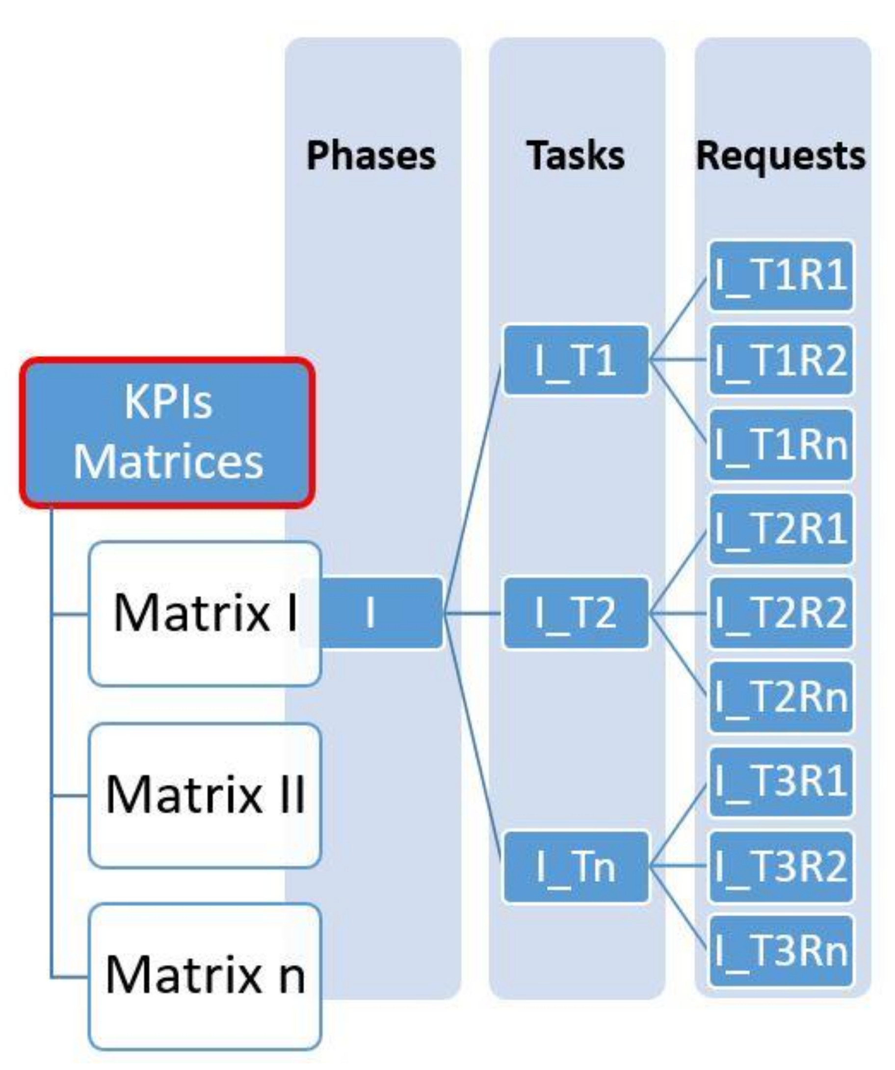
2.1. KPI Matrices Adoption
2.2. KPIs Matrices Structure
- I.
- Geometry preparation (GP);
- II.
- Optimization Setting (OS);
- III.
- Result and Post-processing (R&PP);
- IV.
- Interface and user experience (IT).
2.3. Overview of Requests Details
3. Case Study and Tools Systems Assessment
- The redesign project is defined and a simplified model is created;
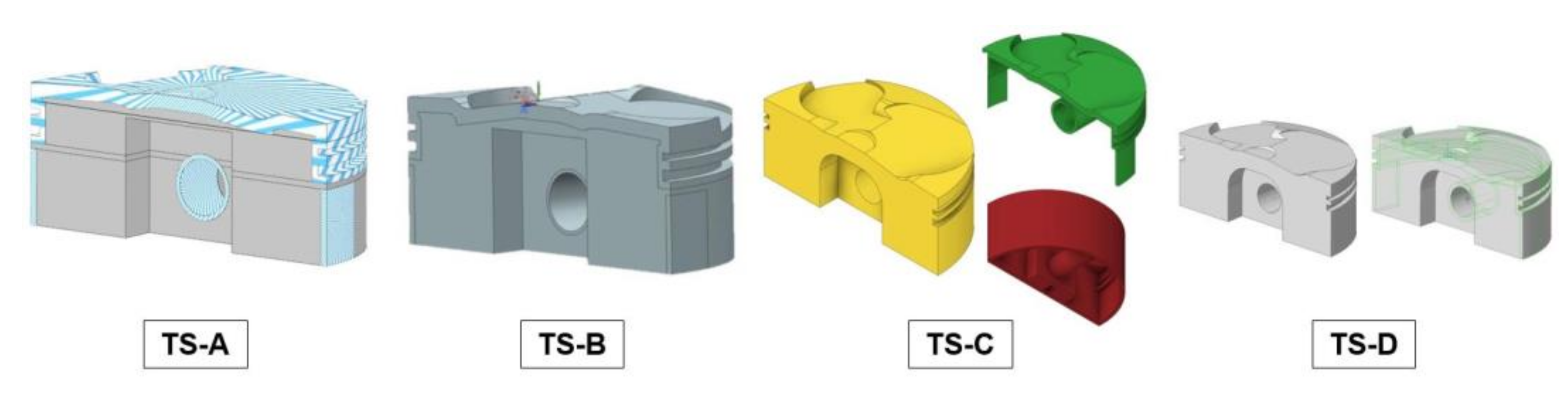
- The model is concurrently developed by means of four different TSs;
- The assessment method is applied for tools selection scope.
3.1. ICE Piston Redesign
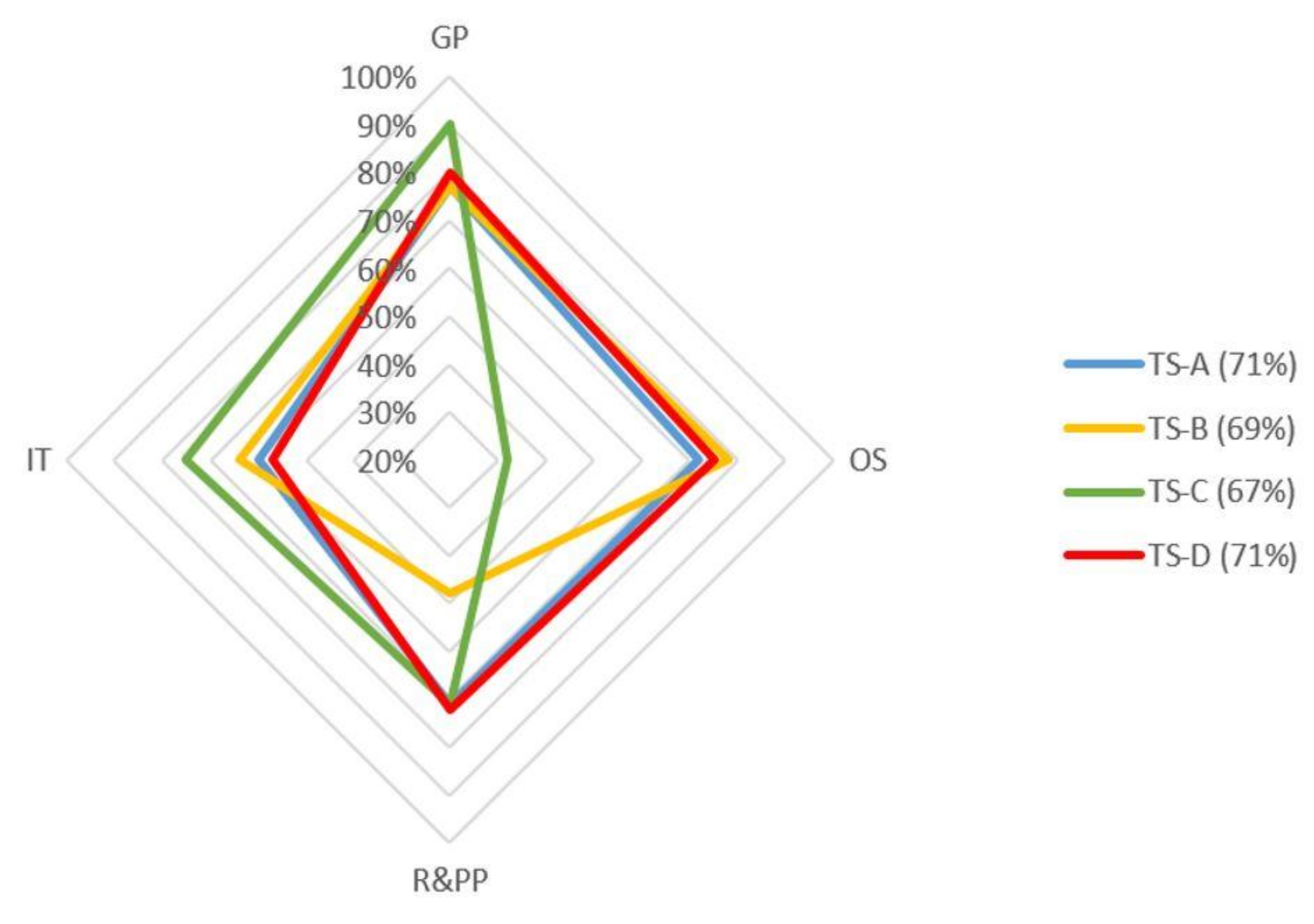
3.2. Tools System Selection
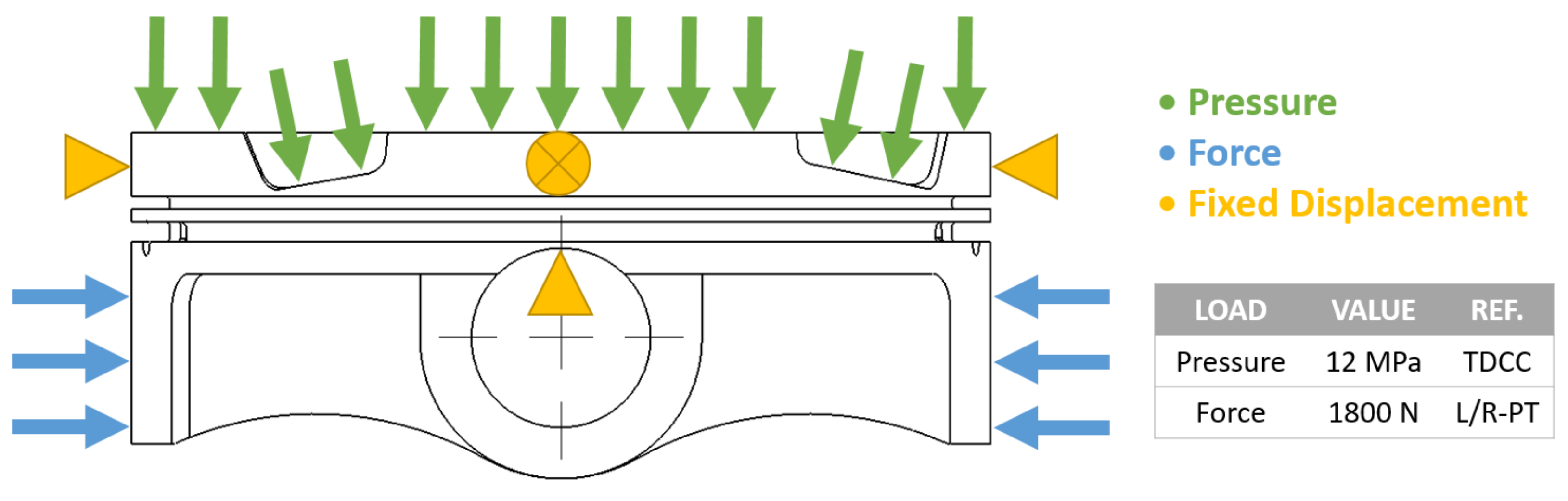
3.3. Topology Optimization
- Forces and pressures as structural loads;
- Fixed displacements as structural constraints;
- Half-geometry of the piston model.
- TO1—Geometry preparation.
- TO2—Optimization settings.
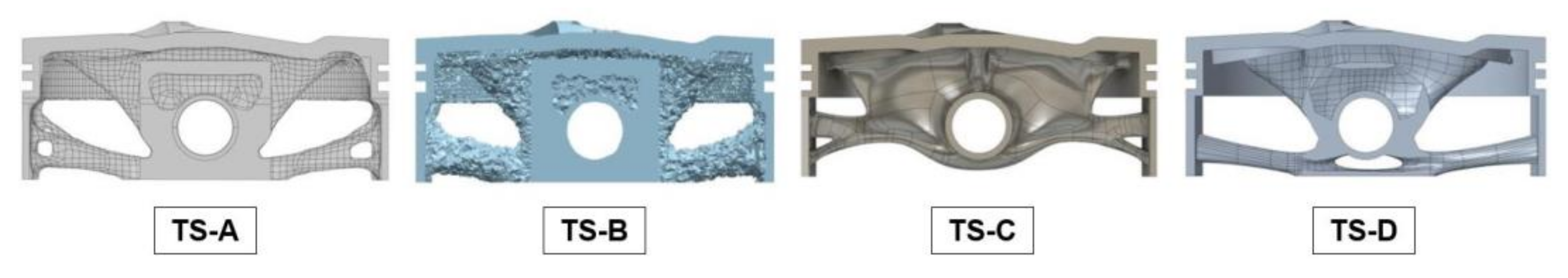
- TO3—Results and Post-processing.
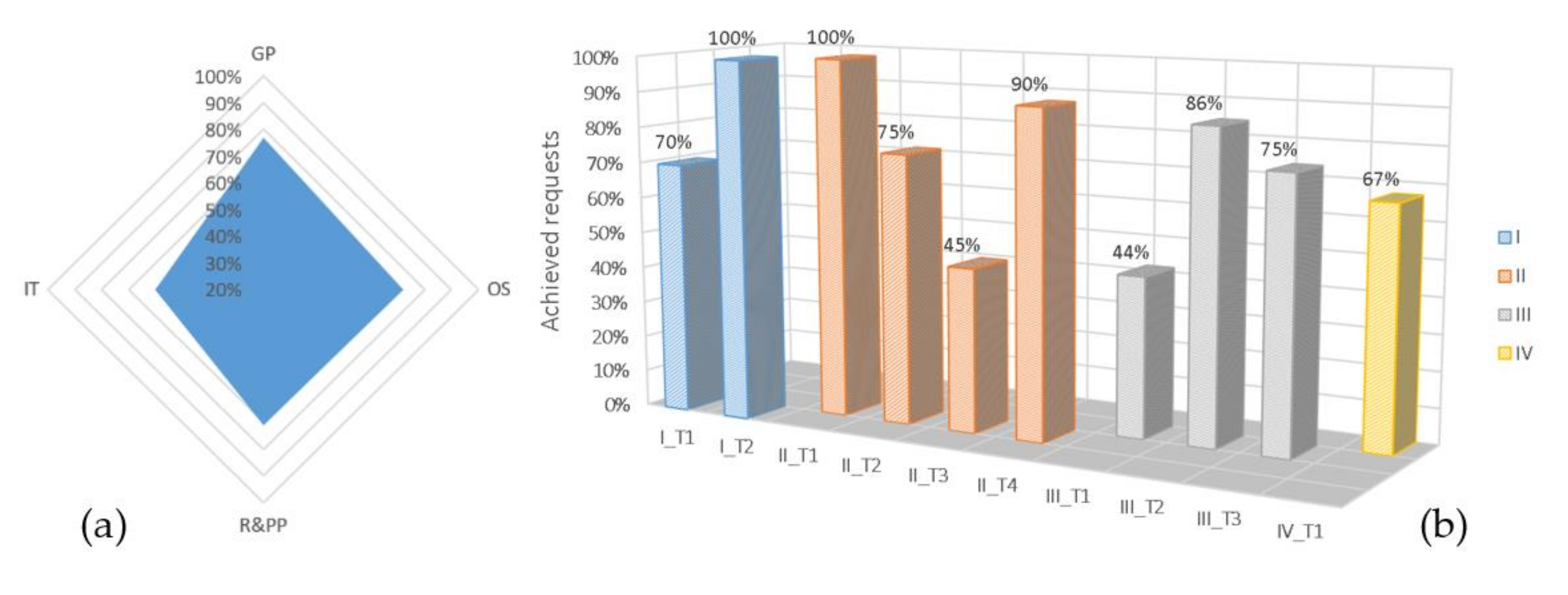
3.4. Assessment of Tools Systems
4. Results
5. Conclusions
Author Contributions
Funding
Acknowledgments
Conflicts of Interest
References
- Du Plessis, A.; Broeckhoven, C.; Yadroitsava, I.; Yadroitsev, I.; Hands, C.H.; Kunju, R.; Bhate, D. Beautiful and Functional: A Review of Biomimetic Design in Additive Manufacturing. Addit. Manuf. 2019, 27, 408–427. [Google Scholar] [CrossRef]
- Plocher, J.; Panesar, A. Review on Design and Structural Optimisation in Additive Manufacturing: Towards next-Generation Lightweight Structures. Mater. Des. 2019, 183, 108164. [Google Scholar] [CrossRef]
- Cavazzuti, M.; Baldini, A.; Bertocchi, E.; Costi, D.; Torricelli, E.; Moruzzi, P. High Performance Automotive Chassis Design: A Topology Optimization Based Approach. Struct. Multidiscip. Optim. 2011, 44, 45–56. [Google Scholar] [CrossRef]
- Brackett, D.; Ashcroft, I.; Hague, R. Topology Optimization for Additive Manufacturing 2011. In 22nd Annual International Solid Freeform Fabrication Symposium–An Additive Manufacturing Conference; University of Texas at Austin: Austin, TX, USA, 2011; pp. 348–362. [Google Scholar]
- Zegard, T.; Paulino, G.H. Bridging Topology Optimization and Additive Manufacturing. Struct. Multidiscip. Optim. 2016, 53, 175–192. [Google Scholar] [CrossRef]
- Meng, L.; Zhang, W.; Quan, D.; Shi, G.; Tang, L.; Hou, Y.; Breitkopf, P.; Zhu, J.; Gao, T. From Topology Optimization Design to Additive Manufacturing: Today’s Success and Tomorrow’s Roadmap. Arch. Comput. Methods Eng. 2020, 27, 805–830. [Google Scholar] [CrossRef]
- Rozvany, G.I.N. A Critical Review of Established Methods of Structural Topology Optimization. Struct. Multidiscip. Optim. 2009, 37, 217–237. [Google Scholar] [CrossRef]
- Bendsøe, M.P.; Kikuchi, N. Generating Optimal Topologies in Structural Design Using a Homogenization Method. Comput. Methods Appl. Mech. Eng. 1988, 71, 197–224. [Google Scholar] [CrossRef]
- Zuo, K.-T.; Chen, L.-P.; Zhang, Y.-Q.; Yang, J. Study of Key Algorithms in Topology Optimization. Int. J. Adv. Manuf. Technol. 2007, 32, 787–796. [Google Scholar] [CrossRef]
- Sigmund, O.; Maute, K. Topology Optimization Approaches. Struct. Multidiscip. Optim. 2013, 48, 1031–1055. [Google Scholar] [CrossRef]
- Reddy, S.N.; Ferguson, I.; Frecker, M.; Simpson, T.W.; Dickman, C.J. Topology Optimization Software for Additive Manufacturing: A Review of Current Capabilities and a Real-World Example. In Volume 2A: 42nd Design Automation Conference; American Society of Mechanical Engineers: Charlotte, NC, USA, 2016. [Google Scholar] [CrossRef]
- Gardan, N.; Schneider, A.; Gardan, J. Material and Process Characterization for Coupling Topological Optimization to Additive Manufacturing. Comput. -Aided Des. Appl. 2016, 13, 39–49. [Google Scholar] [CrossRef]
- Liu, J.; Gaynor, A.T.; Chen, S.; Kang, Z.; Suresh, K.; Takezawa, A.; Li, L.; Kato, J.; Tang, J.; Wang, C.C.L.; et al. Current and Future Trends in Topology Optimization for Additive Manufacturing. Struct. Multidiscip. Optim. 2018, 57, 2457–2483. [Google Scholar] [CrossRef] [Green Version]
- Zuo, K.-T.; Chen, L.-P.; Zhang, Y.-Q. Manufacturing- and Machining-Based Topology Optimization. Int. J. Adv. Manuf. Technol. 2006, 27, 531–536. [Google Scholar] [CrossRef]
- Harzheim, L.; Graf, G. A Review of Optimization of Cast Parts Using Topology Optimization. Struct. Multidiscip. Optim. 2006, 31, 388–399. [Google Scholar] [CrossRef]
- Dalpadulo, E.; Pini, F.; Leali, F. Integrated CAD Platform Approach for Design for Additive Manufacturing of High Performance Automotive Components. Int. J. Interact. Des. Manuf. (IJIDeM) 2020, 14, 899–909. [Google Scholar] [CrossRef]
- Gaynor, A.T.; Guest, J.K. Topology Optimization for Additive Manufacturing: Considering Maximum Overhang Constraint. In 15th AIAA/ISSMO Multidisciplinary Analysis and Optimization Conference; American Institute of Aeronautics and Astronautics: Reston, VI, USA, 2014. [Google Scholar] [CrossRef]
- Leary, M.; Merli, L.; Torti, F.; Mazur, M.; Brandt, M. Optimal Topology for Additive Manufacture: A Method for Enabling Additive Manufacture of Support-Free Optimal Structures. Mater. Des. 2014, 63, 678–690. [Google Scholar] [CrossRef]
- Mezzadri, F.; Bouriakov, V.; Qian, X. Topology Optimization of Self-Supporting Support Structures for Additive Manufacturing. Addit. Manuf. 2018, 21, 666–682. [Google Scholar] [CrossRef]
- Langelaar, M. Combined Optimization of Part Topology, Support Structure Layout and Build Orientation for Additive Manufacturing. Struct. Multidiscip. Optim. 2018, 57, 1985–2004. [Google Scholar] [CrossRef] [Green Version]
- Mirzendehdel, A.M.; Suresh, K. Support Structure Constrained Topology Optimization for Additive Manufacturing. Comput. -Aided Des. 2016, 81, 1–13. [Google Scholar] [CrossRef] [Green Version]
- Allaire, G.; Dapogny, C.; Estevez, R.; Faure, A.; Michailidis, G. Structural Optimization under Overhang Constraints Imposed by Additive Manufacturing Technologies. J. Comput. Phys. 2017, 351, 295–328. [Google Scholar] [CrossRef] [Green Version]
- Hoffarth, M.; Gerzen, N.; Pedersen, C. ALM Overhang Constraint in Topology Optimization for Industrial Applications. In 12th World Congress on Structural and Multidisciplinary Optimisation; Springer: Braunschweig, Germany, 2017; pp. 1–11. [Google Scholar]
- Zhang, P.; Liu, J.; To, A.C. Role of Anisotropic Properties on Topology Optimization of Additive Manufactured Load Bearing Structures. Scr. Mater. 2017, 135, 148–152. [Google Scholar] [CrossRef]
- Cheng, L.; Bai, J.; To, A.C. Functionally Graded Lattice Structure Topology Optimization for the Design of Additive Manufactured Components with Stress Constraints. Comput. Methods Appl. Mech. Eng. 2019, 344, 334–359. [Google Scholar] [CrossRef]
- Dong, G.; Tang, Y.; Li, D.; Zhao, Y.F. Design and optimization of solid lattice hybrid structures fabricated by additive manufacturing. Addit. Manuf. 2020, 33, 101116. [Google Scholar] [CrossRef]
- Zhu, J.; Zhou, H.; Wang, C.; Zhou, L.; Yuan, S.; Zhang, W. A Review of Topology Optimization for Additive Manufacturing: Status and Challenges. Chin. J. Aeronaut. 2021, 34, 91–110. [Google Scholar] [CrossRef]
- Dalpadulo, E.; Pini, F.; Leali, F. Assessment of Design for Additive Manufacturing Based on CAD Platforms. Lect. Notes Mech. Eng. 2020, 970–981. [Google Scholar] [CrossRef]
- Lindemann, C.; Reiher, T.; Jahnke, U.; Koch, R. Towards a Sustainable and Economic Selection of Part Candidates for Additive Manufacturing. Rapid Prototyp. J. 2015, 21, 216–227. [Google Scholar] [CrossRef]
- Wiberg, A.; Persson, J.; Ölvander, J. Design for Additive Manufacturing–A Review of Available Design Methods and Software. Rapid Prototyp. J. 2019, 25, 1080–1094. [Google Scholar] [CrossRef] [Green Version]
- Reddy, S.N.; Maranan, V.; Simpson, T.W.; Palmer, T.; Dickman, C.J. Application of Topology Optimization and Design for Additive Manufacturing Guidelines on an Automotive Component. In Volume 2A: 42nd Design Automation Conference; American Society of Mechanical Engineers: Charlotte, NC, USA, 2016. [Google Scholar] [CrossRef]
- Dalpadulo, E.; Pini, F.; Leali, F. Components residual stress and deformation reduction: An integrated process design for additive manufacturing. In International Mechanical Engineering Congress and Exposition (IMECE); Virtual Conference: New York, NY, USA, 2021. [Google Scholar]
- Saadlaoui, Y.; Milan, J.L.; Rossi, J.M.; Chabrand, P. Topology Optimization and Additive Manufacturing: Comparison of Conception Methods Using Industrial Codes. J. Manuf. Syst. 2017, 43, 178–186. [Google Scholar] [CrossRef]
- Dalpadulo, E.; Pini, F.; Leali, F. Systematic Integration of Topology Optimization Techniques in Design for Additive Manufacturing Methodologies Applied to Automotive Settings. In International Mechanical Engineering Congress and Exposition (IMECE); Virtual Conference: Portland, OR, USA, 2020. [Google Scholar] [CrossRef]
- Fumagalli, L.; Polenghi, A.; Negri, E.; Roda, I. Framework for Simulation Software Selection. J. Simul. 2019, 13, 286–303. [Google Scholar] [CrossRef]
- Alomair, Y.; Ahmad, I.; Alghamdi, A. A Review of Evaluation Methods and Techniques for Simulation Packages. Procedia Comput. Sci. 2015, 62, 249–256. [Google Scholar] [CrossRef] [Green Version]
- The 3DEXPERIENCE Platform, a Game Changer for Business and Innovation. Available online: https://www.3ds.com/3dexperience (accessed on 8 November 2021).
- NX Cloud Connected Products Offer the Next Generation of Flexibility for Product Design. Available online: https://www.plm.automation.siemens.com/global/en/products/nx/ (accessed on 8 November 2021).
- Fusion 360. Integrated CAD, CAM, CAE, and PCB Software. Available online: https://www.autodesk.com/products/fusion-360/overview (accessed on 8 November 2021).
- Creo: Design. The Way It Should Be. Available online: https://www.ptc.com/en/products/creo (accessed on 8 November 2021).


| Abbreviation | Definition |
|---|---|
| AM | Additive Manufacturing |
| TO | Topology Optimization |
| DfAM | Design for Additive Manufacturing |
| KPI | Key Performance Indicator |
| TS | Tools System |
| GP | Geometry Preparation |
| OS | Optimization Setting |
| R&PP | Results and Post-Processing |
| IT | Interface and user experience |
| Phase | Task | Request | Description | Code | Status | More Details |
|---|---|---|---|---|---|---|
| I | I_T1 | Is it possible to import an STL file? | While importing a file in the CAD model environment, the .stl extension should be among the options | I_T1R1 | Yes |
| I. Geometry Preparation | |
| Task | Requests |
| Design space and Non-Design space definition | file import, geometry modification, features management, design areas for different bodies, surfaces or volumes splitting, features for non-design areas creation, regions with special structures (e.g., latticing, cellular structures etc.) |
| Material definition | material editing, material anisotropy, temperature dependent data for thermal simulations. |
| II. Optimization Setting | |
| Task | Requests |
| Mesh creation | element type, mesh element size, several meshes, mesh properties control, mesh quality check, mesh quality improving, elements and nodes numbering, mesh configuration save/reuse, rigid elements creation. |
| Loadcases definition | thermal loads, connections, loads/restraints support type, load distribution/spatial variation, association by sets, multiple loadcases, preliminary structural analysis, analysis type selection, model check. |
| Optimization setup | different design objectives, multiple objectives, design constraints, multiple design constraints, shape constraints, manufacturing constraints, AM constraints, printing direction, min/max structure size, filling structures, optimization algorithm parameters setting. |
| Solving and errors | error display, error explanation, problem cause tracing, computation parameters setting, CPU usage set, computation history along cycles, time needed to perform cycles, computing duration estimation, optimization report, working while optimization is running. |
| III. Results and Post Processing | |
| Task | Requests |
| Results display | result preview, relative density adjustment, result mass check, result of each cycle, cycle-result exploitation, result data visualization, shapes comparison, result of design objective, data in case of failure. |
| Geometry generation | generating geometry, density threshold setting, geometry shape improvement, overhang control preservation, mass target deviation, geometries and data comparison, geometry update by editing initial model. |
| Post-processing | generated geometry modification, ready to print possibility, overhanging features display, shape analysis, generated geometry simulation, TO information retrieving, final geometry export, export formats. |
| IV. Interface | |
| Task | Requests |
| Input data and workflow | feature tree along setup, input data edition on tree, summary of input data, editing data by summary, driven optimization, assistive toolbar, missing step/not complete warning, cloud data storage, workspace customization. |
| Phase | GP | OS | R&PP | IT | Total |
|---|---|---|---|---|---|
| Investigated Requests | 13 | 46 | 24 | 10 | 93 |
| Achieved Requests | 10 | 33 | 17 | 6 | 66 |
| AR% | 77% | 72% | 71% | 60% | 71% |
Publisher’s Note: MDPI stays neutral with regard to jurisdictional claims in published maps and institutional affiliations. |
© 2021 by the authors. Licensee MDPI, Basel, Switzerland. This article is an open access article distributed under the terms and conditions of the Creative Commons Attribution (CC BY) license (https://creativecommons.org/licenses/by/4.0/).
Share and Cite
Dalpadulo, E.; Pini, F.; Leali, F. Assessment of Computer-Aided Design Tools for Topology Optimization of Additively Manufactured Automotive Components. Appl. Sci. 2021, 11, 10980. https://doi.org/10.3390/app112210980
Dalpadulo E, Pini F, Leali F. Assessment of Computer-Aided Design Tools for Topology Optimization of Additively Manufactured Automotive Components. Applied Sciences. 2021; 11(22):10980. https://doi.org/10.3390/app112210980
Chicago/Turabian StyleDalpadulo, Enrico, Fabio Pini, and Francesco Leali. 2021. "Assessment of Computer-Aided Design Tools for Topology Optimization of Additively Manufactured Automotive Components" Applied Sciences 11, no. 22: 10980. https://doi.org/10.3390/app112210980
APA StyleDalpadulo, E., Pini, F., & Leali, F. (2021). Assessment of Computer-Aided Design Tools for Topology Optimization of Additively Manufactured Automotive Components. Applied Sciences, 11(22), 10980. https://doi.org/10.3390/app112210980