
Nonlinear Optimal Position Control with Observer for Position Tracking of Surfaced Mounded Permanent Magnet Synchronous Motors


Abstract
:1. Introduction
2. Model and Review of Classical Control Methods
2.1. Mathematical Model of Surface Mounted PMSM Motor
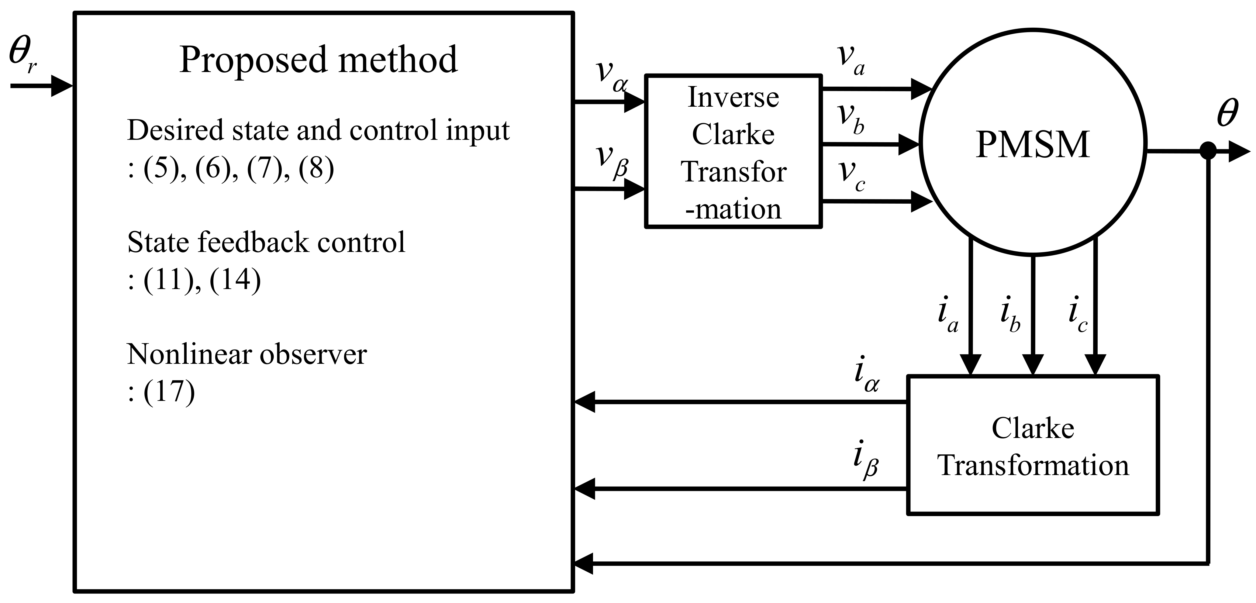
2.2. Review of Control Method Using DQ Transformation
3. Position Tracking Controller Design
3.1. Desired State Design
3.2. Controller Design
3.3. Control Gain Selection Using Optimal Control
3.4. Nonlinear Observer
3.5. Observer Gain Selection Using Optimal Control
3.6. Closed-Loop System Stability Analysis
4. Simulation and Experimental Results
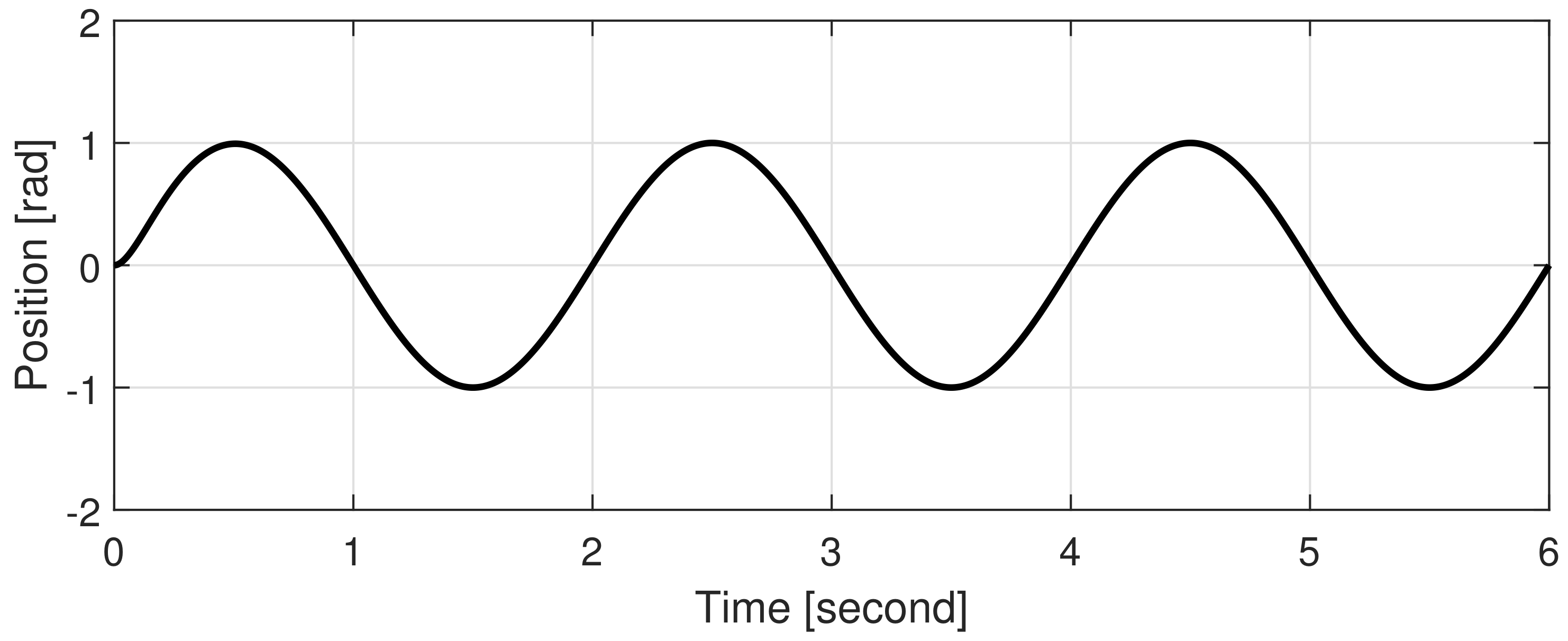
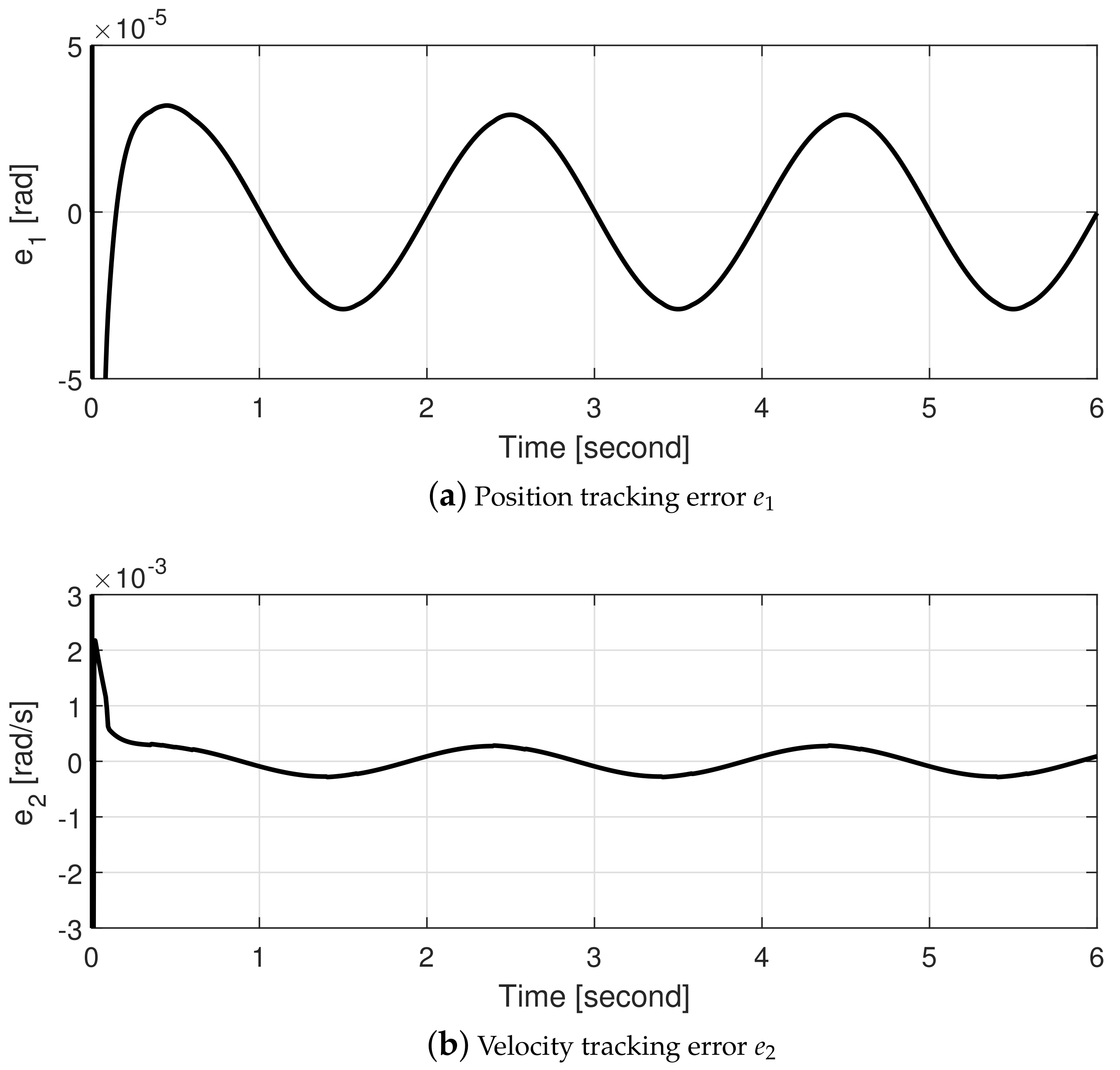
4.1. Simulations
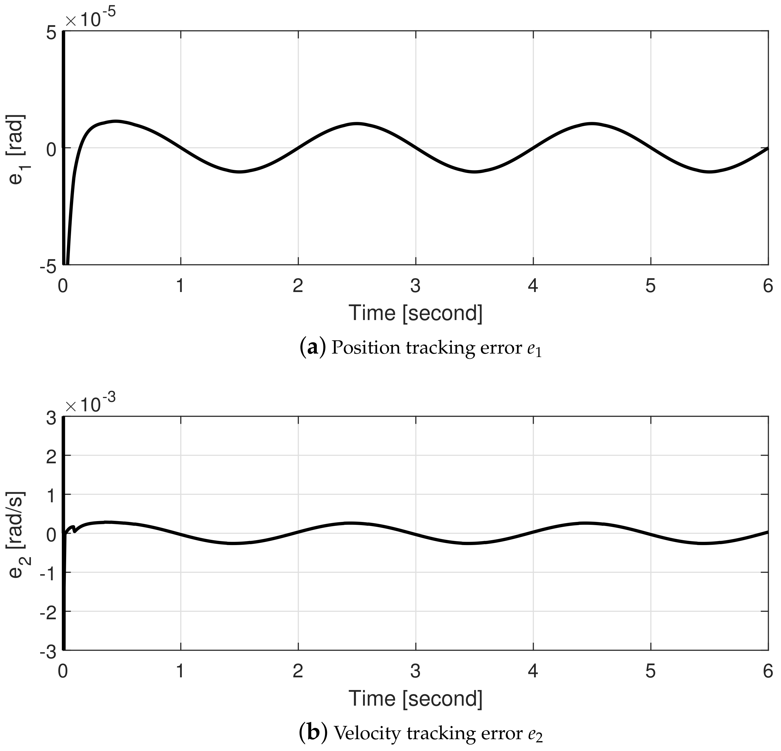
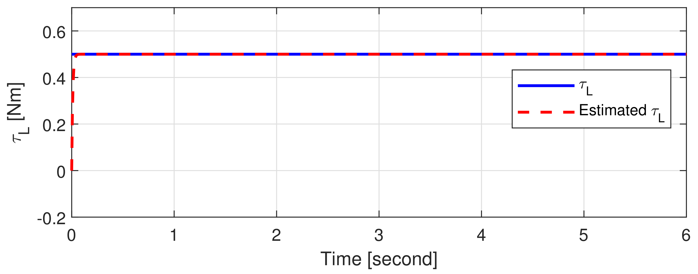
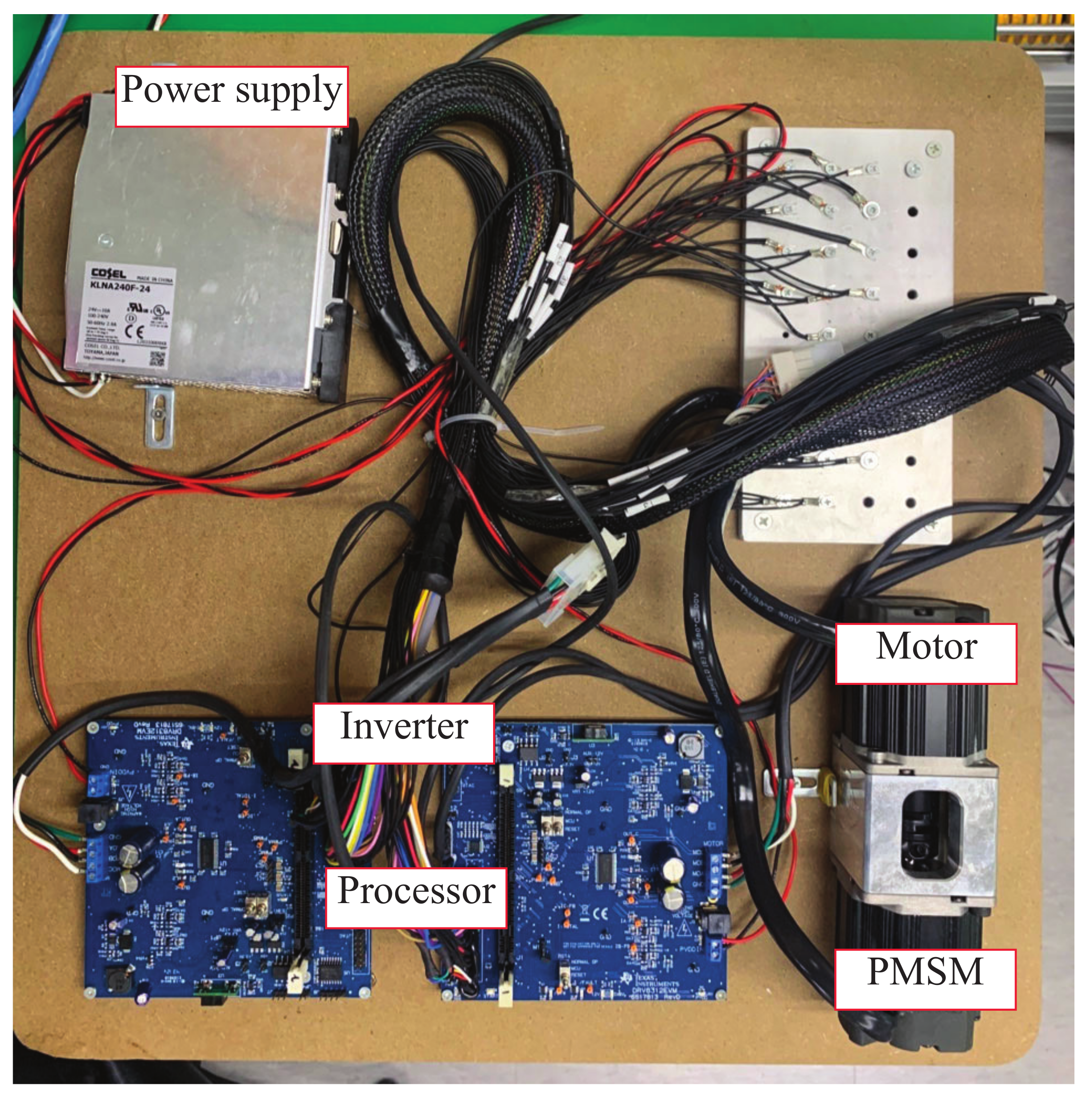
4.2. Experiments
5. Conclusions
Author Contributions
Funding
Institutional Review Board Statement
Informed Consent Statement
Data Availability Statement
Conflicts of Interest
References
- Bose, B.K. Power Electronics and AC Drives; Prentice-Hall: Englewood Cliffs, NJ, USA, 1968. [Google Scholar]
- Toliyat, H.A.; Kliman, G.B. Handbook of Electric Motors; Marcel Dekker: New York, NY, USA, 2004. [Google Scholar]
- Hur, J. Characteristic analysis of interior permanent-magnet synchronous motor in electrohydraulic power steering systems. IEEE Trans. Ind. Electon. 2008, 55, 2316–2323. [Google Scholar]
- Tursini, M.; Parasiliti, F.; Zhang, D. Real-time gain tuning of PI controllers for high-performance PMSM drives. IEEE Trans. Ind. Appl. 2002, 38, 1018–1026. [Google Scholar] [CrossRef]
- GrCar, B.; Cafuta, P.; Znidaric, M.; Gausch, F. Nonlinear Control of Synchronous Servo Drive. IEEE Trans. Control Syst. Technol. 1996, 4, 177–184. [Google Scholar] [CrossRef]
- Baik, I.-C.; Kim, K.-H.; Youn, M.-J. Robust nonlinear speed control of PM synchronous motor using boundary layer integral sliding mode control technique. IEEE Trans. Control Syst. Technol. 2000, 8, 47–54. [Google Scholar] [CrossRef]
- Chung, M.-J.; Gweon, D.-G. Design optimization and development of linear brushless permanent magnet motor. Int. J. Control. Automa. Syst. 2003, 1, 351–357. [Google Scholar]
- Hernandez-Guzman, V.M.; Silva-Ortigoza, R. PI control plus electric current loops for PM synchronous motors. IEEE Trans. Control Syst. Technol. 2011, 19, 868–873. [Google Scholar] [CrossRef]
- Li, S.; Zong, K.; Liu, H. A composite speed controller based on a second-order model of permanent magnet synchronous motor system. Trans. Insttute Meas. Control 2011, 33, 522–541. [Google Scholar]
- Zhang, X.; Zhang, L.; Zhang, Y. Model predictive current control for PMSM drives with parameter robustness improvement. IEEE Trans. Power Electron. 2018, 34, 1645–1657. [Google Scholar] [CrossRef]
- Du, H.; Wen, G.; Cheng, Y.; Lu, J. Design and implementation of bounded finite-time control algorithm for speed regulation of permanent magnet synchronous motor. IEEE Trans. Ind. Electron. 2021, 68, 2417–2426. [Google Scholar] [CrossRef]
- Le, K.M.; Hoang, H.V.; Jeon, J.W. An advanced closed-loop control to improve the performance of hybrid steppermotors. IEEE Trans. Power Electron. 2017, 32, 7244–7255. [Google Scholar] [CrossRef]
- Zhou, Z.; Xia, C.; Yan, Y.; Wang, Z.; Shi, T. Disturbances attenuation of permanent magnet synchronous motor drives using cascaded predictive integral-resonant controllers. IEEE Trans. Power Electron. 2018, 33, 1514–1527. [Google Scholar] [CrossRef]
- Lee, Y.; Gil, J.; Kim, W. Velocity control for sideband harmonics compensation in permanent magnet synchronous motors with low switching frequency inverter. IEEE Trans. Ind. Electron. 2021, 68, 3434–3444. [Google Scholar] [CrossRef]
- Zhu, W.; Chen, D.; Du, H.; Wang, X. Position control for permanent magnet synchronous motor based on neural network and terminal sliding mode control. Trans. Inst. Meas. Control 2020, 42, 1632–1640. [Google Scholar] [CrossRef]
- Xia, C.; Liu, N.; Zhou, Z.; Yan, Y.; Shi, T. Steady-state performance improvement for LQR-based PMSM drives. IEEE Trans. Power Electron. 2018, 33, 10622–10632. [Google Scholar] [CrossRef]
- Alfehaid, A.A.; Strangas, E.G.; Khalil, H.K. Speed control of permanent magnet synchronous motor with uncertain parameters and unknown disturbance. IEEE Trans. Control Syst. Technol. 2021, 29, 2639–2646. [Google Scholar] [CrossRef]
- Kim, W.; Shin, D.; Chung, C.C. The Lyapunov-based controller with a passive nonlinear observer to improve position tracking performance of microstepping in permanent magnet stepper motors. Automatica 2012, 48, 3064–3074. [Google Scholar] [CrossRef]
- Ortega, R.; Praly, L.; Astolfi, A.; Lee, J.; Nam, K. Estimation of rotor position and speed of permanent magnet synchronous motors with guaranteed stability. IEEE Trans. Control Syst. Technol. 2010, 19, 601–614. [Google Scholar] [CrossRef]
- Pauline, B.; Praly, L. Convergence of gradient observer for rotor position and magnet flux estimation of permanent magnet synchronous motors. Automatica 2018, 94, 88–93. [Google Scholar]
- Pyrkin, A.; Bobtsov, A.; Ortega, R.; Vedyakov, A.; Cherginets, D.; Ovcharov, A.; Bazylev, D.; Petranevsky, I. Robust nonlinear observer design for permanent magnet synchronous motors. IET Control Theory Appl. 2021, 15, 604–616. [Google Scholar] [CrossRef]
- Park, R.H. Two-reaction theory of synchronous machines generalized method of analysis. AIEE Trans. 1929, 48, 716–727. [Google Scholar] [CrossRef]
- Krishnamurthy, P.; Khorrami, F. An analysis of the effects of closed-loop commutation delay on stepper motor control and application to parameter estimation. IEEE Trans. Control Syst. Technol. 2008, 16, 70–77. [Google Scholar] [CrossRef]
- Åström, K.J.; Hägglund, T. The future of PID control. Control engineering practice. Control Eng. Prac. 2001, 9, 1163–1175. [Google Scholar] [CrossRef]
- Shin, D.; Kim, W.; Chung, C.C. Position control of a permanent magnet stepper motor by MISO backstepping in semi-strict feedback form. In Proceedings of the 2011 IEEE/ASME International Conference on Advanced Intelligent Mechatronics (AIM), Budapest, Hungary, 3–7 July 2011; pp. 808–813. [Google Scholar]


| Para. | Value | Para. | Value |
|---|---|---|---|
| L | 11 mH | R | |
| 0.18 V·s/rad | J | 0.006 Kg·m | |
| p | 3 | B | 0.001 N·m· s/rad |
Publisher’s Note: MDPI stays neutral with regard to jurisdictional claims in published maps and institutional affiliations. |
© 2021 by the authors. Licensee MDPI, Basel, Switzerland. This article is an open access article distributed under the terms and conditions of the Creative Commons Attribution (CC BY) license (https://creativecommons.org/licenses/by/4.0/).
Share and Cite
Ha, D.H.; Kim, R. Nonlinear Optimal Position Control with Observer for Position Tracking of Surfaced Mounded Permanent Magnet Synchronous Motors. Appl. Sci. 2021, 11, 10992. https://doi.org/10.3390/app112210992
Ha DH, Kim R. Nonlinear Optimal Position Control with Observer for Position Tracking of Surfaced Mounded Permanent Magnet Synchronous Motors. Applied Sciences. 2021; 11(22):10992. https://doi.org/10.3390/app112210992
Chicago/Turabian StyleHa, Dong Hyun, and Raeyoung Kim. 2021. "Nonlinear Optimal Position Control with Observer for Position Tracking of Surfaced Mounded Permanent Magnet Synchronous Motors" Applied Sciences 11, no. 22: 10992. https://doi.org/10.3390/app112210992