2.1. Literature Review
As VR contents are increasingly used in many applications, research on the creation and processing of the contents is also growing. In addition, 360-degree image and video acquisition sensors are now easily accessible for consumers, which has gained the attention of researchers for use in generating high-quality images.
Duan et al. [
18] introduced an interesting study generating panoramas from a two-dimensional sketch and proposed a spherical generative adversarial network (GAN) system for stitching. The sketch, a concise geometric structure comprising about 7% of the panoramic image, created a high-fidelity spherical image. Bertel et al. [
19] introduced a compact approach to capture high-quality omnidirectional panorama images with motion parallax. They captured a 360-degree video using a handheld 360-degree video camera with a selfie stick by rotating it for 3 or 10 s. They improved the visual quality by improving the vertical distortion using deformable proxy geometry. Akimoto et al. [
20] proposed a GANs network to stitch a 360-degree image from its parts. They used a two-stage approach with series-parallel dilated convolution layers. The result showed many distortions in the output 360-degree image, as their approach is the initial step to generate a 360-degree image from an unseen area input. Similarly, H. Ullah et al. [
21] focused on cost effectiveness and proposed a low-cost mono and stereo panorama automatic stitching system. For a mono omnidirectional image, they presented a sensor kit mounted on a drone consisting of six cameras. For a stereo omnidirectional image, they proposed a cost-effective visual sensor kit consisting of three cameras. For both systems, they developed their own stitching software to achieve a good-quality image from both the objective and subjective perspective. Berenguel-Baeta et al. [
22] presented a tool to create omnidirectional, synthetic, and photorealistic images in various projection formats such as equirectangular, cylindrical, dioptric, and equiangular with labeled information. The tool supports the generation of datasets with depth and semantic information of the panoramas. These panoramas are synthesized from a set of captures in a realistic virtual environment. Their depth and semantic information can be used to train learning algorithms and test 3D vision approaches.
Parallel with the generation of panoramic contents, the processing of such content has also drawn great attention. Researchers and developers process such content for different purposes. Duanmu et al. [
23] investigated the behavior of users while watching 360-degree videos and proposed a novel dataset of users’ trajectories. They captured the viewing trajectories of users using twelve 360-degree videos recorded on computers/laptops and compared these computer-based trajectories with the existing head-mounted device (HMD). It is stated that users have almost the same behavior and navigation when wearing an HMD as when they watch 360-degree videos. Zhang et al. [
24] studied a quality enhancement of 360-degree images using deep neural networks based on GANs without changing the image resolution. They designed a compact network employing a multi-frequency structure with compressed Residual-in-Residual Dense Blocks and convolution layers from each dense block. Zhu et al. [
25] proposed a saliency predictor for panoramas to improve the perceptual experience of the viewer by predicting head and eye movements. They extracted features at different frequency bands and orientations using spherical harmonics in the spherical domain and used these features to predict head and eye movements and estimate the saliency. Adhuran et al. [
26] researched coding efficiency. They used the features of weighted Craster parabolic projection PSNR and proposed an algorithm for residual weighting to reduce the residual magnitude for 360-degree video compression. They also proposed a quantization parameter for optimization, which was used to reduce the residuals’ magnitude reduction. They improved coding efficiency by 3.34% on average.
Some researchers also worked to improve VR contents’ quality assessment. To assess the visual quality of the VR image, Kim et al. [
27] proposed a VR quality score predictor and human perception guider based on deep-learning methods. They encoded positional and visual information regarding patches to obtain weight and quality scores. They predicted the overall image quality score by aggregating the quality score of patches with a respective weight of patches. Orduna et al. [
28] used a full-reference video quality assessment metric: Video Multimethod Assessment Fusion (VMAF) for 360-degree video assessment. They proved that the VMAF is feasible for 360-degree videos without any specific training and adjustment.
Most of the aforementioned studies focused on creating and processing virtual reality content rather than remediating existing content. To the best of our knowledge, our work is a novel approach that has not been addressed in the academia and the JPEG-dominant digital imaging market. As our work is related to metadata in JPEG images, the coding and file format of JPEG are introduced briefly.
2.2. JPEG-1 Image Coding Standard
JPEG stands for Joint Photographic Experts Group and is a joint WG of ISO and the International Electrotechnical Commission (IEC). The JPEG-1 celebrated its twenty-fifth anniversary in 2017 and is still dominant in the market [
7]. The JPEG-1 image coding standard is the most prominent codec and de facto image format for lossy compressed photographic imagery in digital cameras and on the World Wide Web. Many researchers agree that JPEG-1 leads the art and science of reducing the number of bits required to describe an image. The conventional compression process of JPEG-1 is as follows [
8,
29]:
First, the input image’s color space, the RGB color space, is converted into luminance (Y) and chrominance (Cb and Cr). Chrominance channels are subsampled. This conversion aims to achieve the maximum energy of the image into the luminance channel, as human eyes are more sensitive to luminance than chrominance. The defined sampling factors are 4:4:4, 4:2:2 horizontal, 4:2:2 vertical, and 4:2:0 for the luminance and chrominance channels. The most used subsampling factor is 4:2:0, in which the chrominance channel resolution is reduced to ¼. That is, for four luminance samples, one chrominance sample is maintained, and the remaining chrominance samples are removed. Discrete cosine transform (DCT) is applied to the partitioned 8 × 8 blocks of each channel, and transform coefficients are calculated. Each coefficient of 8 × 8 blocks of each channel is quantized. Data reduction and consequent data loss occur in this step. Luminance and chrominance channels are quantized separately, with different quantization factors deciding the tradeoff between the data reduction rate and the consequent degree of data loss. The run-length and Huffman entropy coding scheme or arithmetic encoding scheme are the final steps after quantization. In this step, the quantized DCT coefficients are encoded losslessly.
In the decoding process, these steps are performed in reverse order. The encoded data are first decoded into 8 × 8 blocks of quantized DCT coefficients. Dequantization and inverse 2D DCT are followed, and upsampling of Cb and Cr channels is performed based on the sampling factors. Finally, a decoded image is obtained by recovering the color space from YCbCr to the original color space.
2.3. JPEG-1 Image File Structure
The JPEG-1 standard defines a file format to store all the information necessary to decode a codestream. The JPEG-1 file is structured using marker segments, as listed in
Table 2. All the parameters that are necessary for decoding are stored in specific markers. A specified marker ID indicates the beginning of each marker segment bitstream. Any number of markers may appear in any order in the JPEG-1 file. Each marker begins with 0xFF, followed by a byte, which indicates a marker type [
29]. In the segment, two little endianness formatted bytes follow the marker’s ID bytes, which are the length of the segment. Generally, any type of user data can be embedded in the segment up to 64 K bytes using JPEG-1 markers. Each segment has its own format and structure. Since this paper focuses on the application-specific metadata for converting legacy 360-degree images to JPEG 360 images, not on encoding and decoding related metadata, the related metadata markers are introduced.
The JPEG standard specifies the start of the frame (SOF) and defines the Huffman table (DHT), quantization table (DQT), and restart (RSTn) markers for metadata required for decoding the image codestream. It also specifies application (APPn) markers for application-specific uses beyond the JPEG standard’s metadata.
The APP0 marker segment is specified for the JFIF (ISO/IEC 10918-5) format. JFIF is used for the file-based interchange of images encoded according to the JPEG-1 image coding standard [
30]. It is mandatory that the JFIF APP0 marker segment follows the start of the image (SOI) marker.
APP1 is also recorded after the SOI marker. If APP1 and APP0 marker segments are both present, then APP1 follows APP0. The APP1 may hold the exchangeable image file format (EXIF) or extendable metadata-platform (XMP)-formatted metadata. It can be identified by the signature string present after the length bytes. EXIF is a standard developed by the Japan Electronics and Information Technology Industries Association.
The APP1 EXIF marker contains a length value and the identifying signature string. The identifying signature string for the APP1 EXIF marker is ‘Exif\0\0’ (0x457896600000). The metadata attribute information in EXIF is stored in a tagged image file format (TIFF) structure [
31]. TIFF structure consists of a TIFF header and a maximum of two image file directories (0th IFD and 1st IFD). Compressed primary-image-related information is stored in the 0th IFD. The first IFD may be used for thumbnail images. The IFD header has information about byte order endianness of TIFF bytes and offset values for the first IFD. The IFD structure follows the format consisting of 2 bytes for the number of fields count, the next number of fields count times 12 bytes for the field arrays, and 4 bytes for the next IFD offset value. Each of the 12 bytes fields consists of 2 bytes for a unique tag, 2 bytes for the type, 4 bytes for the count, and 4 bytes for the offset value of the tag [
32].
Another APP1 marker designates XMP packets embedded in the JPEG-1 file. Like APP1 EXIF, APP1 XMP must appear before the SOF marker. The APP1 XMP marker also contains the length value and the XMP-indicating name, ‘
http://ns.adobe.com/xap/1.0/\0’ (accessed on 1 October 2021). After this indicating name, a UTF-8-encoded XMP packet is present [
33]. XMP is an XML/resource-description-framework (RDF)-based metadata format for generating, processing, and interchanging metadata. An instance of the XMP data model is called an XMP packet.
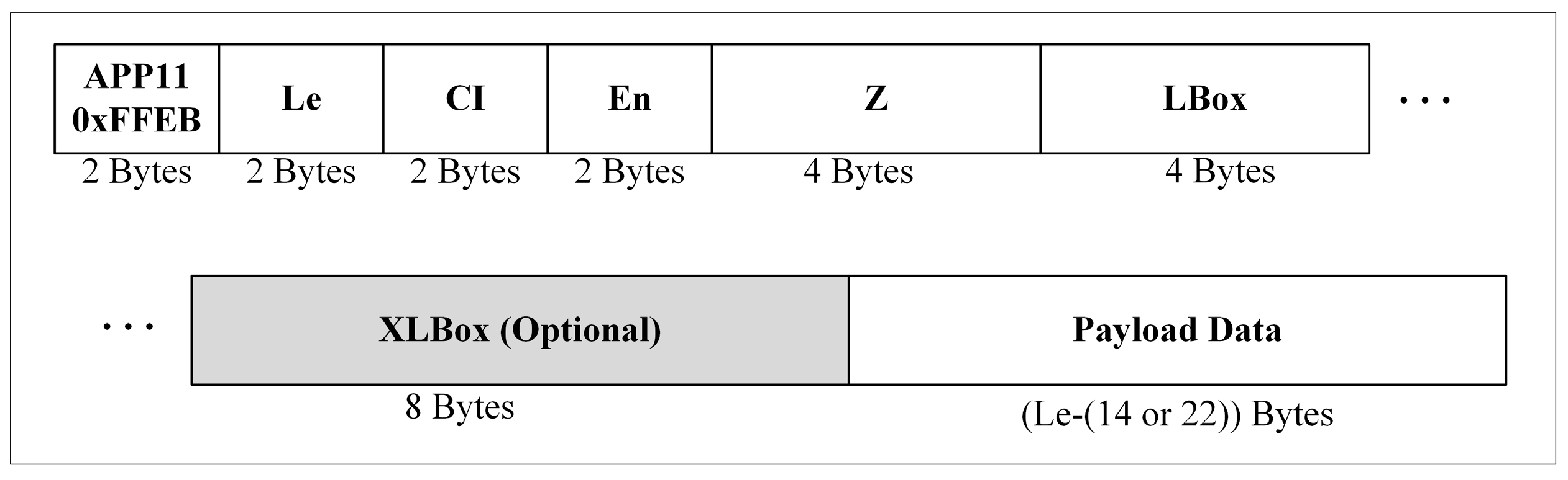
The APP11 marker wraps JPEG XT boxes [
14], as shown in
Figure 1. Although the JPEG-1 marker segment can carry data not more than 64 K bytes, there is a way that this box can logically carry more than 64 K bytes of payload data. A box with payload data greater than the capacity of the marker can be distributed into several APP11 marker segments. Syntax elements of the marker segment are responsible for instructing the decoder to combine the logically distributed boxes into one box. The ID assigned to the APP11 marker segment is 0xFFEB [
34].
In the APP11 marker, the two-byte length (Le) of the complete marker segment, except the marker’s ID, follows the ID bytes. The next two-byte field is the common identifier, which is fixed to ‘JP’ or ‘0x4A50’ The next two-byte field is the box instance (En) number. The number disambiguates payload data of the same box type and defines which payload data are concatenated. The next four-byte field represents the packet sequence number (Z). If the packet sequence number is different and the En is the same as the other APP11 marker segment’s number, then both segments logically belong to the same box.
After Z, the first four-byte field is the box length (LBox), which is the length of the concatenated payload data. If the value of the LBox is 1, it means that an extended box length (XLbox) field exists. The box type is represented by the next four-byte field. Box types define the purpose of the payload data. If the size of the payload data of a box exceeds the capacity of LBox, that is, 4 GB, then the XLbox field is used; otherwise, the XLbox field will not exist. A box is a generic data container that has both types and payload data. Some boxes may also contain other boxes. The box containing other boxes is called a super box.
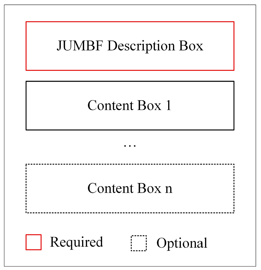
JUMBF provides a universal format for embedding and referring generic metadata in JPEG files. JPEG Systems Part 5 defines the syntax of the JUMBF box and specifies content types such as XML, JSON, Code Stream, and universally unique identifier (UUID). A JUMBF is a super box that contains exactly one JUMBF description box followed by one or more content boxes.
Figure 2 presents the structure of the JUMBF super box. The type specified for JUMBF super box is ‘jumb’ (0x6A756D62) [
12].
The behavior and content of the parent JUMBF box are provided by the JUMBF description box. The type of the description box is ‘jumd’ (0x6A756D64). The contents of the description box are defined as the first 16 bytes of UUID specifying the format of child content boxes in the super box. The next to UUID is a one-byte field, ‘toggle’, which signals the presence of label, ID, and signature fields in the description box. The size of the label field is variable, and ID and signature fields are 4 and 256 bytes in size, respectively.
Table 3 lists the currently defined content-type boxes in JPEG Systems. New content type boxes can be defined according to the needs of the JPEG WG or third party.


