
A Novel Distal Interlocking Screw Guidance System Using a Laser Pointer and a Mechanical Fine-Adjustment Device


Abstract
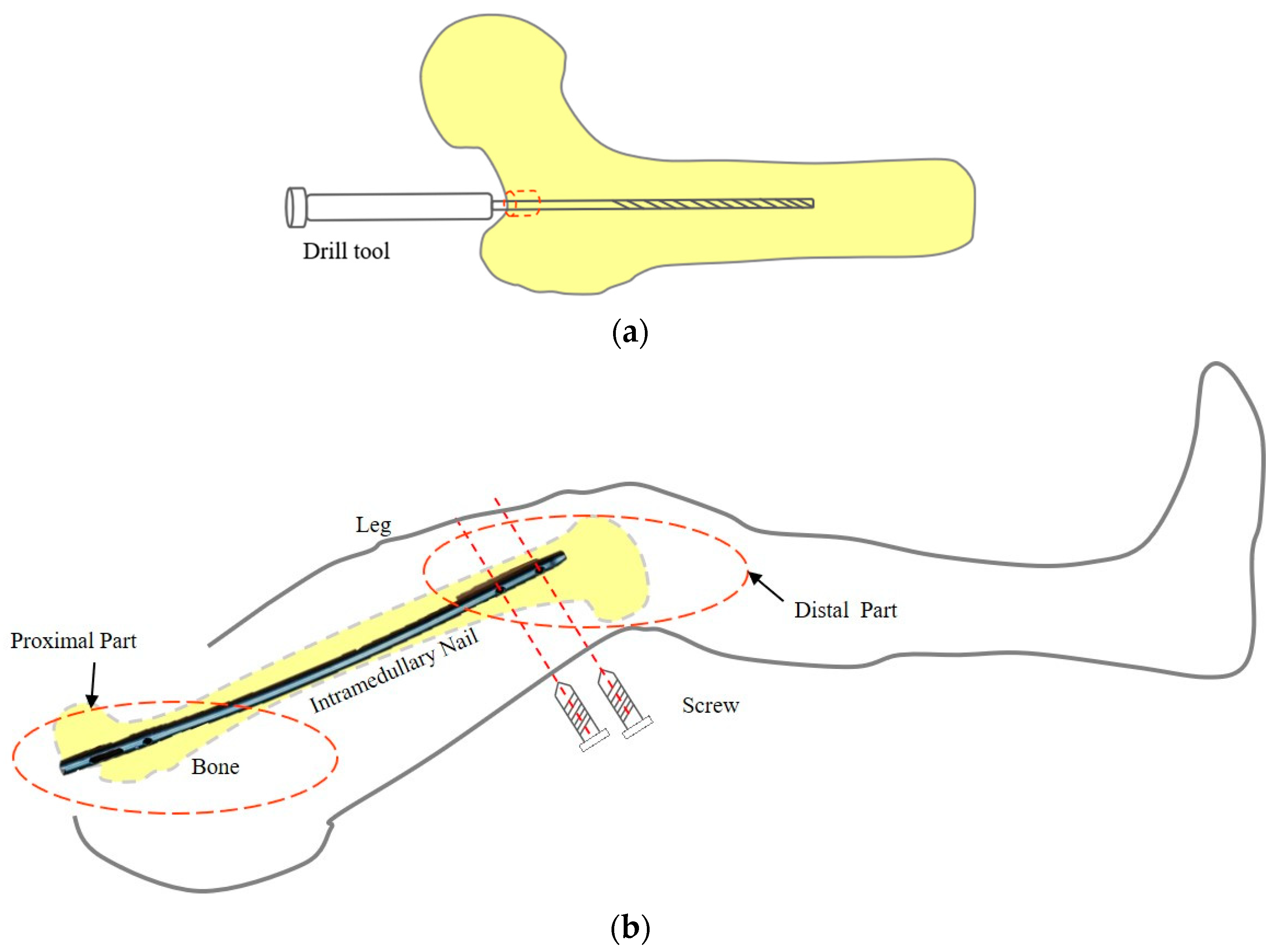
:1. Introduction
2. Materials and Methods
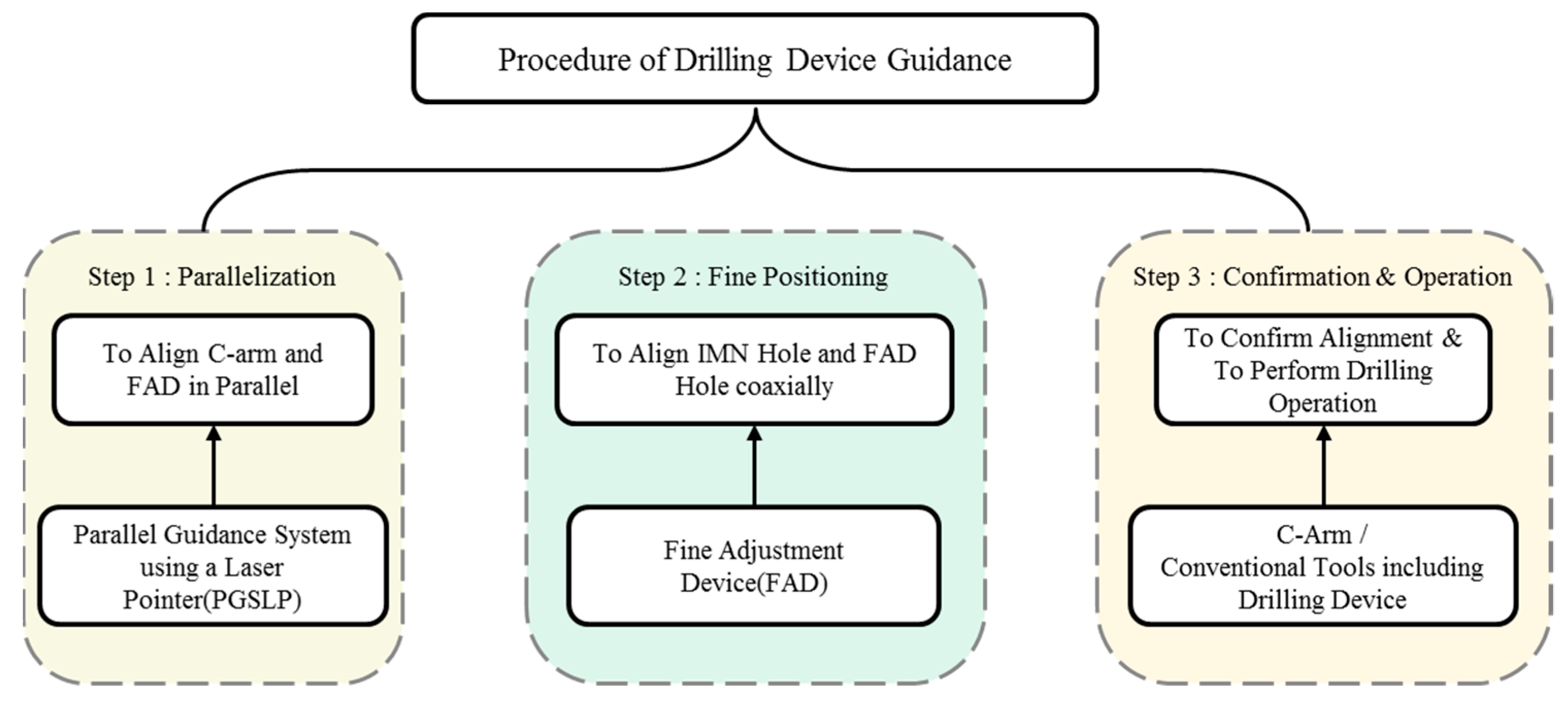
2.1. Procedure Using the Proposed System
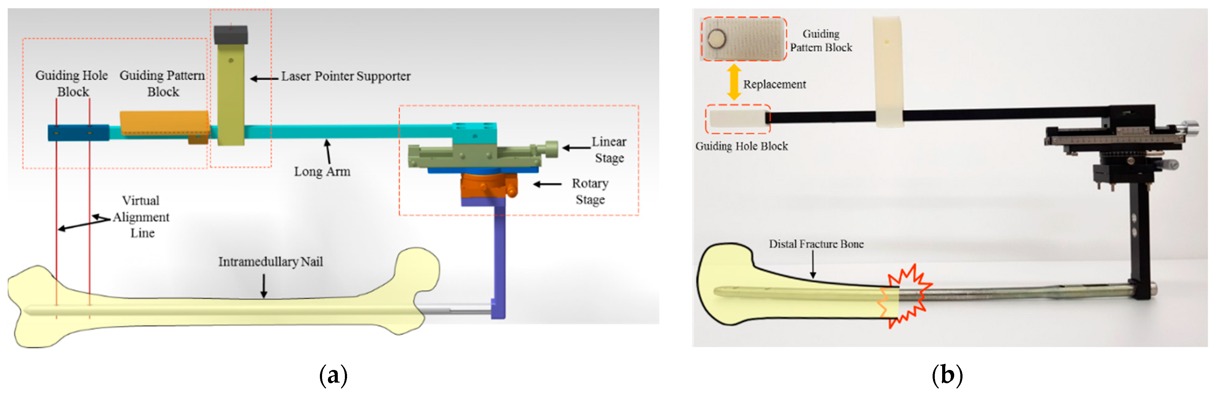
2.2. Fine Adjustment Device (FAD)
2.3. Parallelization of Planes of the C-Arm and FAD Using a Parallel Guidance System
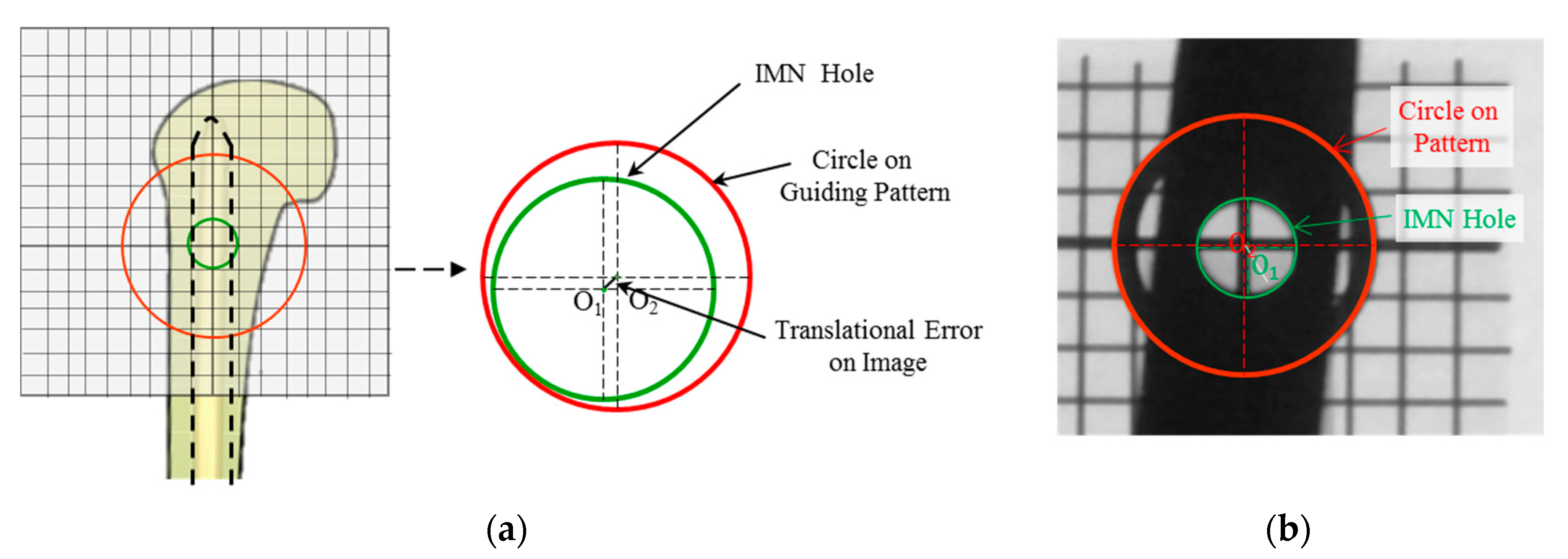
2.4. Fine Adjustment of the Guiding Pattern to the IMN Hole
3. Results
3.1. Experimental Setup
3.2. Evaluation Parameters
3.2.1. Tilted Angle Error during the Parallelization Step
3.2.2. Translation Error during Fine-Positioning Step
3.3. Experimental Results
4. Discussion
5. Conclusions
Author Contributions
Funding
Institutional Review Board Statement
Informed Consent Statement
Data Availability Statement
Acknowledgments
Conflicts of Interest
References
- Bong, M.R.; Koval, K.J.; Egol, K.A. The history of intramedullary nailing. Bull. NYU Hosp. Jt. Dis. 2006, 64, 94–97. [Google Scholar] [PubMed]
- Winquist, R.A.; Hansen, S.T.; Clawson, D.K. Closed intramedullary nailing of femoral fractures. A report of five hundred and twenty cases. J. Bone Jt. Surg. 1984, 66, 529–539. [Google Scholar] [CrossRef]
- Westphal, R.; Winkelbach, S.; Wahl, F.; Gösling, T.; Oszwald, M.; Hüfner, T.; Krettek, C. Robot-assisted Long Bone Fracture Reduction. Int. J. Robot. Res. 2009, 28, 1259–1278. [Google Scholar] [CrossRef]
- Dagnino, G.; Georgilas, I.; Morad, S.; Gibbons, P.; Tarassoli, P.; Atkins, R.; Dogramadzi, S. Image-Guided Surgical Robotic System for Percutaneous Reduction of Joint Fractures. Ann. Biomed. Eng. 2017, 45, 2648–2662. [Google Scholar] [CrossRef] [PubMed] [Green Version]
- Kim, W.Y.; Ko, S.Y.; Park, J.-O.; Park, S. 6-DOF force feedback control of robot-assisted bone fracture reduction system using double F/T sensors and adjustable admittances to protect bones against damage. Mechatronics 2016, 35, 136–147. [Google Scholar] [CrossRef]
- Yiannakopoulos, C.K.; Kanellopoulos, A.D.; Apostolou, C.; Antonogiannakis, E.; Korres, D.S. Distal Intramedullary Nail Interlocking: The Flag and Grid Technique. J. Orthop. Trauma 2005, 19, 410–414. [Google Scholar] [CrossRef] [PubMed]
- Tyropoulos, S.; Garnavos, C. A new distal targeting device for closed interlocking nailing. Injury 2001, 32, 732–735. [Google Scholar] [CrossRef]
- Windolf, M.; Schroeder, J.; Fliri, L.; Dicht, B.; Liebergall, M.; Richards, R.G. Reinforcing the role of the conventional C-arm—A novel method for simplified distal interlocking. BMC Musculoskelet. Disord. 2012, 13, 8. [Google Scholar] [CrossRef] [PubMed] [Green Version]
- Distalock, Llc. Available online: http://www.distalock.com (accessed on 12 May 2017).
- Pardiwala, D.; Prabhu, V.; Dudhniwala, G.; Katre, R. The AO distal locking aiming device: An evaluation of efficacy and learning curve. Injury 2001, 32, 713–718. [Google Scholar] [CrossRef]
- Zheng, G.; Zhang, X.; Haschtmann, D.; Gedet, P.; Dong, X.; Nolte, L.-P. A Robust and Accurate Two-Stage Approach for Automatic Recovery of Distal Locking Holes in Computer-Assisted Intramedullary Nailing of Femoral Shaft Fractures. IEEE Trans. Med Imaging 2008, 27, 171–187. [Google Scholar] [CrossRef]
- Wong, T.-H.; Chung, T.-K.; Liu, T.-W.; Chu, H.-J.; Hsu, W.; Yeh, P.-C.; Chen, C.-C.; Lee, M.-S.; Yang, Y.-S. Electromagnetic/Magnetic-Coupled Targeting System for Screw-Hole Locating in Intramedullary Interlocking-Nail Surgery. IEEE Sens. J. 2014, 14, 4402–4410. [Google Scholar] [CrossRef] [Green Version]
- Chung, T.K.; Chu, H.J.; Wong, T.H.; Hsu, W.; Lee, M.S.; Lo, W.T.; Tseng, C.Y. An Electromagnetic-Induction Approach for Screw-Hole Targeting in Interlocking-Nail Surgery. In Proceedings of the SENSORS, 2012 IEEE, Taipei, Taiwan, 28–31 October 2012. [Google Scholar]
- Lee, M.; Wu, S.; Wong, T.; Hsu, W.; Chung, T. A Novel Guiding Device for Distal Locking of Intramedullary Nails. In Proceedings of the SENSORS, 2012 IEEE, Taipei, Taiwan, 28–31 October 2012. [Google Scholar]
- Darwish, B.; Lotfy, A.; Younes, S. Accurate Determination of the Sites of the Distal Hole of the Humeral Interlocking Intramedullary Nail Using Monofilament Solid Core Optical Fiber. Int. J. Sci. Basic Appl. Res. 2015, 23, 111–122. [Google Scholar]
- Choi, J.; Kim, J.; Hwang, J.Y.; Je, M.; Kim, J.-Y.; Kim, S.-Y. A novel smart navigation system for intramedullary nailing in orthopedic surgery. PLoS ONE 2017, 12, e0174407. [Google Scholar] [CrossRef] [PubMed]
- Yaniv, Z.; Joskowicz, L. Precise robot-assisted guide positioning for distal locking of intramedullary nails. IEEE Trans. Med Imaging 2005, 24, 624–635. [Google Scholar] [CrossRef] [PubMed]
- An, L.; Kim, W.Y.; Ko, S.Y.; Liming, A. Robotic Guidance of Distal Screwing for Intramedullary Nailing Using Optical Tracking System. J. Korea Robot. Soc. 2017, 12, 411–418. [Google Scholar] [CrossRef]
- Rashid, M.S.; Aziz, S.; Haydar, S.; Fleming, S.S.; Datta, A. Intra-operative fluoroscopic radiation exposure in orthopaedic trauma theatre. Eur. J. Orthop. Surg. Traumatol. 2018, 28, 9–14. [Google Scholar] [CrossRef] [PubMed] [Green Version]


| Subject | Index | Parallelization Time (s) | Fine Positioning Time (s) | Total Time (s) | No. of X-ray Images (EA) | X-ray Exposure (cGy-cm2) |
|---|---|---|---|---|---|---|
| S1 | T1 | 72 | 145 | 217 | 6 | 1.14 |
| S1 | T2 | 16 | 336 | 352 | 10 | 2.71 |
| S1 | T3 | 52 | 342 | 394 | 10 | 3.67 |
| S2 | T4 | 51 | 310 | 361 | 7 | 2.94 |
| S2 | T5 | 27 | 205 | 232 | 6 | 2.58 |
| S2 | T6 | 31 | 238 | 269 | 9 | 2.66 |
| S3 | T7 | 27 | 140 | 167 | 6 | 1.22 |
| S3 | T8 | 63 | 81 | 144 | 3 | 1.00 |
| S3 | T9 | 31 | 64 | 95 | 3 | 1.31 |
| Average ± STD | 41.1 ± 19.0 | 207 ± 107 | 248 ± 105 | 6.67 ± 2.65 | 2.14 ± 0.97 | |
| Index | T1 | T2 | T3 | T4 | T5 | T6 | T7 | T8 | T9 | Average ± STD |
|---|---|---|---|---|---|---|---|---|---|---|
| Tilted angle error (°) | 0.950 | 1.20 | 1.01 | 0.280 | 0.200 | 2.15 | 2.18 | 1.64 | 1.51 | 1.24 ± 0.715 |
| Translational Error (mm) | 0.150 | 0.390 | 0.390 | 0.240 | 0.400 | 0.470 | 0.380 | 0.560 | 0.420 | 0.378 ± 0.120 |
Publisher’s Note: MDPI stays neutral with regard to jurisdictional claims in published maps and institutional affiliations. |
© 2021 by the authors. Licensee MDPI, Basel, Switzerland. This article is an open access article distributed under the terms and conditions of the Creative Commons Attribution (CC BY) license (https://creativecommons.org/licenses/by/4.0/).
Share and Cite
Xu, B.; An, L.; Ko, S.Y. A Novel Distal Interlocking Screw Guidance System Using a Laser Pointer and a Mechanical Fine-Adjustment Device. Appl. Sci. 2021, 11, 11109. https://doi.org/10.3390/app112311109
Xu B, An L, Ko SY. A Novel Distal Interlocking Screw Guidance System Using a Laser Pointer and a Mechanical Fine-Adjustment Device. Applied Sciences. 2021; 11(23):11109. https://doi.org/10.3390/app112311109
Chicago/Turabian StyleXu, Binxiang, Liming An, and Seong Young Ko. 2021. "A Novel Distal Interlocking Screw Guidance System Using a Laser Pointer and a Mechanical Fine-Adjustment Device" Applied Sciences 11, no. 23: 11109. https://doi.org/10.3390/app112311109
APA StyleXu, B., An, L., & Ko, S. Y. (2021). A Novel Distal Interlocking Screw Guidance System Using a Laser Pointer and a Mechanical Fine-Adjustment Device. Applied Sciences, 11(23), 11109. https://doi.org/10.3390/app112311109