Article

A Novel Distal Interlocking Screw Guidance System Using a Laser Pointer and a Mechanical Fine-Adjustment Device

1
College of Mechanical and Electrical Engineering, Shaoxing University, Shaoxing 312000, China
2
Department of Mechanical Engineering, Chonnam National University, Gwangju 61186, Korea
*
Author to whom correspondence should be addressed.
These authors contributed equally to this work.
Appl. Sci. 2021, 11(23), 11109; https://doi.org/10.3390/app112311109
Submission received: 14 October 2021 / Revised: 17 November 2021 / Accepted: 20 November 2021 / Published: 23 November 2021
(This article belongs to the Special Issue Frontiers in Medical Robotics)

Abstract

:
In minimally invasive bone fracture reduction surgery, broken femur bones are firmly fixed to a metallic intramedullary nail (IMN) after they are properly aligned. One of the greatest challenges of this process is that surgeons cannot directly see holes on the IMN, which increases the difficulty of the procedure and results in the requirement of taking a large number of X-ray images to find the location and direction of holes. We propose a novel distal interlocking screw guidance system that consists of a parallel guidance system using a laser pointer (PGSLP) and a mechanical fine-adjustment device (FAD). The PGSLP is used to make the planes of the C-arm and FAD parallel. The FAD is used to concentrically align the IMN hole with the guiding hole. The performance of the proposed device was evaluated by a series of experiments. The tilted angle error between the C-arm and FAD was measured to be 1.24 ± 0.715°. The translational error between the IMN hole and guiding hole was measured to be 0.378 ± 0.120 mm. Since the proposed guiding system is simple, cost-effective, and accurate, we expect it will soon be used in real operations.

1. Introduction

When a long bone, such as a femur, is broken, a fracture reduction surgery is performed to align the broken fractures and to fix them to a metallic member. Since the intramedullary nailing treatment was first developed by Gerhard Kuntscher in 1940 [1], closed intramedullary nailing has become the most common treatment for fracture reduction surgery [2], which is performed with minimal opening of the tissue. The procedure is shown in Figure 1. First, a small window between the femoral head and the greater trochanter is created using a drilling tool and a canal reamer, as shown in Figure 1a. Then, a thin guide wire is inserted into the fractured bone. Next, the intramedullary nail (IMN) is inserted in the fractured bone along with the guide wire, and the interlocking screws are fixed to the IMN holes, as shown in Figure 1b. Once complete, the wounds are closed. One of the most challenging tasks in this operation is to insert the interlocking screws to fix the fractured bones to the IMN because surgeons cannot see the IMN hole directly, and therefore it becomes difficult to insert the screws accurately. For this procedure, the surgeons conventionally use the C-arm device to align the position and orientation of the screw to those of the IMN hole simultaneously, despite the large potential harm of X-ray exposure to the surgeons and patients. Recently, robot-assisted bone fracture reduction surgery systems have been actively studied [3,4,5], most of which alleviate the load of the reduction procedure not on the screwing.
To solve this issue, various methods have recently been proposed. The first category includes mechanical devices [6,7,8,9] for facilitating finding the hole location. Yiannnakopulos et al. [6] used a grid marker and a flag to roughly predict the position of the IMN hole. Its effectiveness was confirmed through in vivo testing. However, it did not describe how to align the drilling direction to that of the IMN hole. Tyropoulos et al. [7] developed a mechanical jig device to align to the IMN hole by translation in the directions of up, down, left, and right. The alignment of the screwing direction needed to be checked using X-ray images. Windolf et al. [8] proposed a mechanical jig to accurately modify the position as well. Recently, Distalock, LLC [9] released a new device that drills from the inside to the outside of the bone to find the screw position. The disadvantage of this is that it cannot make a hole perfectly perpendicular to the IMN hole, resulting in possible incorrect guiding of the screw.
The second category includes methods that utilize image processing. With the help of fluoroscopy [10,11], surgeons can check the position of IMN hole by taking X-ray images to find the proper position of screws. This technique does not eliminate X-ray exposure. They guide the direction of the drilling tool virtually not physically. The C-arm should be calibrated accurately, which is not a simple task due to the arm deformation. Finally, environmental conditions such as X-ray strength and the distance to the object can affect the targeting accuracy of the IMN hole.
The third category includes methods that use magnetic fields [12,13,14] to eliminate the necessity of X-ray images. However, the accuracy is not sufficient to be used in real operations and it is easily affected by surrounding metal equipment. Different from all three categories, Darwish et al. [15] proposed a new approach to visualize the hole location by using optical fiber that delivers strong illumination into the bone cavity. However, the illumination could not penetrate the tissue, which resulted in a large incision on the patient. It also was not accurate enough to use in real operations. Choi et al. [16] proposed a guiding method using a laser beam to visualize the hole locations but the drilling procedure needed to be performed with a free hand, which is unstable. Robotic guidance systems were also proposed [17,18]; however, using robotic systems is expected to be cumbersome and expensive. In addition, they require more evaluation to confirm their feasibility.
In this study, a novel distal interlocking screw guidance system is proposed, consisting mainly of a parallel guidance system using a laser pointer (PGSLP) and a mechanical fine-adjustment device (FAD). In conventional surgery, a large number of X-rays are required, exposing surgeons as they try to move the C-arm to align the drilling axis with the IMN hole by trial and error. To reduce the X-ray exposure while minimizing the extra cost for the equipment, we broke down the alignment procedure into two sub-steps: parallelization and fine positioning. The parallelization step is carried out to simplify the fine-positioning step, in which the hole of the FAD is aligned to that of the IMN. One of the advantages of the proposed system is the cost-effectiveness compared to other advanced systems, i.e., [18] using expensive surgical equipment such as an optical tracking system (OTS) and surgical robots. In addition, using the proposed system would reduce both the exposure to X-ray radiation and the targeting time required to target the position and orientation of the IMN hole.

2. Materials and Methods

2.1. Procedure Using the Proposed System

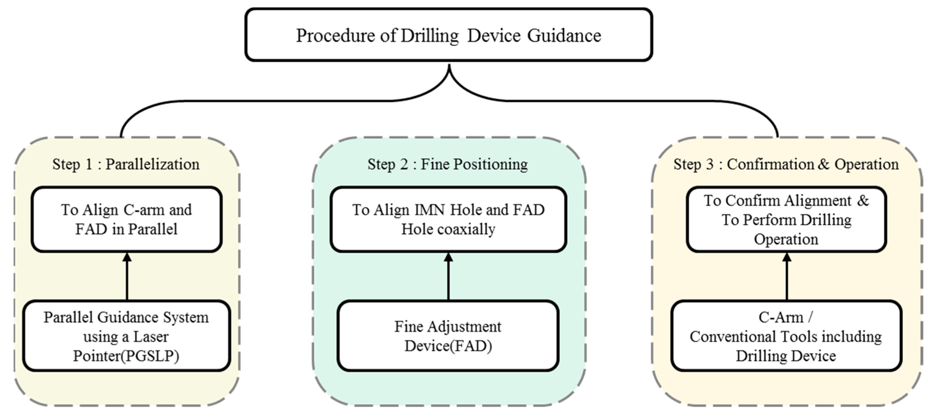
The goal of distal interlocking screwing is to fix interlocking screws into IMN holes. The goal of this work was to accurately align the drilling device for the guide wire with the IMN hole, with reduced X-ray exposure. In our work, we separated the procedure into three steps, as shown in Figure 2, including the parallelization step and the fine-positioning step. The FAD is designed to be attached to the proximal end of the IMN, and its long arm is made to extend in parallel to the IMN. There are screw guiding holes on the FAD arm that will be aligned to the holes of the IMN. For easier operation, we designed it so that a block with the screw guiding holes can be replaced with a block that has the grid and circular pattern. In the parallelization step, the position of the C-arm is adjusted so that the plane of C-arm is parallel to the upper plane of the FAD. This is done using a reflected image of the beam from a laser pointer to eliminate the need for X-rays. This procedure simplifies the alignment of the FAD hole (or circular pattern) and the IMN hole by making their axes parallel. For this, it was assumed that the direction of IMN hole did not vary significantly during the FAD attachment process, and thus only the translation needs to be adjusted afterward. If the parallelism is established, the IMN hole will appear to be circular in the X-ray image. For this step, we proposed using a parallel guidance system using a laser pointer (PGSLP). In the fine-positioning step, the FAD is used to coaxially align the IMN hole with the hole (or circular pattern) of the FAD. During this step, X-ray images are needed to check the relative position of the IMN hole to the FAD pattern. By restricting the FAD arm motion to one plane and by making the surgeon expect the amount of adjustment using grid and circular patterns, we significantly reduced the number of X-ray shots and the amount of required time. In Section 3, the comparison between this work and conventional bone reduction surgery also proves this argument. Simple mechanical jigs can be used, the holes of which are exactly aligned to the IMN holes. However, a fine adjustment function is included in the proposed system because an error may occur due to the misalignment of the attachment between the FAD and IMN and due to deformation of the IMN itself. Finally, in the confirmation and operation step, the operating surgeon confirms the alignment between the IMN hole and the FAD circular pattern, and then replaces the pattern block with the guiding hole block. After that, the drilling operation is conducted using conventional tools such as a drilling device and a guide wire.

2.2. Fine Adjustment Device (FAD)

Figure 3 shows the three-dimensional (3D) model of the FAD and its fabricated prototype. It is composed of a passive linear stage (XLSL120-2, 2 mm/rotation, Misumi Co., Japan), a passive rotary stage (RTRM40-R, 5°/rotation, Misumi Co., Japan), a laser pointer supporter, a long arm, a guiding hole block, and a guiding pattern block. Two passive stages are used to move the long arm in a plane. Using these, the operator can accurately adjust the position of the hole. The laser pointer supporter includes the laser pointer inside and was used as a part of the PGSLP that is described in Section 2.3. The guiding hole block has holes to guide the drilling device, and the guiding pattern block includes the grid and circular patterns for easier adjustment. In our work, the grid pattern and the circular pattern were used together to combine the advantages of each [6,10]. Either of two blocks can be fixed to the long arm of the FAD by replacement. As shown in Figure 4a, the dimension of the pattern block was 80 mm by 40 mm and included the thin metal wires arranged in a grid pattern at 4 mm intervals, as shown in Figure 4a,b. For the grid pattern, nitinol wires that were 1.33 mm in diameter were used for the principal axes and wires that were 0.72 mm in diameter were used for other lines, as shown in Figure 4b. The pattern block also included one circular metal part (outer diameter: 20 mm, inner diameter: 16 mm) as in Figure 4, which helps the operator make the circles co-axial. The intersection point of two thick nitinol wires was set to the center of the ring pattern. The X-ray image of the guiding pattern block is shown in Figure 4c.

2.3. Parallelization of Planes of the C-Arm and FAD Using a Parallel Guidance System

To make the planes of the C-arm and FAD parallel, we propose a PGSLP in this paper. PGSLP is mainly composed of a reflector and a laser pointer. The reflector is attached to the image panel of the C-arm and, if necessary, it can be attached to the surface of the X-ray source. The laser pointer is attached to the FAD such that the direction of the laser is parallel to the axis of the hole. When the direction of the laser beam is perpendicular to the reflector, the reflected image of the laser is projected to the laser pointer itself. When the reflector is tilted, the image moves to the tilted direction. Roughly speaking, assuming the distance between the C-arm and FAD is D = 0.7 m and the tilted angle is δθ = 1°, it produces the offset error δε = D tan (2δθ) = 0.0244 m = 24.4 mm, which means that the sensitivity is sufficiently high. Figure 5 is a detailed illustration of the process of aligning the C-arm relative to the FAD. During the operation, when the IMN is inserted and the FAD is fixed on its proximal end, the position of FAD and the direction of the laser pointer are arbitrary, as shown in Figure 5a. Then, the C-arm is moved to put the FAD within C-arm range, allowing it to be roughly aligned, as shown in Figure 5b. Since we cannot move the FAD freely, we need to move C-arm for the parallelization. The position of the C-arm is adjusted translationally to move the laser image near the center of C-arm panel (as shown in Figure 5c) and rotationally to make the two planes parallel (as shown in Figure 5d). If necessary, the translation adjustment and the rotation adjustment can be repeated until the reflected laser image returns to the laser pointer.

2.4. Fine Adjustment of the Guiding Pattern to the IMN Hole

After the parallelization step, the mechanical FAD is used to align the guiding hole with the IMN hole. Since the FAD is now parallel to the C-arm and the motion of the hole (or the center of guiding pattern) is restricted to a plane, two degree of freedom (DOF) planar motion would be sufficient. For this, the passive linear stage and the passive rotary stage are integrated into the FAD. The linear stage moves the guiding pattern forward and backward by 2 mm per rotation. The rotational stage rotates it by 5 degrees per rotation, which produces a lateral motion of about 30 mm per rotation. In order to facilitate the fine adjustment process, we marked the grid pattern at 4 mm intervals, as mentioned in Figure 4. On the basis of this pattern, we were able to estimate the distance between the IMN hole and the center of the guiding pattern. As a result, the offset of one grid in the forward/backward direction corresponded to two rotations of the linear stage and the offset of one grid in the lateral direction corresponded to about 13% of a rotation of the rotary stage. Although the guiding pattern was placed closer than the IMN hole, the guiding pattern needed to move, and therefore further calibration due to the depth difference was not required. The adjustment process can be done repeatedly until the two holes become concentric. Figure 6 shows the case when the guiding pattern is not aligned yet (Figure 6a) and the case when it is perfectly aligned (Figure 6b). Here, the red circle is a circle of the guiding pattern, and the green circle is the IMN hole.

3. Results

3.1. Experimental Setup

Figure 7 shows the experimental setup for the evaluation of the proposed approach. In addition to the developed FAD and PGSLP, a real C-arm (Ziehm Vision RFD 3D from Ziehm Imaging GmbH, Germany) and an optical tracking system (Polaris Spectra from Northern Digital Inc., Canada) were used, as shown in Figure 7a. For the PGSLP, a low-cost laser pointer (LP-12 from LASMAC) was installed at the FAD perpendicular to the guiding pattern, i.e., parallel to the guiding hole. A mirror-like reflector sheet was attached to the surface of the image panel of the C-arm. The FAD was attached to the movable frame using a passive fixing jig. As shown in Figure 7a,b, two markers were used for evaluation: one for the FAD and the other for the C-arm.

3.2. Evaluation Parameters

3.2.1. Tilted Angle Error during the Parallelization Step

The first parameter used to evaluate was the tilted angle error. For this, the C-arm marker and the FAD marker of the optical tracking system were attached to the plane of the image panel of the C-arm and the plane of the guiding pattern block, respectively, as shown in Figure 8. The coordinate systems {C-arm} and {FAD} were also assigned to markers, as defined in Figure 8. The X-axis of {C-arm} was defined as the normal vector of the C-arm plane, and the Z-axis of {FAD} was defined as the normal vector of the guiding pattern block of the FAD. Thus, the tilted angle error was defined as the error between the two axes that are marked as red arrows, which can be obtained using the formula of the Euclidean dot product as in Equation (1).
θ = acos (   X   c arm ·   Z   FAD   X   c arm ·   Z   FAD )

3.2.2. Translation Error during Fine-Positioning Step

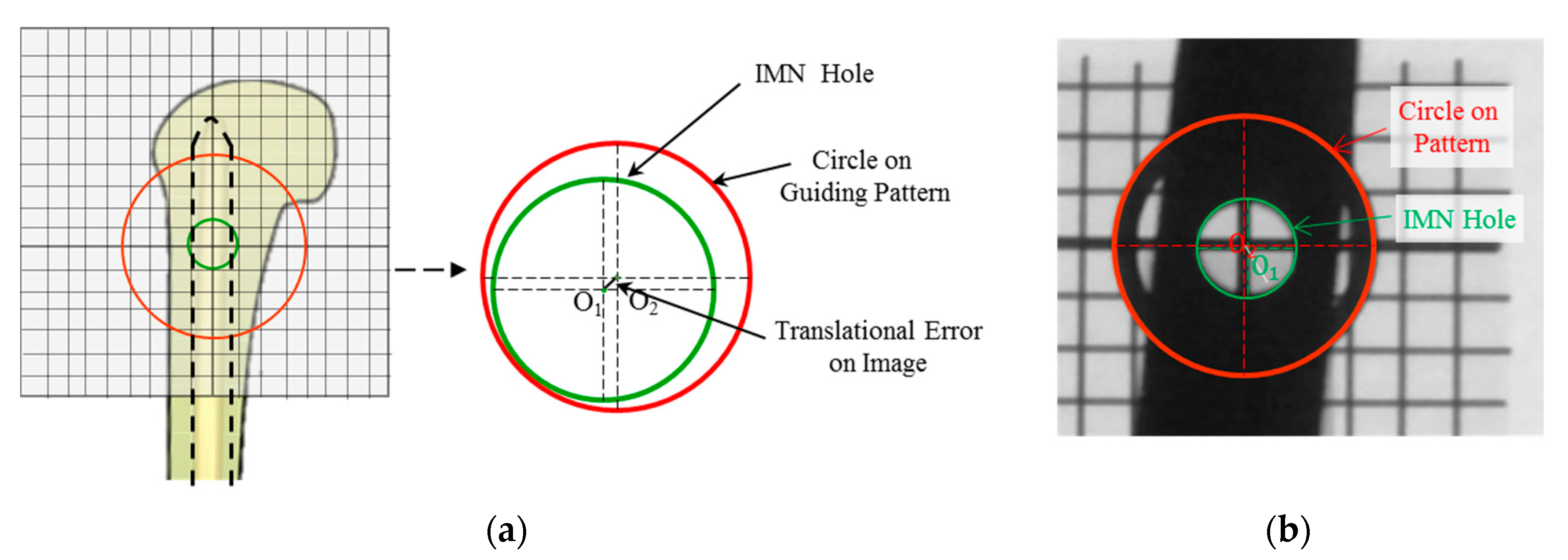
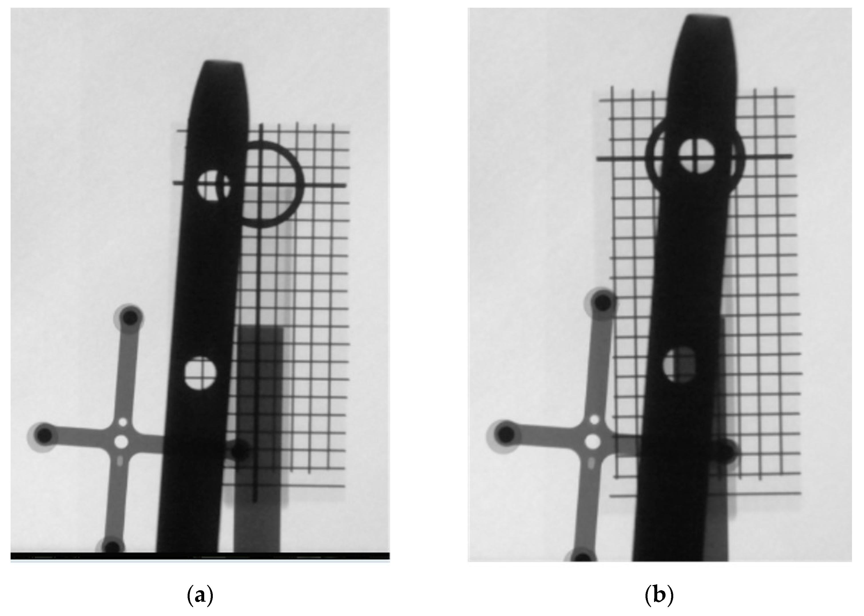
The second parameter is the translational error of the IMN hole with respect to the axis of the guiding hole, or the normal axis of the guiding pattern. Because we assumed that the two planes became parallel during the first step, the error value was evaluated using X-ray images taken by the C-arm. As shown in Figure 9, the projected images of the IMN hole in green and the circle on the guiding pattern in red were both circular. Since the real outer diameter of the circle on the guiding pattern block dGuiding_Pattern_Real was 20 mm, the real error value can be calculated as in Equation (2). When the X-ray image was acquired after the repeated fine-positioning process, the center of the IMN hole O1, and the center of the circle on the guiding pattern O2, were identified manually, and the distance (O1O2) on the X-ray image dO1 O2_Error_Image was measured. Then the real translational error PO1 O2_Error_Real was calculated as in Equation (2). Figure 10 shows the X-ray images before and after the fine-positioning step during the evaluation. Because the circle on the pattern block was larger than the IMN, it was easy to roughly align them. The grid pattern helps the surgeon to adjust the origin of the gird pattern toward the center of the IMN hole.
P O 1 O 2 _ Error _ Real = d Guiding   Pattern _ Real d Guiding   Pattern _ Image   d O 1 O 2 _ Error _ Image

3.3. Experimental Results

For the evaluation, the experimental setup was prepared as described in Figure 7, in which the position of the FAD was placed arbitrarily. Three novice people who had no experience on the distal screwing operation performed the experiment. The subjects first tried to roughly relocate the C-arm to put the FAD within the range of C-arm view, attempting to make the two planes parallel. After that, the subjects tried to align the guiding pattern to the IMN hole. During these experiments, we measured the following parameters: (1) Parallelization time to make the planes of the C-arm and the FAD parallel. (2) Fine-positioning time to adjust the IMN hole position from the misaligned state to the aligned state. (3) Total operation time, which is the sum of the parallelization time and the fine-positioning time. (4) Number of X-ray images taken during the fine-positioning step. (5) The amount of X-ray radiation that is indicated by the C-arm device. Three subjects performed the guiding process three times each, and the measured data are listed in Table 1 and Table 2. As shown in Table 1, the average parallelization time was measured to be 41.1 s with a standard deviation (STD) of 19.0 s. The average fine-positioning time was measured to be 207 s with a STD of 107 s and the total operation time to be 248 s with a STD of 105 s. Please note that in order to eliminate X-ray exposure to the subjects, when the FAD position was modified, the subjects left the X-ray shielding room and executed X-ray shooting remotely. In a real situation, however, an operating surgeon would shoot the X-ray in situ while changing the FAD position, and thus the time would be expected to be reduced significantly. Owing to this, the fine-positioning time measured was much longer than the expected time in a real operating room. To show the effectiveness of the proposed system, we also provide the X-ray images taken in Table 1. The number of X-ray images taken ranges from 3 to 10 times, with an average of 6.67 and a STD of 2.65 times. The average dose of X-ray exposure was 2.14 with a STD of 0.97 cGy-cm2, which are significantly smaller than the normal procedure as shown in [19], where the data were investigated from 39 cases, and which showed the number of X-ray images was 243 and the dose of X-ray exposure was 172 cGy-cm2. In addition, we also measured the tilted angle error and the translation error following the method aforementioned in Section 3.2. As shown in Table 2, the tilted angle error during the parallelization step was measured to be 1.24 ± 0.715°, and the translation error during the fine-positioning step was measured to be 0.378 ± 0.120 mm. We believe these results are also sufficient for the distal screwing process.

4. Discussion

The experimental evaluation performed in the previous section showed that the proposed system has accurate alignment performance for the distal screwing guidance while minimizing use of X-ray images. One of the important assumptions of this study was that guidance using the conventional mechanical jig has inherent limitation because the position of the jig changes during the assembly process and/or because the IMN itself deforms within the bone cavity during the insertion process. Thus, we divided the guidance process for distal screwing into two steps, a parallelization step and a fine-positioning step, for accurate and easy manipulation. A parallel guidance system with a laser pointer (PGSLP) was developed for the parallelization step, and a mechanical fine-adjustment device (FAD) was developed for the fine-positioning step. Previously, several mechanical jig systems had been proposed for guidance [6,7,8], but most of them did not mention how to align the drilling direction of the IMN hole efficiently to reduce the X-ray exposure. Different from these, the proposed system using the PGSLP and the FAD is novel, time-saving, and cost-effective. Although we could not completely eliminate the necessity of X-ray imaging, we believe that shooting 3~10 X-ray images are acceptable for this operation.
The experiments showed that the parallelization process could be done in 72 s at maximum and 41.1 ± 19.0 s on average, and no X-ray image was needed at all. The tilted angle error was 2.18° at maximum and 1.24 ± 0.715° on average. During the experiments, it was possible to move the C-arm to make the offset of the reflected image of the laser pointer less than 5 mm, which is expected to produce sub-degree tilted angle error. However, the final results were somewhat larger than expected. It is believed that it is due to the calibration error of attaching the OTS markers. Thus, the calibration accuracy should be increased in order to improve the overall performance evaluation in future work. The C-arm used in this study can be remotely operated; however, in this experiment, manual operation was used in order to observe the feasibility of the proposed system using the conventional C-arm and also because manual operation was easier than remote operation. To remotely operate, additional mechanisms, such as a camera to visualize the position of the reflected image of the laser pointer and the advanced control algorithm using the kinematics of the C-arm, are required.
In order to make the fine-positioning step easier, we integrated an additional guiding pattern into the FAD in our study. However, due the interference between the guiding pattern and the guiding hole, they were made into blocks, and only one of them was attached to the FAD. Thus, the final goal of this study was set to aligning the center of the guiding pattern with the IMN hole using the guiding pattern. The experiments showed that this task took 342 s at maximum and 207 ± 107 s on average, requiring X-ray imaging 10 times at a maximum and 6.67 ± 2.65 times on average. The reason it takes a long time for a small number of X-ray images is because we took X-ray images after the subjects left the X-ray shielding room, when modifying the position of the FAD, in order to reduce their radiation exposure. We believe that the time can be reduced significantly if the surgeons use the C-arm without leaving the X-ray shielding room. As indicated in [6], the conventional distal interlocking using a freehand technique can take 19 ± 7.1 min. Since the most challenging and time-consuming step in distal interlocking is intramedullary hole identification, it takes most of the time in distal interlocking. Although it is not fair comparison, it can be said that the proposed intramedullary hold identification method requires a shorter period of time than the conventional method.
Finally, we did not perform the actual screwing operation using the guiding hole block, but it will be verified in future work. In addition, the optical tracking system was used only for the evaluation and thus was not part of our proposed system. We believe that the whole mechanism is cost-effective while guaranteeing high accuracy in the guidance task.

5. Conclusions

This study proposed a novel interlocking screw guidance system that enables cost-effective and accurate drill guidance for distal screwing procedures of a femur fracture reduction surgery. In the conventional operation, a lot of X-ray images are required in finding the direction and position of the hole, and therefore our guidance process was divided into a parallelization step and a fine-positioning step. A parallel guidance system was developed for the parallelization step, and a mechanical fine-adjustment device was developed for the fine-positioning step. The experiment results using the real C-arm devices showed that the parallelization step took 41.1 ± 19.0 s, and the tilted angle error was measured as 1.24 ± 0.715°. The fine-positioning step took 207 ± 107 s and was possible only using X-ray imaging 6.67 ± 2.65 times. The translation error was measured as 0.378 ± 0.120 mm. These values are considered sufficient for the system to be used in real operations.
In future work, evaluation on the drilling process using a real C-arm will be performed. It was verified that the tilting angle error and the translation error are sufficiently small using X-ray-based analysis, but the actual drilling guidance experiment is required for final validation. Moreover, an ex vivo experiment using animal bones will be performed after the drilling evaluation.

Author Contributions

Conceptualization, S.Y.K.; methodology, L.A.; validation, B.X. and L.A.; formal analysis, L.A.; writing—original draft preparation, L.A.; writing—review and editing, B.X. and S.Y.K.; supervision, S.Y.K.; funding acquisition, S.Y.K. All authors have read and agreed to the published version of the manuscript.

Funding

This work was supported by the Korea Medical Device Development Fund grant funded by the Korean government (the Ministry of Science and ICT, the Ministry of Trade, Industry and Energy, the Ministry of Health and Welfare, the Ministry of Food and Drug Safety) (project number: KMDF_PR_2020901_0122, 9991007296) and was supported by the National Research Foundation of Korea (NRF) grant funded by the Korean government (MSIT) (no. 2019R1A2C2091005).

Institutional Review Board Statement

Not applicable.

Informed Consent Statement

Not applicable.

Data Availability Statement

The data presented in this study are available on request from the corresponding author.

Acknowledgments

The authors thank the medical microrobot center, Chonnam National University in Korea for their support for the use of C-arm device and X-ray shielding room.

Conflicts of Interest

The authors declare no conflict of interest.

References

  1. Bong, M.R.; Koval, K.J.; Egol, K.A. The history of intramedullary nailing. Bull. NYU Hosp. Jt. Dis. 2006, 64, 94–97. [Google Scholar] [PubMed]
  2. Winquist, R.A.; Hansen, S.T.; Clawson, D.K. Closed intramedullary nailing of femoral fractures. A report of five hundred and twenty cases. J. Bone Jt. Surg. 1984, 66, 529–539. [Google Scholar] [CrossRef]
  3. Westphal, R.; Winkelbach, S.; Wahl, F.; Gösling, T.; Oszwald, M.; Hüfner, T.; Krettek, C. Robot-assisted Long Bone Fracture Reduction. Int. J. Robot. Res. 2009, 28, 1259–1278. [Google Scholar] [CrossRef]
  4. Dagnino, G.; Georgilas, I.; Morad, S.; Gibbons, P.; Tarassoli, P.; Atkins, R.; Dogramadzi, S. Image-Guided Surgical Robotic System for Percutaneous Reduction of Joint Fractures. Ann. Biomed. Eng. 2017, 45, 2648–2662. [Google Scholar] [CrossRef] [PubMed] [Green Version]
  5. Kim, W.Y.; Ko, S.Y.; Park, J.-O.; Park, S. 6-DOF force feedback control of robot-assisted bone fracture reduction system using double F/T sensors and adjustable admittances to protect bones against damage. Mechatronics 2016, 35, 136–147. [Google Scholar] [CrossRef]
  6. Yiannakopoulos, C.K.; Kanellopoulos, A.D.; Apostolou, C.; Antonogiannakis, E.; Korres, D.S. Distal Intramedullary Nail Interlocking: The Flag and Grid Technique. J. Orthop. Trauma 2005, 19, 410–414. [Google Scholar] [CrossRef] [PubMed]
  7. Tyropoulos, S.; Garnavos, C. A new distal targeting device for closed interlocking nailing. Injury 2001, 32, 732–735. [Google Scholar] [CrossRef]
  8. Windolf, M.; Schroeder, J.; Fliri, L.; Dicht, B.; Liebergall, M.; Richards, R.G. Reinforcing the role of the conventional C-arm—A novel method for simplified distal interlocking. BMC Musculoskelet. Disord. 2012, 13, 8. [Google Scholar] [CrossRef] [PubMed] [Green Version]
  9. Distalock, Llc. Available online: http://www.distalock.com (accessed on 12 May 2017).
  10. Pardiwala, D.; Prabhu, V.; Dudhniwala, G.; Katre, R. The AO distal locking aiming device: An evaluation of efficacy and learning curve. Injury 2001, 32, 713–718. [Google Scholar] [CrossRef]
  11. Zheng, G.; Zhang, X.; Haschtmann, D.; Gedet, P.; Dong, X.; Nolte, L.-P. A Robust and Accurate Two-Stage Approach for Automatic Recovery of Distal Locking Holes in Computer-Assisted Intramedullary Nailing of Femoral Shaft Fractures. IEEE Trans. Med Imaging 2008, 27, 171–187. [Google Scholar] [CrossRef]
  12. Wong, T.-H.; Chung, T.-K.; Liu, T.-W.; Chu, H.-J.; Hsu, W.; Yeh, P.-C.; Chen, C.-C.; Lee, M.-S.; Yang, Y.-S. Electromagnetic/Magnetic-Coupled Targeting System for Screw-Hole Locating in Intramedullary Interlocking-Nail Surgery. IEEE Sens. J. 2014, 14, 4402–4410. [Google Scholar] [CrossRef] [Green Version]
  13. Chung, T.K.; Chu, H.J.; Wong, T.H.; Hsu, W.; Lee, M.S.; Lo, W.T.; Tseng, C.Y. An Electromagnetic-Induction Approach for Screw-Hole Targeting in Interlocking-Nail Surgery. In Proceedings of the SENSORS, 2012 IEEE, Taipei, Taiwan, 28–31 October 2012. [Google Scholar]
  14. Lee, M.; Wu, S.; Wong, T.; Hsu, W.; Chung, T. A Novel Guiding Device for Distal Locking of Intramedullary Nails. In Proceedings of the SENSORS, 2012 IEEE, Taipei, Taiwan, 28–31 October 2012. [Google Scholar]
  15. Darwish, B.; Lotfy, A.; Younes, S. Accurate Determination of the Sites of the Distal Hole of the Humeral Interlocking Intramedullary Nail Using Monofilament Solid Core Optical Fiber. Int. J. Sci. Basic Appl. Res. 2015, 23, 111–122. [Google Scholar]
  16. Choi, J.; Kim, J.; Hwang, J.Y.; Je, M.; Kim, J.-Y.; Kim, S.-Y. A novel smart navigation system for intramedullary nailing in orthopedic surgery. PLoS ONE 2017, 12, e0174407. [Google Scholar] [CrossRef] [PubMed]
  17. Yaniv, Z.; Joskowicz, L. Precise robot-assisted guide positioning for distal locking of intramedullary nails. IEEE Trans. Med Imaging 2005, 24, 624–635. [Google Scholar] [CrossRef] [PubMed]
  18. An, L.; Kim, W.Y.; Ko, S.Y.; Liming, A. Robotic Guidance of Distal Screwing for Intramedullary Nailing Using Optical Tracking System. J. Korea Robot. Soc. 2017, 12, 411–418. [Google Scholar] [CrossRef]
  19. Rashid, M.S.; Aziz, S.; Haydar, S.; Fleming, S.S.; Datta, A. Intra-operative fluoroscopic radiation exposure in orthopaedic trauma theatre. Eur. J. Orthop. Surg. Traumatol. 2018, 28, 9–14. [Google Scholar] [CrossRef] [PubMed] [Green Version]
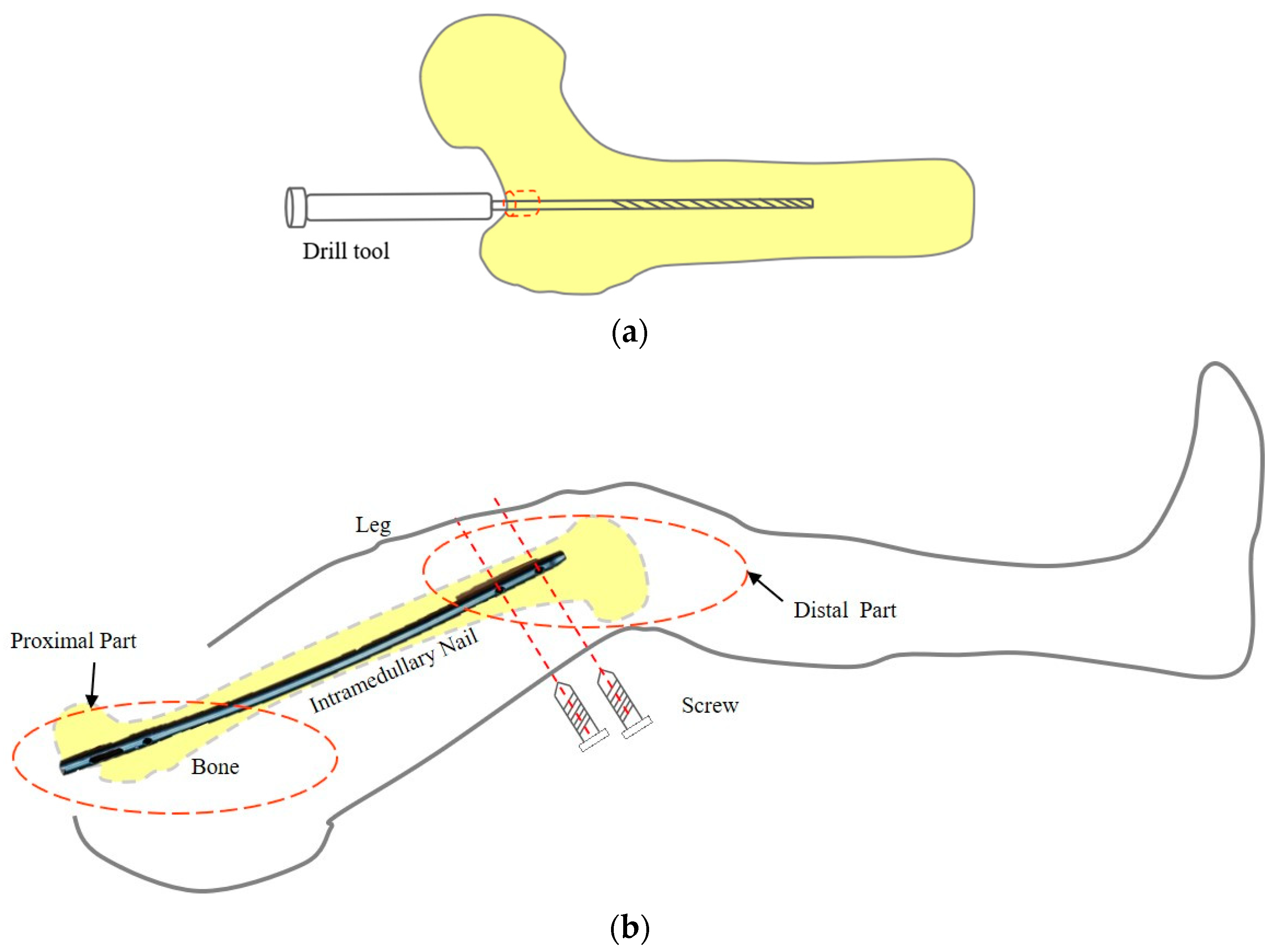
Figure 1. Concept on distal screwing. (a) Window-making for insertion of a guide wire. (b) Distal fixation with screws.
Applsci 11 11109 g001
Figure 2. Procedure of drilling device guidance.
Applsci 11 11109 g002
Figure 3. Proposed fine adjustment device. (a) 3D model (b) Fabricated prototype.
Applsci 11 11109 g003
Figure 4. Guiding pattern block of the fine adjustment device. (a) 3D model. (b) Fabricated prototype (red dotted lines added for the visualization). (c) X-ray image of hole jig.
Applsci 11 11109 g004
Figure 5. The procedure of alignment between the C-arm and FAD. (a) The initial state of the C-arm and FAD. (b) Rough alignment to place the PGSLP within range of the X-ray. (c) Translation adjustment to move the laser image near the center of the C-arm panel. (d) Rotation adjustment to make the two planes parallel.
Applsci 11 11109 g005
Figure 6. Confirmation of position of the two holes relative to each other. (a) Misaligned state. (b) Aligned state.
Applsci 11 11109 g006
Figure 7. Experimental setup. (a) Whole setup. (b) Enlarged.
Applsci 11 11109 g007
Figure 8. Measurement of angle error by OTS marker.
Applsci 11 11109 g008
Figure 9. Definition of translational error. (a) Conceptual diagram. (b) Real X-ray image overlaid by colored circles.
Applsci 11 11109 g009
Figure 10. X-ray images before and after fine adjustment. (a) Misaligned state. (b) Aligned state.
Applsci 11 11109 g010
Table 1. Measured parameters during experiments.
SubjectIndexParallelization Time (s)Fine Positioning Time (s)Total Time
(s)
No. of X-ray Images (EA)X-ray Exposure
(cGy-cm2)
S1T17214521761.14
S1T216336352102.71
S1T352342394103.67
S2T45131036172.94
S2T52720523262.58
S2T63123826992.66
S3T72714016761.22
S3T8638114431.00
S3T931649531.31
Average ± STD41.1 ± 19.0207 ± 107248 ± 1056.67 ± 2.652.14 ± 0.97
Table 2. Tilted angle error in the parallelization step and translational error in the fine-positioning step.
IndexT1T2T3T4T5T6T7T8T9Average ± STD
Tilted angle error (°)0.9501.201.010.2800.2002.152.181.641.511.24 ± 0.715
Translational Error (mm)0.1500.3900.3900.2400.4000.4700.3800.5600.4200.378 ± 0.120
Publisher’s Note: MDPI stays neutral with regard to jurisdictional claims in published maps and institutional affiliations.