1. Introduction
The large deformation, caused by earthquake liquefaction, will endanger the stability of nearby rivers and the environment of formation slopes. Liquefaction caused by earthquakes often leads to the loss of bearing capacity of the foundation and endangers the safety of structures built on the liquefiable soil (Xu et al. [
1]). Furthermore, liquefaction tends to weaken the saturated sand and produce even greater deformations.
According to the post-earthquake survey by Bennett [
2], Treasure Island had 34 sand boil sites and 28 sites with surface subsidence following the 1989 Loma Prieta earthquake in California, USA. In 1999, the Kocaeli earthquake in Turkey triggered large-scale liquefaction in the Izmit Bay area (Sonmez et al. [
3]), and 20% of the low-rise concrete houses, as well as 56% of the low-rise brick-timber houses in Adapazari were severely damaged or destroyed due to foundation liquefaction (Cetin et al. [
4]). Werner et al. [
5] reported seismic damage to the port structure of Port-Au-Prince during the 2010 Haiti earthquake and pointed out that large-scale liquefaction and lateral spreading of soil near the port caused different degrees of lateral movement of bridge pile foundations and abutments. Haskell et al. [
6] investigated the damage to pile foundation during the 2011 Christchurch earthquake in New Zealand and found that the lateral spreading of liquefiable soil damaged pile foundation. More recently, Zhou et al. [
7] studied liquefaction cases in the Wenchuan Earthquake in China in 2008 and reported damage by seismic liquefaction and lateral displacement of pile foundation in Yingxiu Town. The case of the city of Catania, in South-Eastern Sicily (Italy), is subjected to high seismic hazards. In particular, seismic liquefaction phenomena were reported by historical sources following the 1693 (MS =7.0–7.3, Io = X-XI MCS) and 1818 (MS = 6.2, Io = IX MCS) strong earthquakes (Grasso and Maugeri [
8]; Grasso et al. [
9]).
Through comparing the damages discussed in the above studies, we noticed that the liquefaction-induced loss of bearing capacity of the foundation, along with the lateral extension of soil, will aggravate the seismic damage to structures. In view of the damage caused by liquefaction of foundation during earthquakes, foundation reinforcement, with gravel piles and anti-liquefaction measures, is an important research direction.
In recent years, in order to eliminate liquefaction hazards, a variety of foundation treatment methods have been developed, among which gravel piles in reinforced foundation have the best effect (Poorooshasb et al. [
10]), and can be used to reinforce weak foundations such as embankments (Zhao et al. [
11]). Therefore, gravel piles have been widely used in the treatment of weak subgrades such as those in highways, railways, and large petrochemical field stations.
A field investigation found that a foundation treated by gravel piles for anti-liquefaction was undamaged during the Loma Prieta earthquake in 1989 (Mitchell and Wentz, [
12]). Meanwhile, a field investigation, conducted after the Great East Japan Earthquake of 2011, showed that no damage was found in the foundation treated by gravel piles (Yasuda et al. [
13]), even though this earthquake resulted in large-scale liquefaction in the coastal area of Tokyo Bay. Based on 24 case analyses of stone columns reinforcement, Salem et al. [
14] pointed out that gravel piles could greatly improve the weak foundation’s resistance to liquefaction.
In terms of test model research, laboratory tests found that the application of stone columns and granular blankets significantly increased the ultimate bearing capacity of soft foundations (Nazariafshar et al. [
15]). Shaking table tests, conducted on the four foundations stabilized with stone columns, found that the stone columns had a significant mitigation effect on soil liquefaction during earthquakes (Huang et al. [
16]). With the increase in seismic acceleration under high seismic intensity, the anti-liquefaction performance of the composite foundation stabilized with stone columns was obvious in shaking table model tests (Qu et al. [
17]). Wang [
18] found that gravel piles reduced the amplitude of the peak pressure, caused by piling, and quickly dissipated the excess pore water pressure in the liquefiable layer. Based on the results of 1 G laboratory-scale shaking table tests, Dinh et al. [
19] showed that the compaction and drainage effects of gravel piles were the main factors to reduce the liquefaction of the foundation.
The compaction of weak foundation by gravel piles not only improved the deformation modulus and bearing capacity but also promoted the rapid dissipation of dynamic pore pressure because of the drainage effect in permeable gravel piles. In this way, the likelihood of liquefaction was greatly reduced.
According to theoretical and numerical evaluations, the bearing capacity of soft clay soil, which has been improved through stone columns, with both static and earthquake load effect reinforced with the increase in the diameter and depth of the stone column (Şahinkaya et al. [
20]). Moreover, laboratory tests and numerical simulations found that the bearing capacity ratio increased, and the settlement reduction factor decreased upon increasing the number and length of stone columns (Chenari et al. [
21]). Zou et al. [
22] pointed out that stone columns, in saturated sandy soils, could significantly improve the soil’s resistance to liquefaction through the dynamic response. Meanwhile, Amrendra Kumar et al. [
23] performed a numerical analysis on shallow foundations underlain by a stone column, and found that the granular column could effectively mitigate liquefaction.
Suravi Pal et al. [
24] provided a mathematical model for determining the drainage capacity of stone columns, considering their stiffness and limited permeability, during liquefaction. Their modeling results indicated that the soil’s susceptibility to liquefaction would increase with the reduction in the stiffness and permeability of the stone column. A three-dimensional finite element method was employed to simulate a centrifuge experiment; in this simulation, if the permeability of stone columns exceeded a threshold, the liquefaction hazard dramatically decreased in a silty sand foundation (Tang et al. [
25]). Furthermore, Lu et al. [
26] showed that using stone columns was an effective way to mitigate lateral deformation in uniform and stratified liquefiable soil strata. The seismic response of the coupled soil-structure system has been further examined in terms of peak bending moments along the pile foundation, emphasizing the possibility of a kinematic interaction on piles induced by the seismic action (Castelli et al. [
27]).
Wang et al. [
28] deduced the analytical solution of consolidation between gravel piles and soil suffered the variable load, based on the premise of considering the influence of replacement ratio and modular ratio between gravel pile and soil. In view of the lateral expansive deformation of gravel piles in composite foundation, Zhang et al. [
29] proposed an analytical solution of settlement in composite foundation, reinforced with gravel piles. Based on the dynamic constitutive model of sand, a dynamic numerical analysis was performed for gravel pile reinforcement in the South-to-North Water Diversion Project; the excess pore pressure of saturated sand foundation at the bottom of the main canal were obviously reduced due to the drainage effect of gravel piles (Yang et al. [
30]). Adopting gravel piles, Yang et al. [
31] carried out a loading plate test and a super-heavy dynamic penetration in situ test and evaluated the bearing capacity and liquefaction resistance in treatment subgrade. Moreover, to reduce the liquefaction hazards, in the stratigraphic environment of saturated sand, at the Yinping hydropower station, Li [
32] used gravel piles to reinforce the liquefiable foundation, in the context of a large area and depth, but at a high cost.
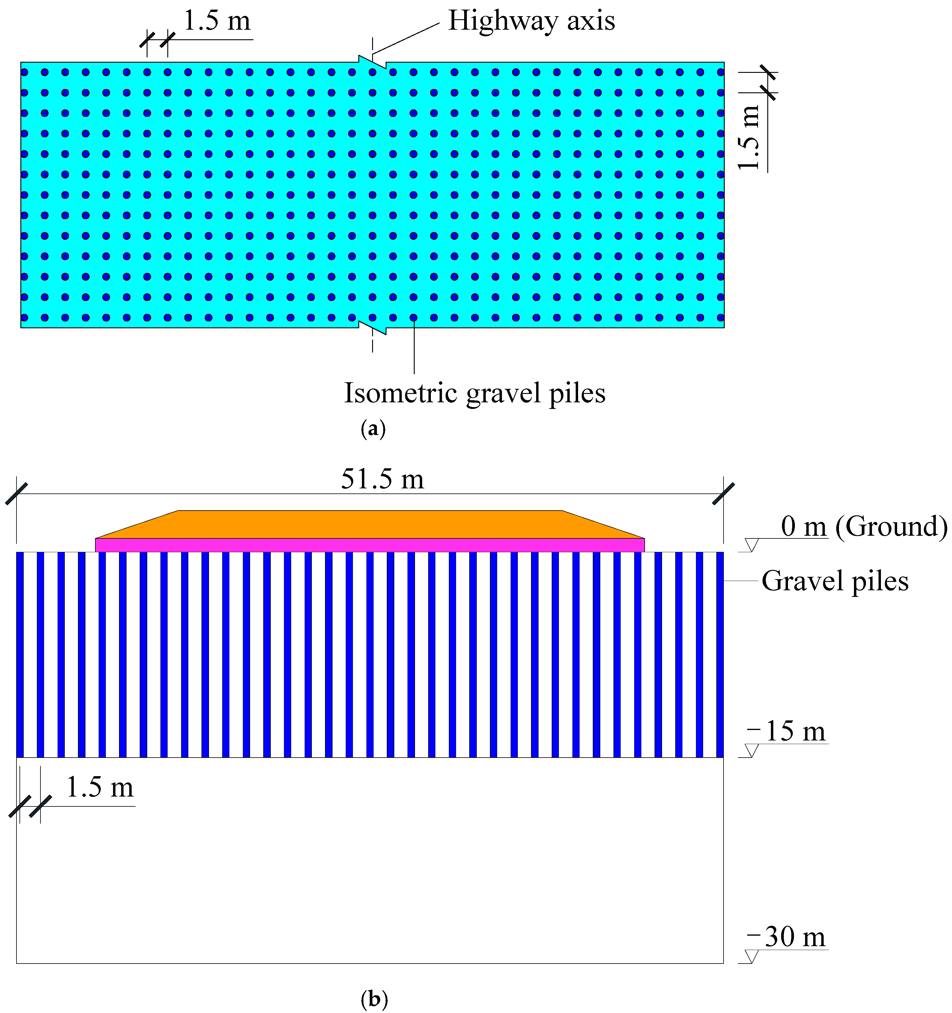
However, it should be noted that many of the above analyses are, essentially, based on a treatment scheme of gravel piles or stone columns. This scheme is referred to as isometric gravel piles, in this paper, and it is illustrated in
Figure 1.
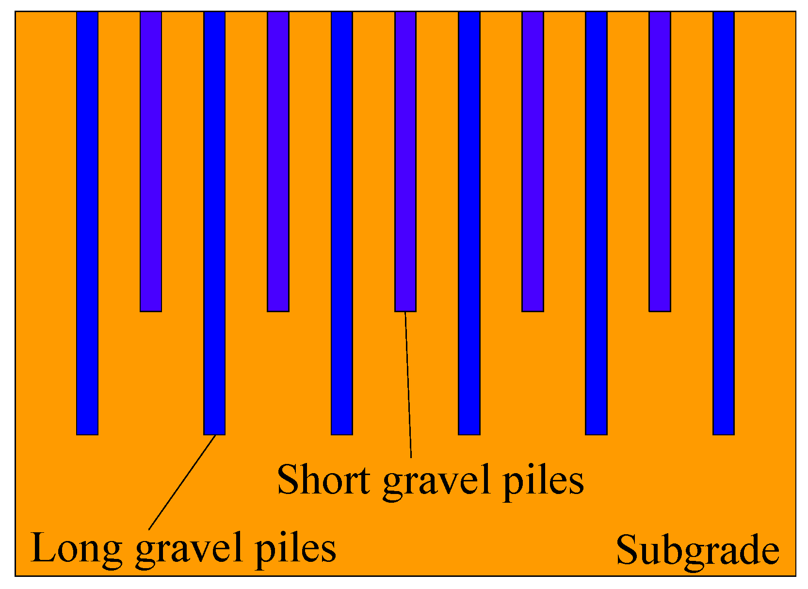
Although isometric gravel piles can improve the bearing capacity and anti-liquefaction ability of soft foundation, their implementation may lead to higher construction costs. Therefore, implementing a combination of long-short gravel piles has been discussed. This scheme is referred to as interphase gravel piles in this paper, and it is shown in
Figure 2.
The load-bearing characteristics of the long-short piled raft foundation and the interaction mechanism between piles and soil were analyzed, and the results showed that anti-liquefaction and control of settlement could be achieved with such piles (Chen et al. [
33]). Liu et al. [
34] studied, via numerical simulations, the response of a rocking foundation that was founded in a soft clayey environment and reinforced by stone columns, and they found that the length of the short pile in long-short gravel piles had little effect on the load bearing capacity of soft soil foundation. Meanwhile, Zhao et al. [
35] discussed the anti-liquefaction mechanism of long-short piles in the vibro-replacement stone column composite foundation and pointed out that there was no need for a large number of long gravel piles to reduce the excess pore water pressure in deep soil. According to the layout of the long-short gravel piles used in these studies, these long-short gravel piles are the interphase long-short gravel piles referred to in this paper. Although the pile interphase long-short gravel piles also have the effect of anti-liquefaction, because of the long total pile length and more pile materials, the project cost is higher.
In summary, existing studies have mainly evaluated the performance of the gravel pile in improving the bearing capacity and anti-liquefaction capacity of foundation, but they have ignored the corresponding increases in engineering costs. In order to make gravel piles play a significant role in improving resistance to liquefaction, it is crucial to put forward a more effective, and cost-efficient, treatment method for anti-liquefaction in the deeply deposited saturated liquefiable soil.
2. Presentation of a New Reinforcement Scheme
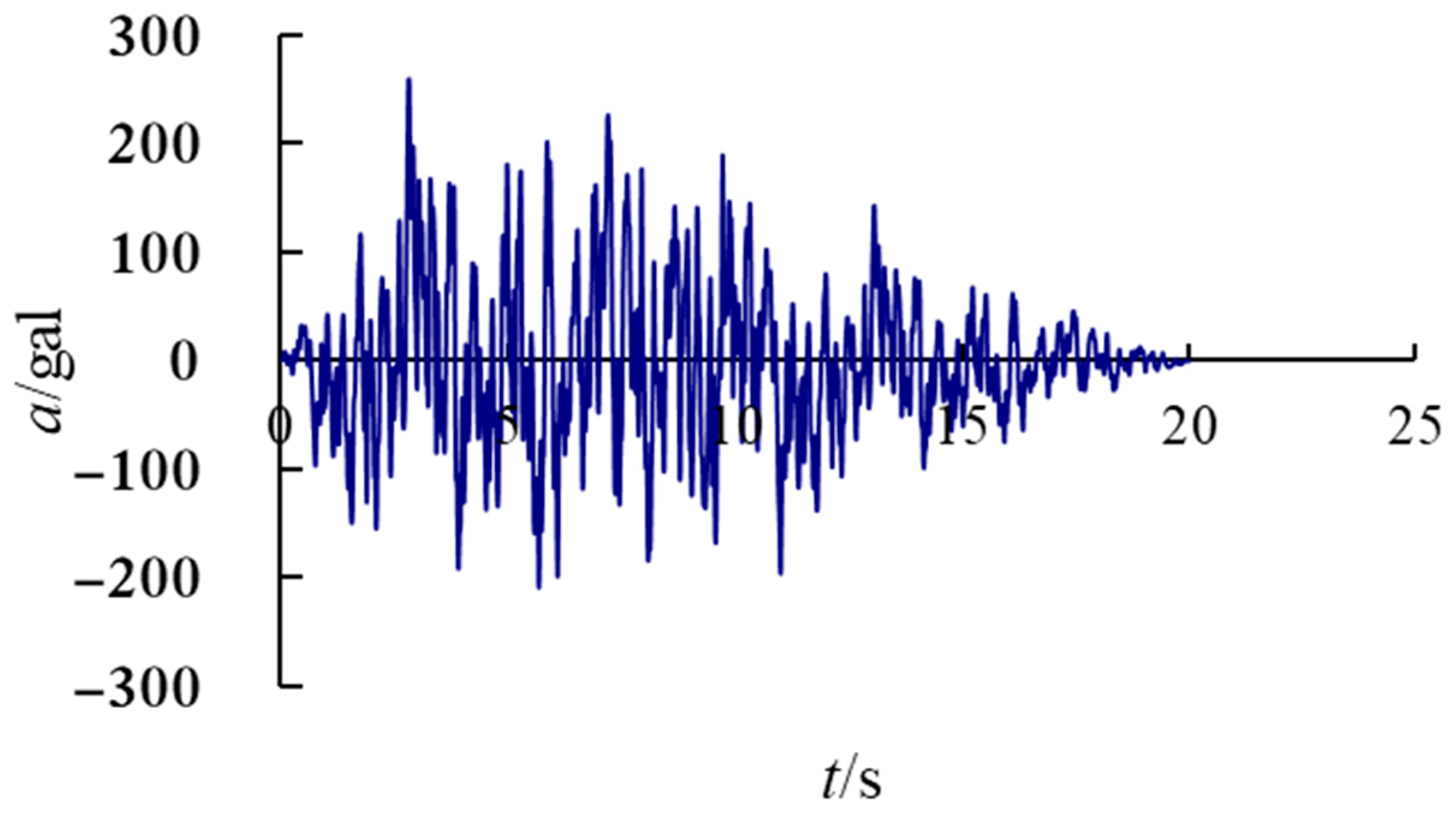
Aksu-Kashgar highway is a new high-grade highway running through Aksu, Atush, and Kashgar in China, which passes through three prefectures, with a total length of 428.49 km. The peak value of ground motion acceleration in this area is about 260 gal, and the corresponding seismic intensity zoning is VIII. The geological condition is alluvial fan plain landform, the main stratum is quaternary silt layer, and the main adverse geology is sandy soil liquefaction, saline soil and collapsible silt. The subgrade silt layer in this section is thicker, all of which exceed 30 m. Section AK-3 is a bid section of the Aksu-kashgar highway, and it consists of four sections 680 m of 1334.67 km~1335.35 km, 660 m of 1414.38 km~1415.04 km, 4270 m of 1415.73 km~1420 km, and 870 m of 1398.43 km~1399.3 km. According to the design drawings, the main line of section AK-3 of the Aksu-kashgar highway has 15.8 km dynamic compaction subgrade, and the auxiliary line has 3.2 km dynamic compaction subgrade. According to the analysis of dynamic compaction test results, for the thick and seriously liquefied sand layer, dynamic compaction construction cannot effectively improve the liquefaction of this section, which is easy to cause adverse disturbance to the soil. If effective foundation treatment measures are not taken, it will not be possible to ensure whether it can be put into use in the future.
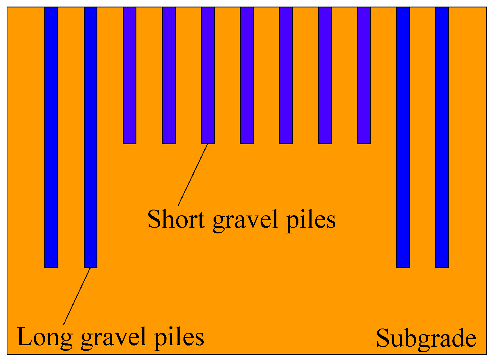
Since the liquefaction hazards in the deeply deposited saturated liquefiable soil, in Aksu-kashgar highway in China, could not be resolved after the dynamic compaction of subgrade, an effective and economical new anti-liquefaction scheme must be proposed. This scheme is called subarea long-short gravel piles. It is proposed to save on the consumption of gravel piles while still achieving the anti-liquefaction goal. This scheme is illustrated in
Figure 3.
However, this scheme has rarely been evaluated through elastoplastic dynamic coupling consolidation, based on the generalized plastic Pastor–Zienkiewicz III dynamic constitutive model and Biot’s dynamic consolidation theory.
The Pastor–Zienkiewicz III constitutive model (Paston et al. [
36]) is an elastic–plastic dynamic constitutive model, and it can simulate the vibration compaction characteristics of sand under drainage conditions. It can also simulate the liquefaction of saturated sand and is, therefore, is a practical constitutive model for soil deformation characteristics analysis and geotechnical dynamic calculations.
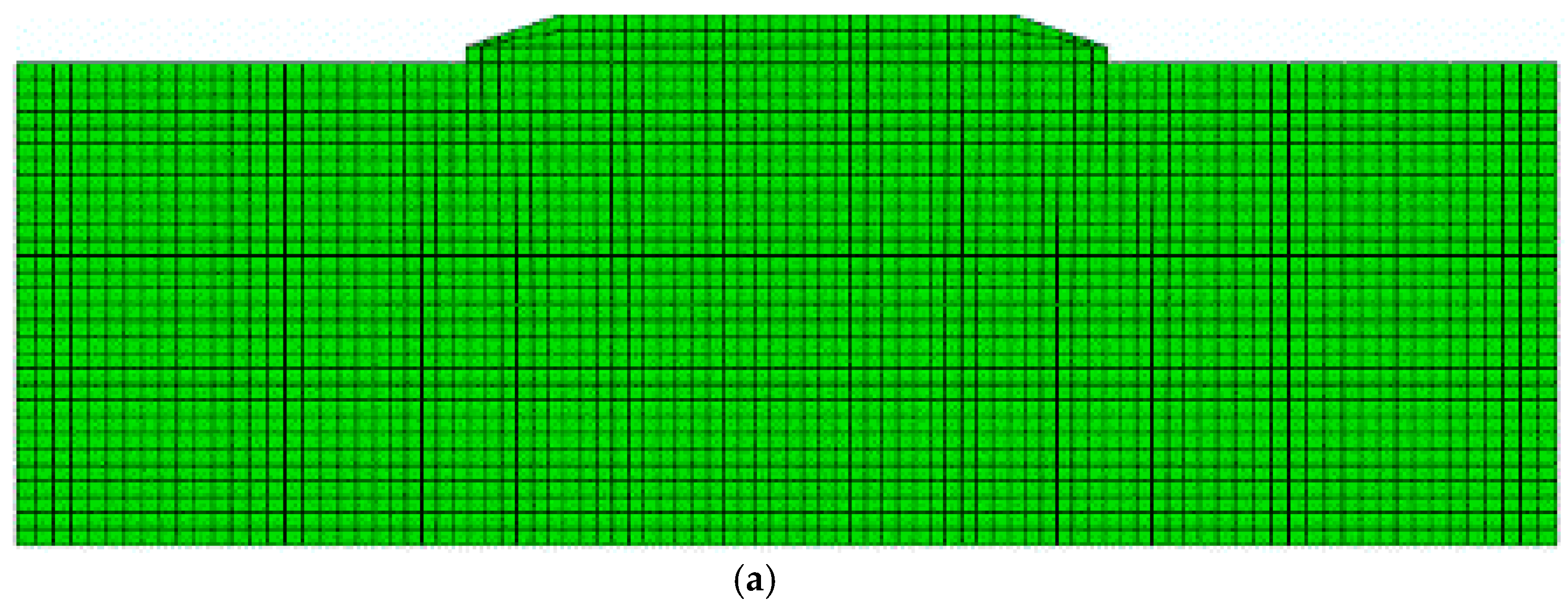
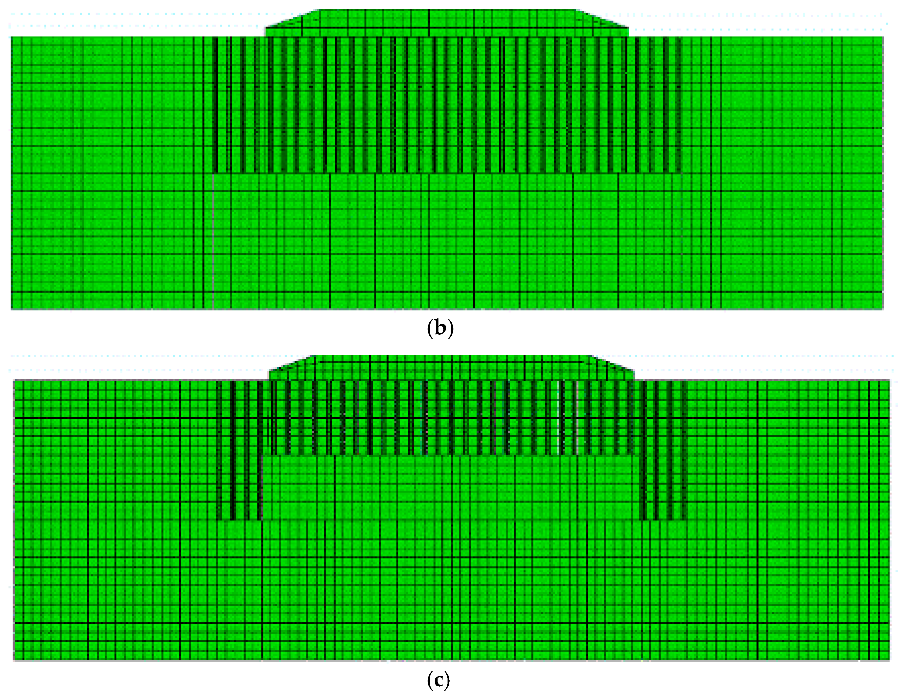
In order to address the potential threat of embankment instability resulting from liquefaction in the Aksu-kashgar highway (which is currently under construction), we compared the merits and demerits of the implementation of the two different reinforcement schemes. This first scheme is of the conventional isometric gravel piles scheme, and the other is the subarea long-short gravel pile scheme. The seismic subsidence, the distribution of dynamic pore pressure, and excess pore pressure ratio were analyzed under the conditions of natural foundation and the two reinforcement schemes. We used the finite element program FEMEPDYN, based on the Pastor–Zienkiewicz III model and the coupled dynamic consolidation theory.
3. Limitations of Dynamic Compaction in Foundation Treatment
Section AK-3 of the Aksu-kashgar highway in China is 151.482 km in length. The main stratum is weak foundation with a deposition thickness of 30.0 m, the upper layer is sandy soil with a thickness of 15.0 m, and the lower layer is silt, which also has a thickness of 15.0 m. There are more than 50 irrigation ditches crossing the roadbed near the highway, and there are three reservoirs with water levels higher than the original surface of the roadbed, all year round, on the left side of the roadbed. These two factors result in the long-term saturated state of the highway’s foundation. According to Chinese regulations Code for Seismic Design of Buildings, the peak acceleration of section AK-3 of the Aksu-kashgar highway is 260 gal and the seismic intensity is relatively large in the region. Thus, the highway embankment is faced with liquefaction hazards in the event of an earthquake.
Through anti-liquefaction testing in the natural foundation of the Section AK-3, we found that the liquidity index (LI) varied from 17.2 to 27.4 at a depth of 8.0 m. These values correspond to moderate and severe liquefaction grades, and the natural foundation cannot meet the design requirements of anti-liquefaction.
To improve the anti-liquefaction capacity of the weak foundation, the zone with the severe liquefaction grade in Section AK-3 was stabilized with dynamic compaction (i.e., compacted two times with an impact energy of 2000 kN·m). The liquidity indices at a depth of 8.0 m, after dynamic compaction, are shown in
Table 1.
These extensive tests showed that the effective depth of reinforcement through dynamic compaction (with an impact energy of 2000 kN·m) is within the range of 5.0 to 6.0 m. However, dynamic compaction may not solve the problem of seismic liquefaction in the deeply deposited saturated liquefiable soil. Therefore, the highway subgrade will still face liquefaction hazards associated with earthquakes.
5. Results
5.1. Comparative Analysis of Seismic Subsidence Based on Elastic–Plastic Dynamic True-Coupled Consolidation
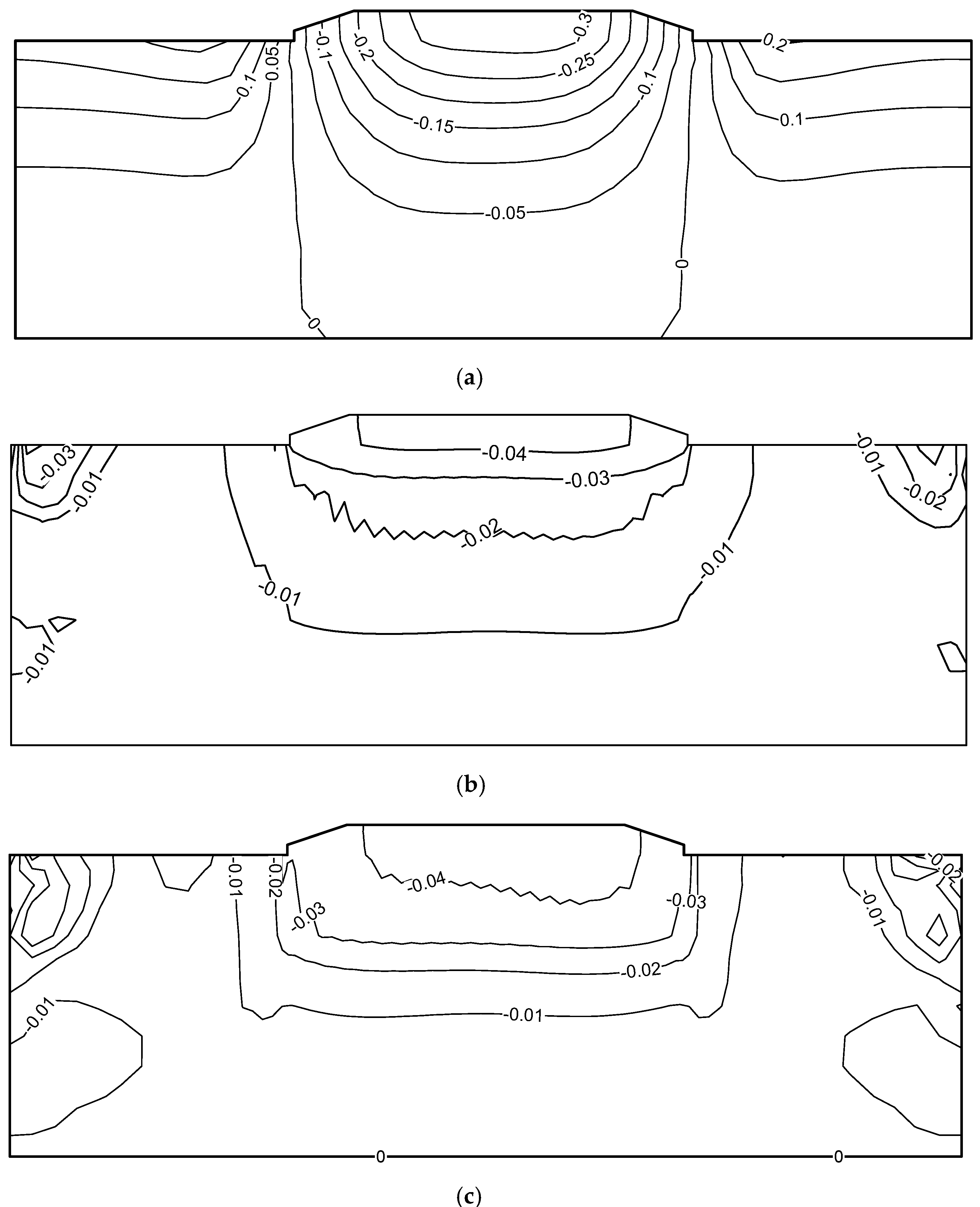
In the later period of the earthquake, the subsidence distribution of the natural foundation, foundation reinforced with isometric gravel piles, and foundation reinforced with subarea long-short gravel piles are as shown in
Figure 8a–c, respectively. In natural foundation, the earthquake resulted in an uplift of 0.20 m in surface sand near both sides of the embankment; this was accompanied with a seismic subsidence of 0.30 m in the midsection of the roadbed. In the foundation reinforced with isometric gravel piles, there was no obvious deformation of the soil on either side of the roadbed; however, the seismic subsidence in the midsection of the roadbed was sharply reduced to 0.04 m. Meanwhile, in the foundation reinforced with subarea long-short gravel piles, the seismic subsidence in the midsection of the roadbed was sharply reduced to 0.045 m.
Compared with the natural foundation, the seismic subsidence of the foundation reinforced with isometric gravel piles was reduced by 86%, and that of the foundation reinforced with subarea long-short gravel piles was reduced by 85%. In the two reinforcement schemes, the uplift problem observed in the surface soil on both sides of the roadbed was basically eliminated. The reduction in seismic subsidence was remarkable, and both reinforcement schemes could effectively control the seismic subsidence. However, it is worth noting that the pile consumption of isometric gravel piles scheme is obviously greater than that of subarea long-short gravel piles scheme.
5.2. Comparative Analysis of Pore Pressure during Earthquake Based on Elastic–Plastic Dynamic True-Coupled Consolidation
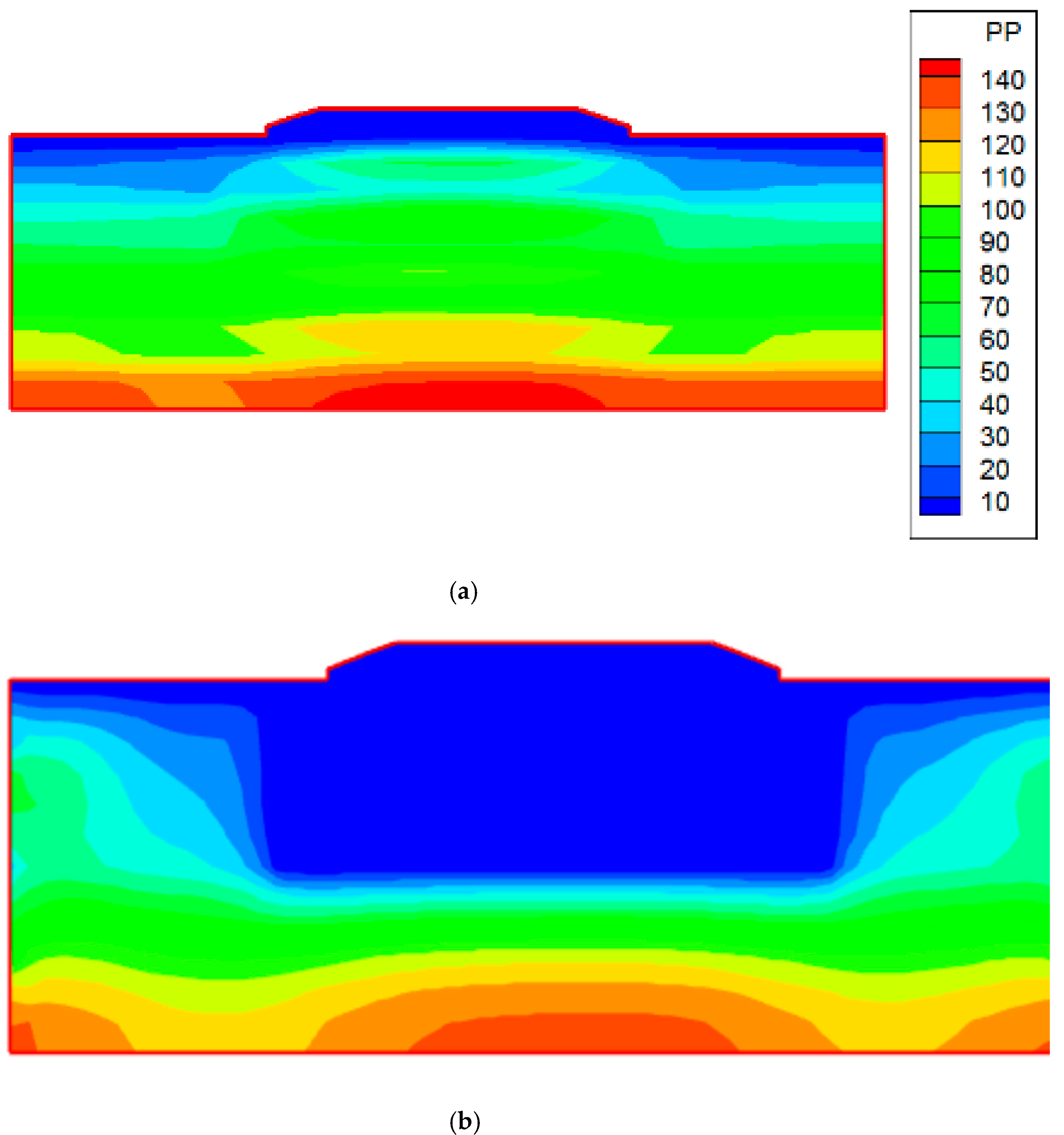
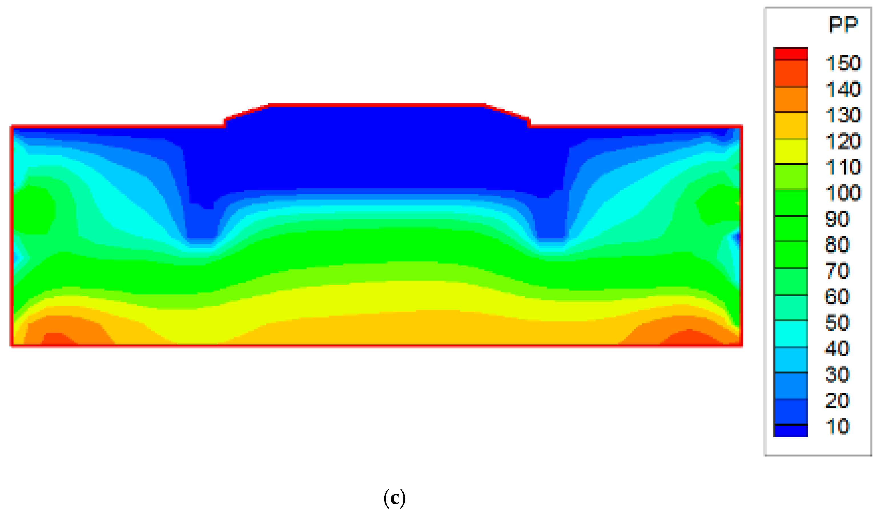
Twenty seconds into an earthquake, the dynamic excess pore water pressure distribution in natural foundation, foundation reinforced with isometric gravel piles, and foundation reinforced with subarea long-short gravel piles in the deeply deposited saturated liquefiable soil are shown in
Figure 9a–c, respectively.
In natural foundation, the dynamic excess pore pressure in saturated sand increased significantly during the earthquake; moreover, the maximum pore pressure reached about 88.0 kPa at a depth of 8.0 m in the midsection of the roadbed. Thus, the potential for liquefaction increased greatly. In the foundation reinforced with isometric gravel piles, the dynamic excess pore pressure, at a depth of 5.0 m in the midsection of the roadbed, was sharply reduced to 4.0 kPa; meanwhile, in the foundation reinforced with subarea long-short gravel piles, the dynamic excess pore pressure at the same position was sharply reduced to 5.0 kPa.
Compared with the natural foundation, the dynamic excess pore pressure in the foundation reinforced with isometric gravel piles was reduced by 95%, and the foundation reinforced with subarea long-short gravel piles was reduced by 94%. The reduction in dynamic excess pore pressure was remarkable in both reinforcement schemes. Both reinforcement schemes could effectively control the dynamic excess pore pressure during the earthquake, and thus, the liquefaction in the stratigraphic environment of saturated sand could be greatly reduced.
However, it is still worth noting that the pile consumption of the isometric gravel piles scheme is obviously greater than that of the subarea long-short gravel piles scheme.
5.3. Comparative Analysis of Time Histories of Dynamic Pore Pressure Based on Elastic–Plastic Dynamic True-Coupled Consolidation
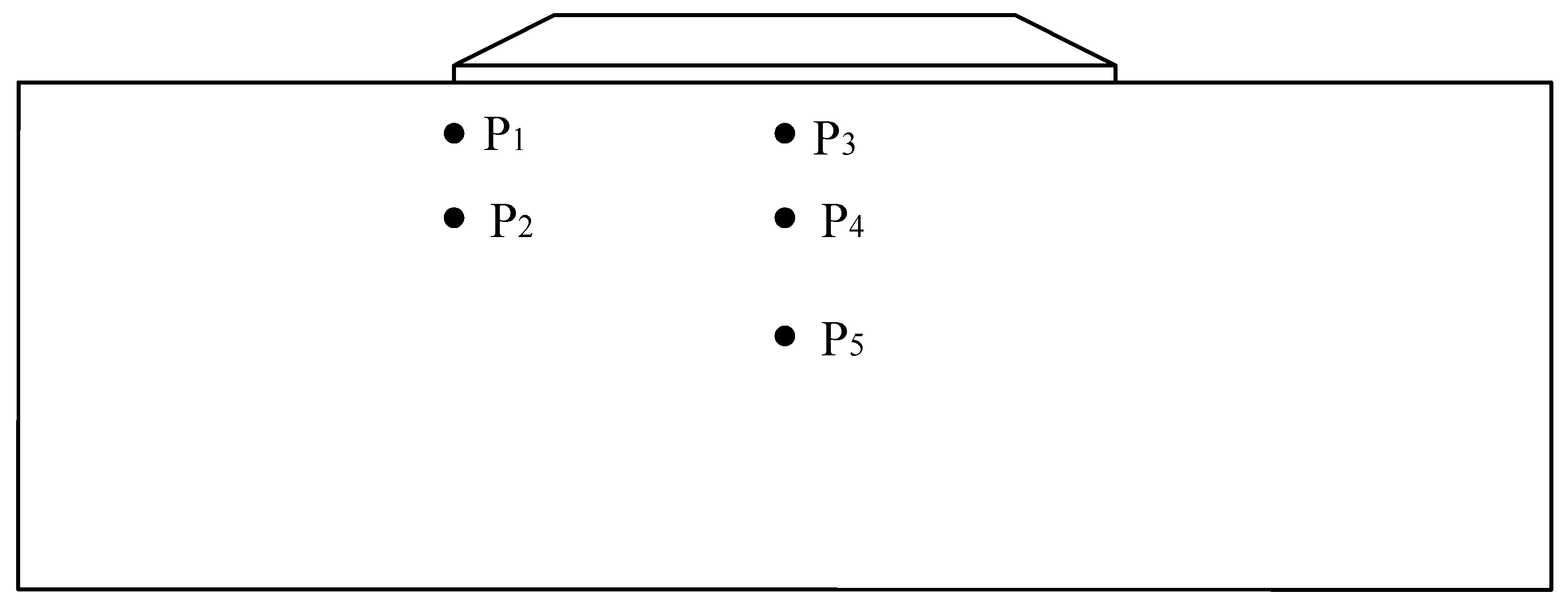
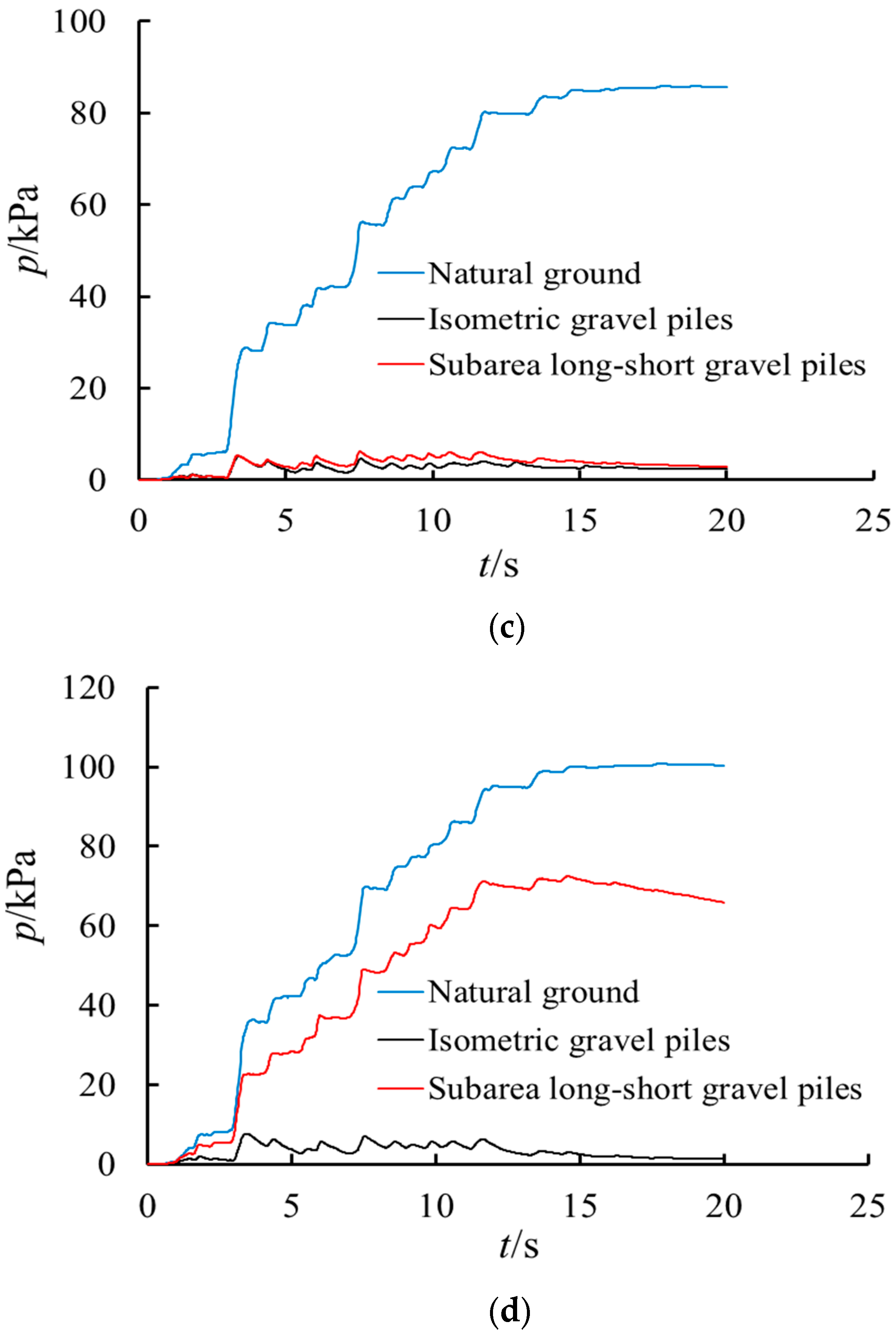
In order to analyze the time histories of dynamic excess pore water pressure, two observation points, P1 and P2, were selected at depths of 3.0 m and 8.0 m, respectively, below the left edge of the embankment. Then, three observation points, P3, P4, and P5, were selected at depths of 3.0, 8.0, and 15.0 m, respectively, in the middle of the subgrade. The observation points and their placements are shown in
Figure 10.
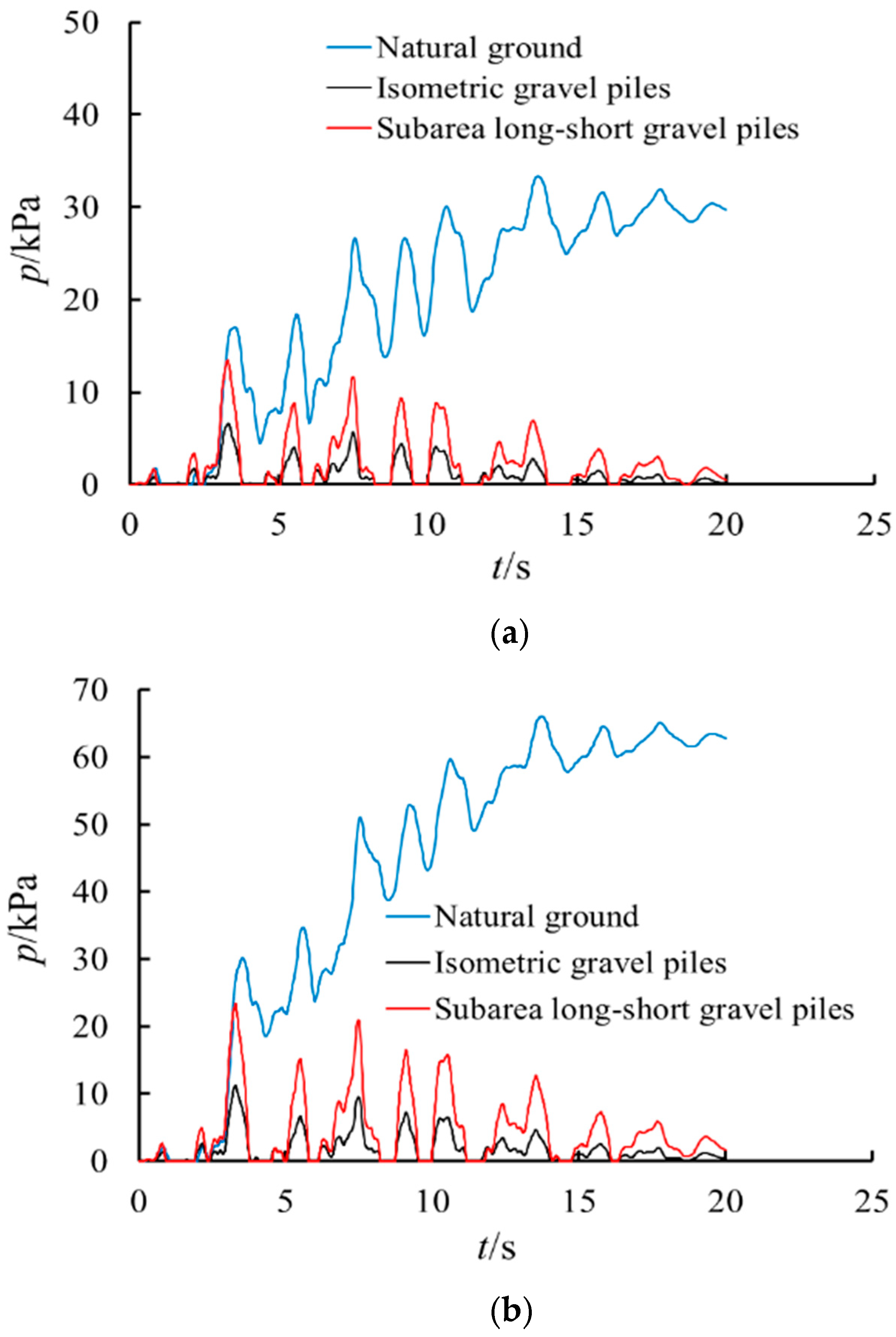
The time histories of dynamic excess pore water pressure in natural foundation, foundation reinforced with isometric gravel piles, and foundation reinforced with subarea long-short gravel piles, in the deeply deposited saturated liquefiable soil during an earthquake, are shown in
Figure 11.
During seismic activity, the dynamic excess pore water pressure of the deeply deposited saturated subgrade increased significantly. The excess pore water pressure, in the initial stage of the earthquake, increased sharply and was close to the peak, and it would dissipate in the later stage of the earthquake in the long term.
Compared with the natural foundation, the dynamic excess pore water pressure in the foundation reinforced with isometric gravel piles and in the foundation reinforced with subarea long-short gravel piles were reduced significantly at depths of 3.0 m and 8.0 m in subgrade. The dynamic excess pore pressure dissipated quickly, due to the drainage effect in gravel piles, after it reached its peak value. This comparison proved the effectiveness of the two reinforcement schemes once again.
It is worth examining the dynamic pore pressure at the depth of 15.0 m (see
Figure 11d). The dynamic excess pore pressure at P5 in the natural foundation increased sharply and was close to the peak during the earthquake; conversely, the foundation reinforced with isometric gravel piles increased only slightly and then dissipated rapidly. Furthermore, the accumulation of excess pore pressure at P5 in the foundation reinforced with subarea long-short gravel piles was obviously slower than that at P5 in natural foundation; meanwhile, the dissipation of dynamic excess pore pressure was faster in the foundation reinforced with subarea long-short gravel piles at P5.
Although the dynamic excess pore water pressure, at the depth of 15.0 m in the subarea long-short gravel piles scheme, is larger than that in the isometric gravel piles scheme, the threat of liquefaction can be judged by the distribution of dynamic excess pore water pressure in both schemes.
6. Discussion
The dynamic excess pore pressure ratio can reflect the liquefaction distribution in the deeply deposited saturated liquefiable soil during earthquakes. When the ratio reaches about 1.0, the saturated soil will be in the state of liquefaction failure.
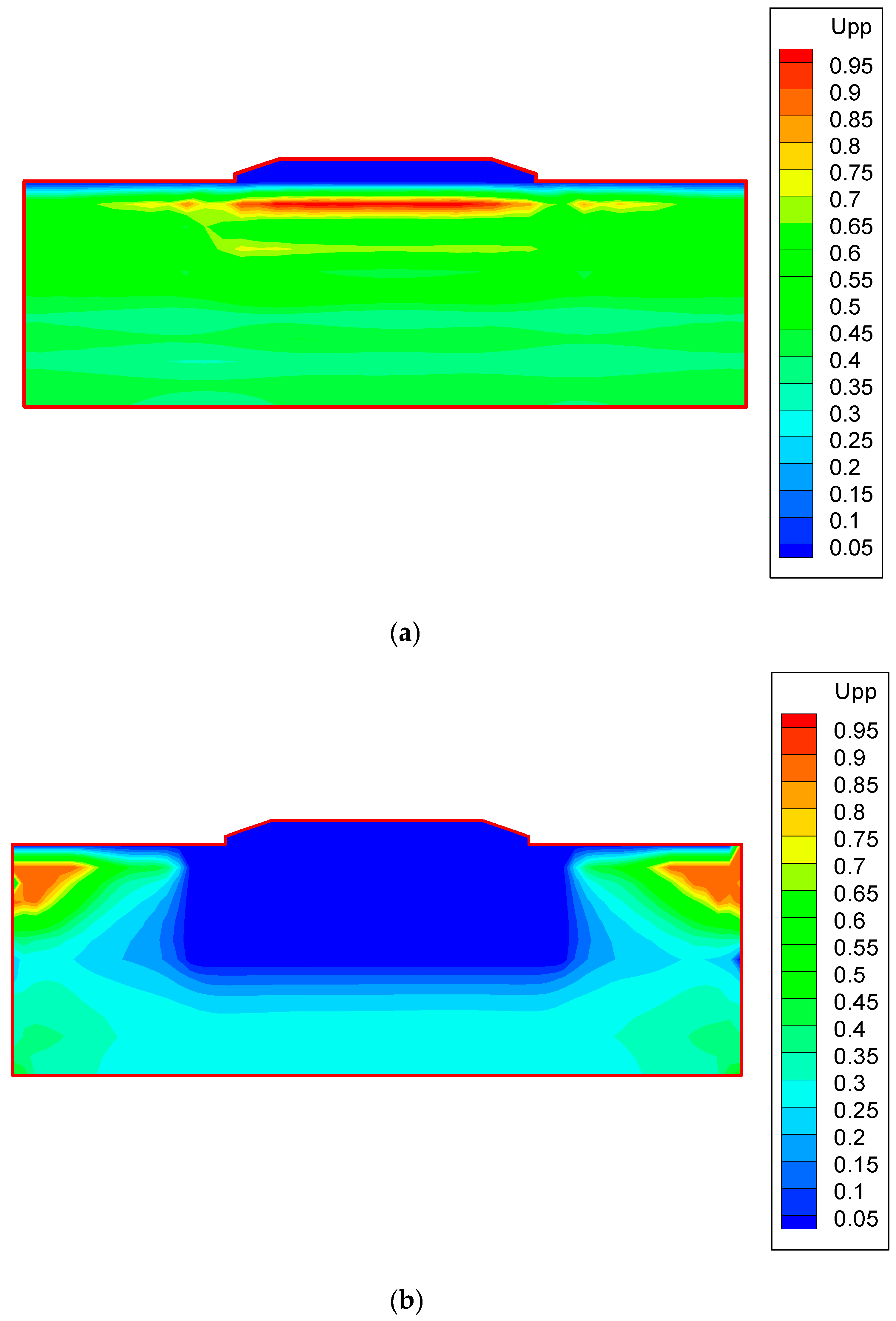
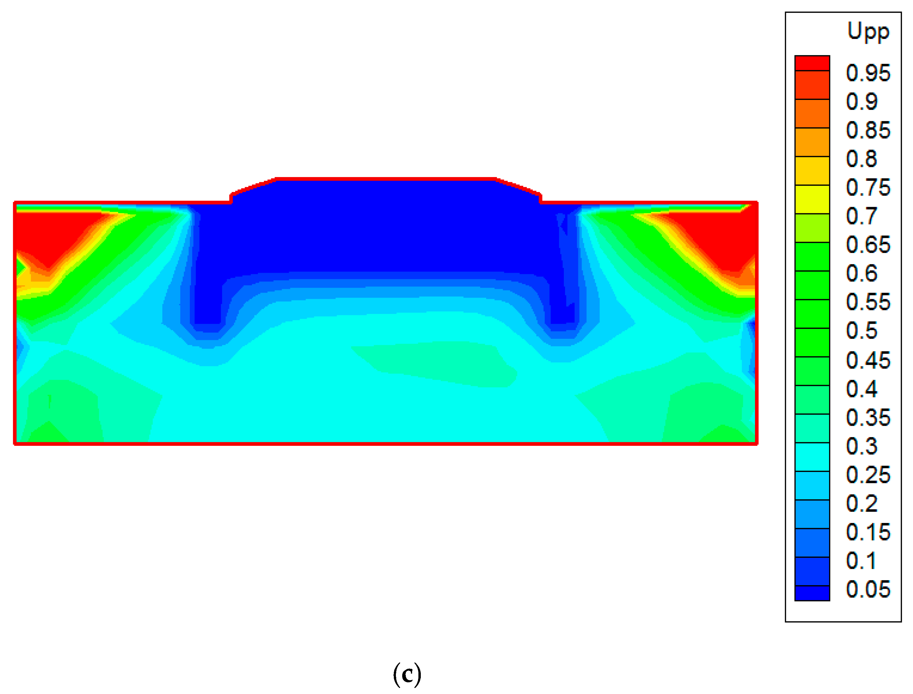
Twenty seconds into the earthquake, the distribution of the excess pore pressure ratio in natural foundation, foundation reinforced with isometric gravel piles, and foundation reinforced with subarea long-short gravel piles are as shown in
Figure 12a–c, respectively.
The excess pore pressure ratio in the upper soil of natural foundation was close to 1.0, which indicated that the subgrade was about to be in the state of liquefaction failure. The dynamic excess pore pressure ratio of the subgrade soil was less than 0.15, at a depth of 23.0 m, in the foundation reinforced with isometric gravel piles. Besides, for the foundation reinforced with subarea long-short gravel piles, the dynamic excess pore pressure ratio of the subgrade soil was less than 0.15, at a depth of 22.0 m, in both sides of the roadbed and at a depth of 13.0 m in the midsection of roadbed. Therefore, neither reinforced foundation would be liquefied because the dynamic excess pore pressure ratio at the core of the subgrade is far less than 1.0.
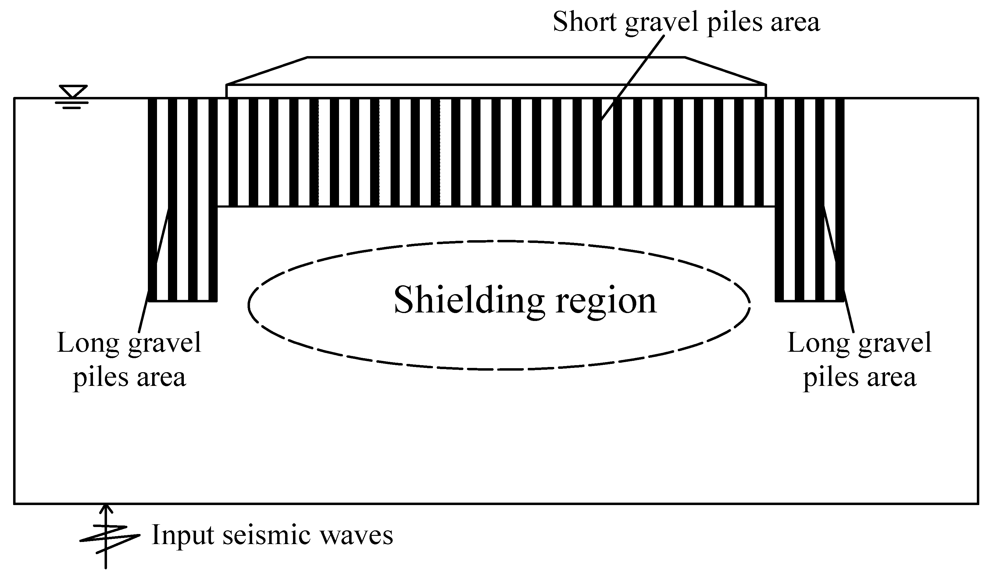
In the foundation reinforced with subarea long-short gravel piles, a special shielding region, where excess pore water pressure decreased significantly because of the drainage effect in the permeable gravel piles, could be formed between the long gravel piles on the sides of the roadbed and below the short pile in the midsection of the roadbed. This is shown in
Figure 13. The long gravel piles on the sides could block the propagation of seismic waves, and the drainage effect of gravel piles resulted in a large dissipation in the dynamic pore pressure around the long gravel piles. At the same time, the increase in excess pore pressure in the midsection could be restrained in the shielding region, below the short gravel piles, through their own drainage actions.
The excess pore pressure ratio in the shielding region was obviously smaller than that in the same region in natural foundation; therefore, the shielding region must be in the state of non-liquefaction. With the shielding effect, implementation of the foundation reinforced with subarea long-short gravel piles not only greatly reduced the level of excess pore pressure ratio in the shielding region, but it also greatly reduced the length required for gravel piles below the middle of the embankment. In addition, the project’s cost can be effectively reduced by using only a few long gravel piles, arranged under the embankment sides, and a large number of short gravel piles arranged beneath the middle of the embankment.
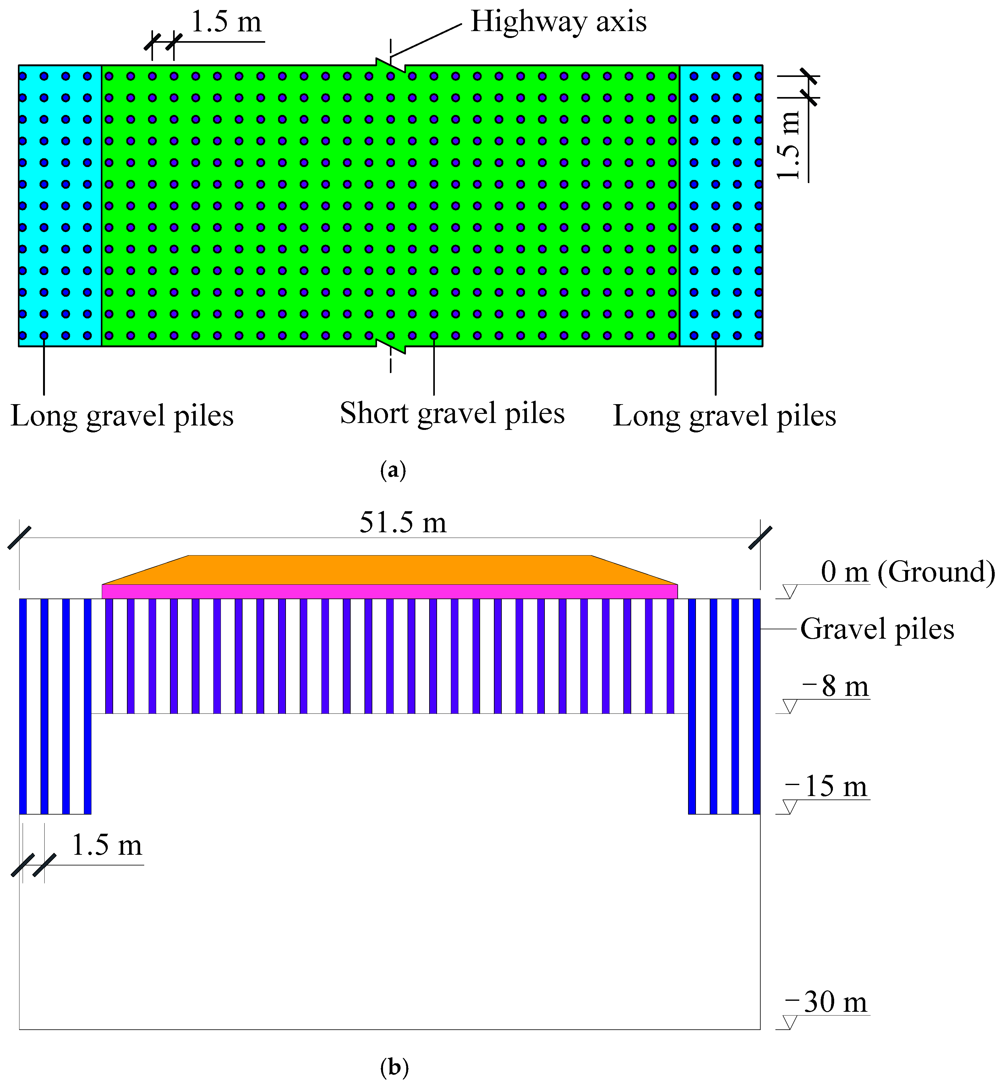
In terms of engineering costs, according to
Figure 4 and
Figure 5, the total length of gravel piles, used in the isometric gravel piles scheme, is 525 m, while that of gravel piles employed in the subarea long-short gravel piles is only 336 m. This leads to a 36% savings in the cost of gravel piles construction. Due to the existence of the shielding effect in the scheme of foundation reinforced with subarea long-short gravel piles, the consumption of pile is greatly reduced, as to reduce the project cost.
While considering the anti-liquefaction effect and project cost, we conclude that the subarea long-short gravel piles reinforcement scheme, in which the shielding effect exists, is superior to the isometric gravel piles scheme.
7. Conclusions
Concerned with the threat of seismic liquefaction hazards in the deeply deposited saturated liquefiable soil along the Aksu-kashgar highway (which is currently under construction), the seismic subsidence, distribution of dynamic pore pressure, and excess pore pressure ratio were analyzed and compared.
According to the embankment characteristics of the highway, and in order to address the liquefaction hazards in the deeply deposited saturated liquefiable soil, a subarea long-short gravel piles foundation reinforcement scheme was proposed. In this reinforcement scheme, a few long gravel piles were arranged in the foundation under the embankment’s sides, while many short gravel piles were arranged beneath the middle of the embankment. This resulted in the formation of a special shielding region between the long gravel piles on the sides and below the short gravel piles in the middle. With this shielding effect, the subarea long-short gravel piles scheme not only eliminated liquefaction in the deeply deposited liquefiable soil, but they also had an outstanding advantage in that the total length of gravel piles was greatly reduced and, therefore, the project’s cost was reduced.
Implementation of the proposed reinforcement scheme along the Aksu-kashgar highway is an economical and effective measure to eliminate the large displacement caused by liquefaction. Moreover, this scheme will protect the highway from future earthquakes.
Subarea long-short gravel piles schemes should be considered for reinforcing foundations susceptible to liquefaction. The anti-liquefaction reinforcement scheme suggested in this paper can not only eliminate the large ground displacement caused by earthquake liquefaction, but it also reduces project costs through the produced shielding effect.


