Article

Theoretical Analysis for Stability Evaluation of Rock Mass Engineering Structure under Combined Compression-Shear Loading: A Case Study of Inclined Pillar

1
School of Resources and Environmental Engineering, Wuhan University of Science and Technology, Wuhan 430081, China
2
Sinosteel Maanshan General Institute of Mining Research Co., Ltd., Maanshan 243000, China
3
The State Key Laboratory of Safety and Health for Metal Mines, Maanshan 243000, China
*
Author to whom correspondence should be addressed.
Appl. Sci. 2021, 11(23), 11439; https://doi.org/10.3390/app112311439
Submission received: 30 September 2021 / Revised: 27 October 2021 / Accepted: 24 November 2021 / Published: 2 December 2021

Abstract

:
An inclined pillar is a typical support structure under compression and shear loads for underground mining. The shear load caused by the inclination of the ore-body affects the bearing capacity of the pillar. At present, there is no systematic investigation on the influence of shear load on the stress state evolution and bearing capacity of the inclined pillar. Additionally, there is still a lack of effective evaluation of the bearing capacity of the inclined pillar in the presence of additional shear load. In this research, the theoretical analysis method is used to solve these problems. First, the compressive and shear load components on the inclined pillar were calculated by the tributary area method, and the average stress state of the inclined pillar, considering the influence of the shear load, was characterized by a series of generalized stress circles. The factors that affect the shear load, such as the area extraction ratio, the inclination of the ore-body, and the in-situ stress ratio, were analyzed, and it reveals that there are three kinds of stress paths of the inclined pillar and their trajectories are straight line, circle, and curve, respectively. Then, a shear strength model was proposed to evaluate the bearing capacity of inclined pillars. The expression of this model is multiplied by a vertical pillar strength model and a dimensionless coefficient that is named the contribution factor of shear load (CFSL). Some cases of inclined pillars were employed to verify the rationality of this model. Finally, the factors that affect the bearing capacity of pillars were analyzed. This investigation presents that the shear load affects the stress path and determines the bearing capacity of the pillar. Therefore, the shear load should not be neglected in pillar design and stability analysis.

1. Introduction

Underground rock engineering structures encounter commonly complex loading paths. The stability of the engineering structure is not only related to its mechanical properties but also depends on the loading path and properties of external loads. When the direction of the external load is oblique to the axis of the engineering structure, the oblique loading path appears. In this situation, the engineering structure is subjected to both compressive and shear loads, for instance, inclined layered rock mass in the process of excavation [1], soil sandbags used in foundation reinforcement [2], concrete piles reinforced by stratum [3], flexible piles in rock anchorage [4], reinforced concrete walls [5] and many constructions with building masonry [6], which would be subjected to combined compression-shear loading caused by the dip of layered rock mass, induced stress, and earthquakes. Therefore, it can be said that engineering structures are subjected to combined compression-shear loads everywhere.
In the process of underground mining, the inclined pillar is a typical support structure under compression and shear loads, the function of which is to support the overburden pressure and maintain the stability of the surrounding rock [7,8,9]. Due to the influence of the ore-body dip angle, the problem of mining-induced pressure is prominent in the mining process, and the stress concentration degree, stress peak value, and failure mechanism of the surrounding rock are quite different from those of horizontal ore-body mining [10]. The reason is that the inclined pillar is subjected to both compressive and shear loads, which occur in pairs and change with the change of the ore-body dip angle [11,12]. Under the combined compression-shear load, the core confinement of the pillar is reduced, and the shear failure occurs along the discontinuous surface [13], as shown in Figure 1. Once a pillar is unstable, the domino instability of other pillars may be triggered [14,15], even inducing several pillar bursts in the same area [16]. However, the root of pillar burst is not that the load exceeds the compressive strength, but the result of the transformation of compressive stress into shear stress [17]. The consequences of pillar instability will lead to disastrous accidents [18,19]. It can be seen that without stable pillars, mining and ground control is impossible [20]. Therefore, the stability evaluation of pillars becomes the key to safe mining.
The mechanical behavior and strength characteristics of the pillar are the basis of pillar design and stability evaluation. At present, laboratory tests and numerical simulation methods are mainly used to study the mechanical behavior and strength characteristics of inclined pillars. According to the compression-shear loading characteristics of the inclined pillar, the combined compression-shear loading test is proposed to study the mechanical behavior of the inclined pillar. Jessu et al. [21] conducted compression-shear tests on gypsum and sandstone pillar samples with diameters of 50 mm and different width-to-height ratios in the laboratory and studied the deformation and strength characteristics of inclined pillar samples. The results showed that pillar strength decreased with the increase of dip angle. He et al. [22,23] conducted combined compression-shear tests of basalt and granite; the results displayed that both strength and elastic moduli of rock decrease as the sample inclination increases, which is closely related to the strength and modulus under uniaxial compression. With the increase in inclination angle, the failure modes of the rock samples are inevitably converted to shear failure from axial splitting with increasing specimen inclination. Xu et al. [24] carried out combined compression-shear tests on granite samples. The results showed that the failure strength of granite has an obvious compression-shear coupling effect, and the larger the dip angle, the smaller the peak strength of rock failure. Taking the inclined pillar as the background, Luo et al. [25] carried out the combined compression-shear loading test of rock-like materials in the laboratory and established the strength model of rock, which provides an experimental idea for analyzing the strength of inclined pillars. The numerical simulation method was also used to study inclined pillar strength with the range of dip from 0° to 40°; the inclined pillar often has a serious shear failure, and the strength shows a strong dip effect [26,27]. Ma T.H. et al. [28] studied the strength characteristics and failure mode of the compression-shear pillar by the numerical simulation method and concluded that the pillar strength and corresponding failure mode vary with the width-to-height ratio and dip angle. Garza-Cruz et al. [29] showed that shear stresses result in a significant loss of confinement in pillar cores; the bearing capacity of the pillar is reduced, and there is a loss of strength [30]. Das et al. [31,32] studied the influence of the strata dip angle on surrounding rock stability by the numerical simulation method; many a pillar model was established with different dip angles to analyze the influence of the dip angle on pillar strength. The study showed that the strength of the inclined pillar is equal to the strength of the vertical pillar multiplied by a coefficient less than 1.0. Then, according to the stress distribution characteristics of the pillar and the failure criterion of rock mass, Das et al. [33] established a new strength formula for pillars that can calculate the strength of both inclined and vertical pillars. To sum up, in these interesting studies on the strength of inclined pillars, there is no doubt that the pillar shows the dip angle effect of strength. The dipping effect is related to the existence of shear load. The existing shear load affects the stress state and bearing capacity of the inclined pillar. However, although the dip effect of strength has been widely recognized, so far, the mechanism of the dip effect has not been fundamentally investigated; that is, there has been no systematic investigation on the influence of shear load on the stress state evolution and bearing capacity of inclined pillars, and there is still a lack of effective evaluation of the bearing capacity of the inclined pillar in the presence of additional shear load.
In this research, the stress state of the inclined pillar is characterized, and three stress paths are revealed. Then, a shear strength model is established to evaluate the bearing capacity of inclined pillars based on the Mohr-Coulomb criterion. The purpose of the work is to provide a theoretical basis for pillar stability analysis under the influence of shear load.

2. Stress State of Inclined Pillar

2.1. Load Calculation of Inclined Pillar

Before ore-body mining, we assume that the ore-body is in the in-situ stress field in which the vertical stress is σv, the horizontal stress is σh, and the dip angle of the ore-body is θ. In the mining of the inclined layered ore-body, the effect of both beam bending and stress arching is not considered. The compressive stress σθ and shear stress τθ on the pillar are calculated by the tributary area method, as shown in Figure 2, where σv = γH, σh = kγH, γ is the weight of the overlying strata rock mass, H is the average buried depth of the ore-body, and k is the ratio of average horizontal stress to vertical stress, named the in-situ stress ratio. Then, compressive stress σθ and shear stress τθ can be obtained.
σ θ = γ H k sin 2 θ + cos 2 θ 1 η τ θ = 1 k γ H sin θ cos θ 1 η
where η is the area extraction ratio, defined by (area mined)/(total area of ore-body) [8,34].
η = L + w 0 w + w 0 L w L + w 0 w + w 0
where L represents the length of the pillar, w stands for the width of the pillar, and w0 represents the width of the room.

2.2. Stress State Equation of Inclined Pillar

In the mining of an inclined ore-body, the pillar is under a combination of compression and shear loading, i.e., the pillar is subjected to compressive stress σθ and shear stress τθ, as shown in Figure 3a,b.
The force of a single pillar per unit thickness is analyzed. If the pillar is in equilibrium under the combined compression-shear load, the equilibrium equation is listed according to the stress state of Figure 3c, then
σ θ d x cos α = σ d s + τ θ d x sin α τ d s = σ θ d x sin α + τ θ d x cos α
where σ and τ are the average compressive stress and shear stress on any slope in the pillar, and dx = ds·cosθ.
Trigonometric identities need to be satisfied:
cos 2 α = 2 cos 2 α 1 = 1 2 sin 2 α sin 2 α = 2 sin α cos α
By substituting Equation (4) into (3), the average compressive stress σ and shear stress τ are obtained as follows:
σ = σ θ 2 1 + cos 2 α τ θ 2 sin 2 α τ = σ θ 2 sin 2 α + τ θ 2 1 + cos 2 α
The elimination of α in Equation (5) was arranged.
σ σ θ 2 2 + τ τ θ 2 2 = σ θ 2 2 + τ θ 2 2
Similarly, when the shear stress is negative, the stress σ and shear stress τ on an inclined plane in a pillar is also obtained, as follows:
σ σ θ 2 2 + τ + τ θ 2 2 = σ θ 2 2 + τ θ 2 2
Equations (6) and (7) can be expressed as a circle on the σ-τ coordinate plane through the origin of the coordinates; the center of the circle is (σθ/2, ±τθ/2), and the radius is equal to 0.5 σ θ 2 + τ θ 2 . The circle equations are expressed by stress parameters; they are called stress circles. Equations (6) and (7) are stress circle equations characterizing the stress state of the inclined pillar, and their loci are symmetrical to the stress axis, as shown in Figure 4. Compared with the traditional stress circle, the center of the generalized stress circle is not on the stress axis. The stress circle is called a generalized Mohr’s circle or generalized stress circle [11].

3. Stress Evolution Path of Inclined Pillar

It can be seen from Equation (1) that the main factors that change the shear load are the area extraction ratio, the inclination of the layered ore-body, and the in-situ stress ratio, which control the evolution path of the pillar stress state.

3.1. Stress Path Controlled by Area Extraction Ratio

Other factors remain unchanged with the increase of area extraction ratio; the load on the pillar increases gradually, and the position and radius of the generalized Mohr circle center are constantly changing. In the Mohr space, a series of generalized Mohr circles characterizing the stress state of the pillar are drawn by Equations (6) and (7), as shown in Figure 5. In this case, the center of the generalized Mohr circle is a series of stress circles with a certain slope and a changing radius.
In Figure 5, it is easy to prove that the center of the generalized Mohr circle is on a straight line with the slope of tanβ. The function of the straight line is obtained.
τ = σ tan β
It can be known from Equation (8), with the increase of pillar load, the radius of the stress circle characterizing the stress state of the pillar increases gradually, and the generalized Mohr circle moves outward on a straight line with the slope of tanβ. When the dip angle is equal to 0°, the stress evolution path is on the compressive stress axis.

3.2. Stress Path Controlled by Dip Angle

When the area extraction ratio and in-situ stress ratio are constant, the stress path is controlled by the dip angle. A series of generalized Mohr circles characterizing the stress state of the pillar are drawn by Equations (6) and (7), as shown in Figure 6. The radius of these stress circles is the same, but the position of the centers is changing. With the increase in dip angle, the generalized Mohr circles gradually approach the shear stress axis.
Equations (6) and (7) are about the symmetry of the stress axis, and they all represent the stress state of the inclined pillar. Considering the symmetry requirement of the strength criterion and the symmetry of shear stress, the stress state on one side of the normal stress axis can be analyzed. For a series of stress circles in Figure 6, it is easy to prove that their center trajectories satisfy a circle equation.
σ 2 + τ 2 = 1 4 σ θ 2 + τ θ 2
Similarly, the changing trajectory of the stress state also satisfies the circle equation, which is expressed as follows:
σ 2 + τ 2 = σ θ 2 + τ θ 2
Equation (10) shows that the stress path of the pillar is also a circle, and its radius is equal to twice the radius of the generalized Mohr circle, as shown in Figure 6. It should be noted that when the dip angle is very large, the pillar may overturn, the stress state equation is no longer applicable, and the stress path no longer satisfies the circle equation, so it can be seen that the stress path is not a complete circle, but an arc.

3.3. Stress Path Controlled by In-Situ Stress Ratio

When both the dip angle and area extraction ratio are constant, the stress evolution path is controlled by the in-situ stress ratio. At the same dip angle, when the in-situ stress ratio increases gradually, the generalized Mohr circle and stress path of the pillar are shown in Figure 7. When the in-situ stress ratio k < 1.0, with the increase of the in-situ stress ratio, the center of the stress circle gradually approaches the stress axis σ and is far away from the upper part of the shear stress axis, which indicates that when the shear stress component on the pillar decreases, the compressive stress component increases. Similarly, when the in-situ stress ratio k > 1.0, with the increase of the in-situ stress ratio, the stress circle center gradually moves below the compressive stress axis σ and moves closer to the shear stress axis, which indicates that as the shear stress component increases, the total load on the pillar also increases. In this case, the stress path of the pillar is a curve, as shown in Figure 7.
The evolution law of the pillar stress state with the change in area extraction ratio, dip angle, and in-situ stress ratio is analyzed above. It is revealed that the pillar stress evolution path under the control of the area extraction ratio, dip angle, and in-situ stress ratio satisfies a straight line, an arc, and a curve; that is, the corresponding stress evolution path satisfies the straight line, circle, and curve equations.

4. Strength Model of Inclined Pillar

4.1. Establishment of the Strength Model of Inclined Pillar

An inclined pillar is loaded with compression and shear stress; the Mohr-Coulomb criterion is used to derive shear strength models for inclined pillars. According to the relationship between Mohr’s circle and the Mohr-Coulomb strength envelope and considering the symmetry requirement of the strength criterion [35], as shown in Figure 8, point A is the intersection of the strength envelope and the σ-axis. Point B is the center of the average stress circle of the vertical pillar. Point C is the tangent point between the strength envelope and the average stress circle of the vertical pillar that is in the limit stress state. Point E is the center of the average stress circle of the inclined pillar. Point F is the tangent point between the strength envelope and the average stress circle of the inclined pillar that is in the limit stress state. Point D is the point of intersection that passes through the E point as the vertical line of the σ-axis. Then, some geometric relations are obtained.
O E = E F = E G + G F = E G + H C
where EG and HC are as follows:
E G = O E sin φ m β = D E sin β sin φ m β H C = B C B H = B C 1 sin φ m
Substituting Equation (12) into (11),
D E = D E sin φ m β + B C 1 sin φ m sin β
Where both DE = 0.5τθ and BC = 0.5Sp0 are substituted into Equation (13), the limit equilibrium equation of shear stress on the pillar is obtained.
τ θ p e a k = 1 sin φ m sin β 1 sin φ m β S p 0
In Equation (14), when the right side is smaller than the left side, the pillar fails. Therefore, the shear strength of the pillar is obtained.
T p = 1 sin φ m sin β 1 sin φ m β S p 0
where β is the inclination of a straight line, and the center of the stress circle is on the straight line.
In this paper, β is called the equivalent internal friction angle of the pillar, where tanβ = 0.5τθ/0.5σθ, and tanβ can be expressed by the in-situ stress ratio and dip angle.
tan β = τ θ σ θ = 1 k sin 2 θ 1 + k + 1 k cos 2 θ
Compared with the vertical pillar, the inclined pillar is additionally affected by shear load. The ratio of the shear strength of the inclined pillar to the strength of the vertical pillar is called the contribution factor of shear load (CFSL), which is represented by the symbol f.
f = T p S p 0 = 1 sin φ m sin β 1 sin φ m β
The CFSL characterizes the contribution of shear load to the total load and bearing capacity of the pillar. The larger the value of CFSL, the greater is the contribution of the shear load to the total load of the pillar and the smaller is the bearing capacity of the pillar. In particular, when f = 0, the shear load does not contribute to the total load; that is, the shear load is zero, and the bearing capacity of the pillar is the largest.

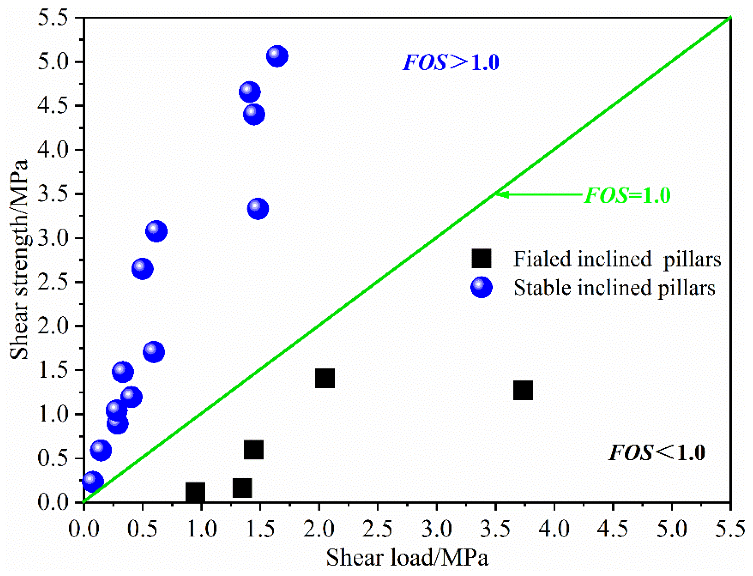
4.2. Verification of Inclined Pillar Shear Strength Model

In total, 18 cases of inclined pillars [32,33] (5 failed pillars and 13 stable pillars) were used to verify the shear strength model of inclined pillars. The relevant parameters of the 18 inclined pillars are shown in Table 1 and Table 2, in which the internal friction angle of the ore-body is 31° and the bulk density of overburden rock mass is calculated according to 27 kN/m3.
To verify the shear strength model of the inclined pillar, the performance of the pillar expressed by the shear strength is expressed by the factor of safety (FOS). The factor of safety is expressed as the ratio of the shear strength to the shear load,
F O S = T p τ θ = 1 sin φ m sin β 1 sin φ m β S p 0 1 k γ H sin θ cos θ 1 η
In Equation (18), when the FOS is greater than 1.0, the pillar is regarded as stable, and when the FOS is less than 1.0, the pillar fails.
The shear strength model of the inclined pillar was derived based on the strength of the vertical pillar and Mohr-Coulomb criterion; thus, it is particularly important to choose the strength model of the vertical pillar. So far, many empirical formulas have been put forward for vertical pillars (including coal pillars and hard rock pillars). Some of the commonly used strength formulas are shown in Table 3.
Among many vertical strength formulas, it is still a challenge to choose a suitable formula to calculate vertical pillar strength. The research shows that the vertical coal pillar strength calculated by Equation (21) is in good agreement with the actual strength in India [7]. Equation (21) was used to calculate the strength of the vertical pillar; according to Equation (15), the shear strength was calculated. Then, Equation (18) was used to calculate the factor of safety of each inclined pillar, and the results are shown in Figure 9. For stable inclined pillars, all the factors of safety are greater than 1.0, while for failed inclined pillars, the factors of safety are much less than 1.0. From the results, it is concluded that the proposed shear strength model is well validated with the field cases, which shows that the proposed shear strength model is reasonable and reliable.
It should be pointed out that the proposed shear model was only verified by some coal pillar cases. Next, this model will be verified using different rock types of inclined pillars or on-site engineering verification. Moreover, the key to using this model to calculate the strength of inclined pillars is to select a suitable formula to calculate the strength of vertical pillars. Therefore, the selection of appropriate formula for the vertical pillar may be a challenge for this research.

5. Analysis of Factors Affecting Bearing Capacity of Inclined Pillar

5.1. Stress Path Effect on the Bearing Capacity of Pillar

The main factors affecting the stress path of the inclined pillar are the area extraction ratio, inclination, and the in-situ stress ratio and their changes in stress state and stress path. If the pillar failure obeys the Mohr-Coulomb strength theory, the relationship between the stress path under the control of three factors and the Mohr-Coulomb strength envelope is presented in Figure 10. Point A represents the average stress state of the vertical pillar controlled by the area extraction ratio, and Point B represents the ultimate stress state at the same position as Point A. Point C represents the average stress state of the inclined pillar controlled by the area extraction ratio, and Point D represents the ultimate stress state at the same position as Point C. Point E represents the average stress state of the vertical pillar controlled by the inclination angle, and Point D represents the ultimate stress state of the inclined pillar at the same position as Point E. Point C represents the average stress state of the vertical pillar controlled by the in-situ stress ratio, and Point F represents the ultimate stress state of the inclined pillar at the same position as Point C. From Figure 10, the straight arrow from Point A to Point B ( A B ) and the straight arrow from Point C to Point D ( C D ) represent the stress path controlled by the area extraction ratio, the arc arrow from Point E to Point D ( E D ) and the arc arrow from Point E to Point F( E F ) represent the stress path controlled by the inclination angle, and the curved arrow from Point C to Point F ( C F ) represent the stress path controlled by the in-situ stress ratio.
The straight arrows A B and C D represent the stress path controlled by the area extraction ratio, where the straight arrow A B represents the stress evolution path on the vertical pillar, and the straight arrow C D represents the stress evolution path on the inclined pillar. With the increase of area extraction ratio, the load on the pillar increases gradually, and the generalized Mohr circle radius increases gradually. The generalized Mohr circle moves outward on a straight line with the slope of tanβ, and the closer the distance to the Mohr-Coulomb strength envelope, the easier it is for the pillar to reach the ultimate stress state. As a result, it demonstrates that the greater the area extraction ratio and the larger the load on the pillar, the greater the risk of pillar instability. Compared with the vertical pillar, it is easier for the stress path of the inclined pillar to reach the ultimate stress state and, hence, the probability of instability is greater.
The arc arrows E D and E F represent the stress path controlled by the inclination angle, where the arc arrow E D represents the stress evolution path when the shear stress component is positive and the arc arrow E F represents the stress evolution path when the shear stress component is negative. The results caused by the two stress paths are the same but in different directions. In this situation, the radius of the generalized Mohr circle is invariant. With the increase of dip angle, the compressive stress component on the pillar decreases, the shear stress component increases, and the distance between the generalized Mohr circle and the strength envelope gradually decreases until it is tangent to the envelope. It can be seen that the change of dip angle is the reason for the transformation between compressive stress and shear stress on the pillar, which shows that in this case, the bearing capacity of the pillar is controlled by the dip angle. The larger the dip angle, the smaller the pillar bearing capacity.
The curve arrow C F represents the stress path controlled by the in-situ stress ratio when the in-situ stress ratio is less than 1 (k < 1.0); with the increase of in-situ stress ratio, the loading condition of the pillar converts to compression from compression-shear loading. The shear stress component on the pillar decreases and the compressive stress increases. Considering that the ore-body material has the characteristics of compressive resistance and not shear resistance, the risk of pillar instability is small, and the ability of pillar resistance to external load is enhanced. When the in-situ stress ratio is more than (k > 1.0), the direction of the shear load changes; with the increase of the in-situ stress ratio, the compressive stress and shear stress on the pillar increase. The generalized Mohr circle center gradually moves below the stress axis σ and gradually approaches the strength envelope; thus, it is easier for the pillar to reach the limit equilibrium state, and the bearing capacity of the pillar is reduced. It should be noted that when the dip angle is small, the higher the in-situ stress ratio, the higher the shear stress concentration on the pillar, which is bound to increase the risk of pillar failure.
To sum up, the changes of area extraction ratio, inclination angle, and in-situ stress ratio change the stress state of the pillar and have a weakening effect on the stability of the pillar. As a result of this weakening effect, the bearing capacity of the pillar decreases, and the pillar gradually evolves from a stable to an unstable state. Specifically, the area extraction ratio changes the total stress, the inclination angle changes the stress property (from compressive stress to shear stress), and the in-situ stress ratio changes the total load of the pillar as well as the property of stress. These changes develop in a direction that is not conducive to the stability of the pillar, resulting in a decrease in the bearing capacity of the pillar. Therefore, the stress evolution path can qualitatively judge the stability of the pillar.

5.2. Stress Path Effect on the Bearing Capacity of Pillar

The effect of the pre-mining stress state and dip angle on pillar stability is reflected in the CFSL. The strength characteristics of the inclined pillar are revealed by analyzing the relationship between the CFSL and pre-mining stress state and inclination angle. In general, the range of dip angle is from 0° to 90°, but there is no fixed formula to calculate the in-situ stress ratio. The most effective method to determine its value is an in-situ stress measurement. In the results of in-situ stress measurements around the world, Brown and Hoek [8] summed up the measured range of the in-situ stress. In-situ stress ratios are bound on the lower side by k = 0.3, while the upper bound is defined by the following expression:
k = 0.3 + 1500 H
where H is the depth below the ground surface in meters. At shallow depth, values of k vary widely and are frequently much greater than unity; at increasing depth, the variability of the ratio decreases, and the upper bound tends towards unity. When H is from 0 to 1000 m, the horizontal stress changes greatly, k∈[0.3, 3.5]; when H is greater than 1000 m, k∈[0.3, 1.0].
Therefore, when the internal friction angle is equal to 31°, the three-dimensional diagram of the equivalent internal friction angle β is drawn when the dip angle θ ∈ [0°, 90°] and the in-situ stress ratio k∈ [0.3, 3.5], as shown in Figure 11. The distribution of three regions of the equivalent friction angle is shown in Figure 11: ① the region greater than 0°, ② the region equal to 0°, and ③ the region less than 0°. When k is from 0.3 to 1.0, β is greater than 0°. When k is equal to 1.0, β is equal to 0°. When k is from 1.0 to 3.5, β is less than 0°. The distribution of β is known, which lays a foundation for analyzing the influence of the in-situ stress ratio and dip angle on the bearing capacity of the inclined pillar.

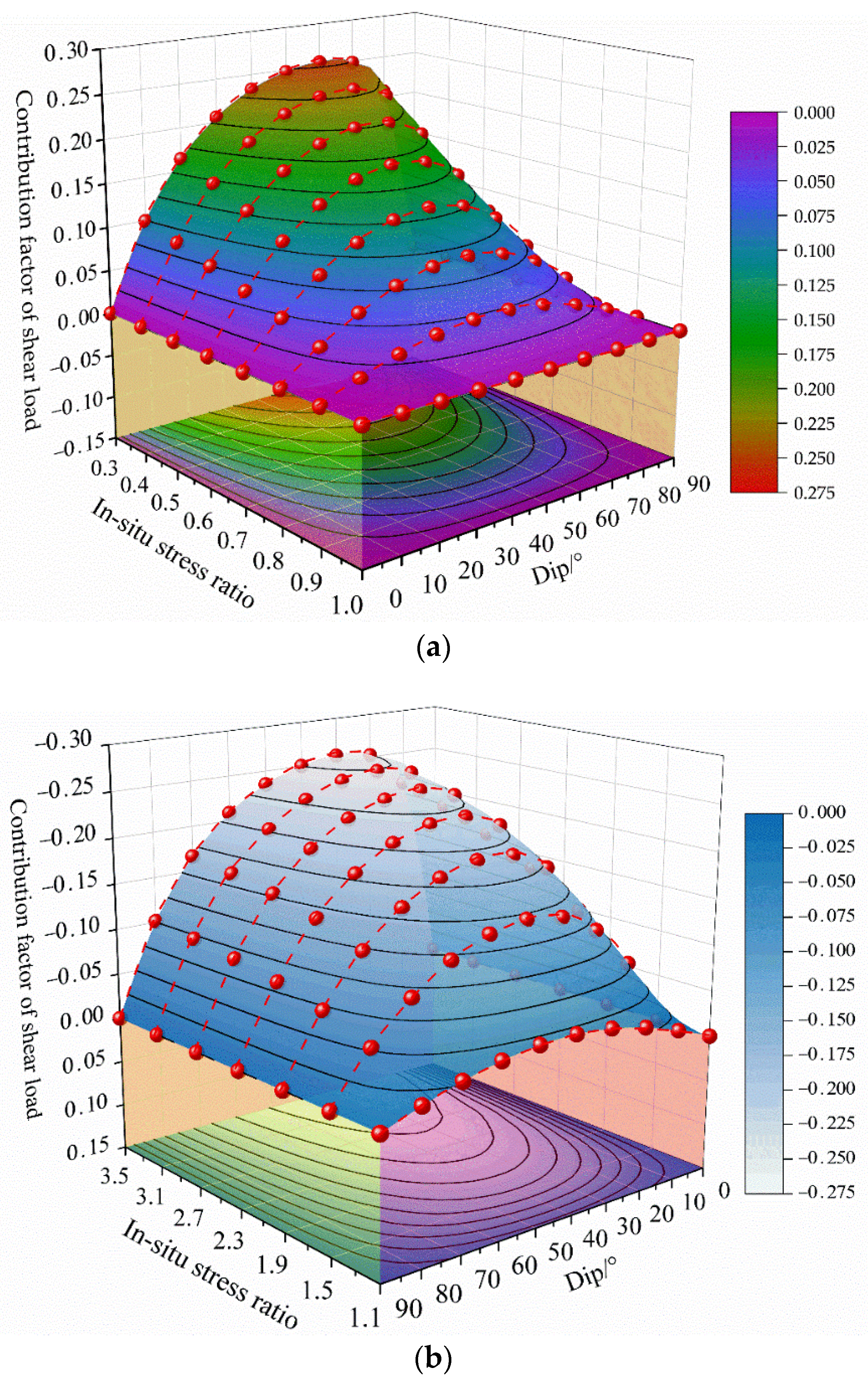
5.3. In-Situ Stress Ratio Effect on the Bearing Capacity of Pillar

When the inclination of the ore-body is constant, the variation law of the contribution factor of shear load (CFSL) is obtained when the k is from 0.3 to 3.5, in which the dip angle θ increases in increments of 10° from 0°, as shown in Figure 12. When the in-situ stress ratio k∈[0.3, 3.5], the CFSL decreases gradually with the increase of the in-situ stress ratio. When k∈[1, 3.5], the CFSL is negative, which shows that the direction of the shear load has changed. When θ = 0° or 90°, the CFSL is equal to 0; the pillar is loaded under pure pressure and is not affected by the external shear load.
Figure 12 demonstrates that, except for 0° and 90°, at any inclination angle, the CFSL decreases with the increase of the in-situ stress ratio. To explore the root cause, the partial derivative of both sides of Equation (16) to the in-situ stress ratio is obtained.
tan β k = 2 sin 2 θ 1 + k + 1 k cos 2 θ 2
From Equation (20), the partial derivative of tanβ to k is always less than zero, indicating that tanβ is a monotone decreasing function. Additionally, the monotonicity of CFSL is affected by the monotonicity of tanβ. When θ∈(0°, 90°), with the increase in the in-situ stress ratio, the CFSL decreases gradually and changes from positive to negative. It shows that the bearing capacity of the pillar increases firstly and then decreases. In addition, the pillar with a small dip angle and a large in-situ stress ratio has a high shear stress concentration, which leads to low bearing capacity.

5.4. Dip Effect on the Bearing Capacity of Pillar

Similarly, when the in-situ stress ratio k is given, the variation of CFSL with dip angle is analyzed. The partial derivatives of θ on both sides of Equation (16) are obtained.
tan β θ = 2 1 k 1 + k cos 2 θ + 1 k 1 + k + 1 k cos 2 θ 2
From Equation (21), when tanβ is a function of θ, its monotonicity is determined by k. When k = 1.0, then tan β θ = 0 , which indicates that tanβ is constant. When k ≠ 1.0, the two cases of k∈[0.3,1.0) and k∈(1.0, 3.5] are analyzed, respectively. Let θ0 be obtained.
θ 0 = 1 2 arccos k 1 k + 1
When k∈[0.3,1.0), the monotonicity of function f is opposite to that of function tanβ. From differential knowledge, let tan β θ 0 ; it shows that the monotone increasing interval of function tanβ is θ∈[θ0, 90°], and the monotone decreasing interval is θ∈[0°, θ0]. Thus, the monotone increasing interval of function f is θ∈[0°, θ0], and the monotone decreasing interval is θ∈[θ0, 90°]. Therefore, when k∈[0.3,1.0), the CFSL first increases and then decreases with the increase of inclination θ, and the CFSL achieves the maximum value at θ = θ0.
In the same way, when k∈(1.0, 3.5], the monotonicity of function f is also opposite to that of function tanβ. Let tan β θ 0 , the monotone increasing interval is θ∈[0°, θ0], and the monotone decreasing interval is θ∈[θ0, 90°]. Therefore, the monotone increasing interval of function f is θ∈[θ0, 90°], and the monotone decreasing interval is θ∈[0°, θ0]. It can be seen that the CFSL decreases at first and then increases with the increase of inclination θ, and the CFSL reaches the minimum value at θ = θ0.
To further illustrate the correctness of the above two conclusions, when k∈[0.3,1.0], the in-situ stress ratio k increases with the increment of 0.1 from 0.3, the variation law of the CFSL with θ is calculated at each value of k, as shown in Figure 13a, which shows that at each value of k, the CFSL decreases at first and then increases with the increase of inclination angle θ. At each value of k, when the CFSL obtains the maximum value, the corresponding angles are 61.29°, 57.69°, 54.74°, 52.24°, 50.08°, 48.19°, and 46.51°, respectively. Similarly, when k∈[1.0, 3.5], the in-situ stress ratio k increases with an increment of 0.4 from 1.1; at this time, the variation of CFSL with θ is shown in Figure 13b, and the CFSL decreases at first and then increases with the increase in inclination θ. At each value of k, when the CFSL obtains the minimum value, the corresponding angles are 43.64°, 39.23°, 35.96°, 33.40°, 31.32°, 29.59°, and 28.13°, respectively.
As shown by Figure 13, the variation of CFSL with inclination angle is consistent with that of theoretical analysis. As a result, it is concluded that when the inclination angle θ is constant (except 0°and 90°), the bearing capacity of the inclined pillar increases and then decreases with the increase of the in-situ stress ratio k, and the bearing capacity is the lowest when θ = θ0. The difference is that when k > 1.0, the dip angle θ corresponding to the minimum pillar bearing capacity is greater than 45°; on the contrary, when k > 1.0, the inclination angle θ is less than 45°.

6. Conclusions

In this research, the influence of shear load on the stress state evolution and bearing capacity of inclined pillars was investigated systematically. Three paths of stress evolution were revealed, and then a shear strength model was proposed to evaluate the bearing capacity of inclined pillars. These conclusions have been summarized as follows.
(1)
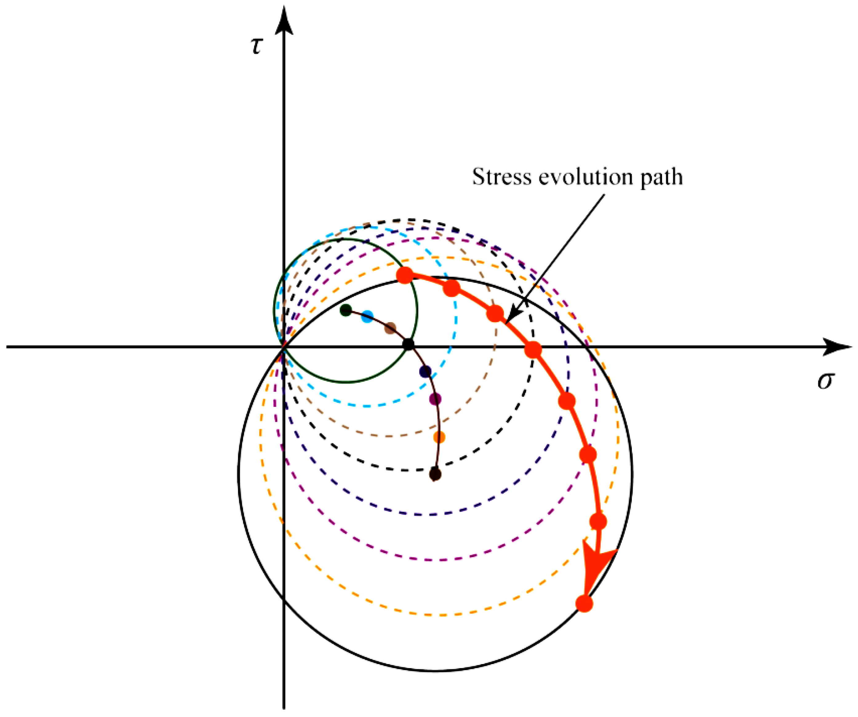
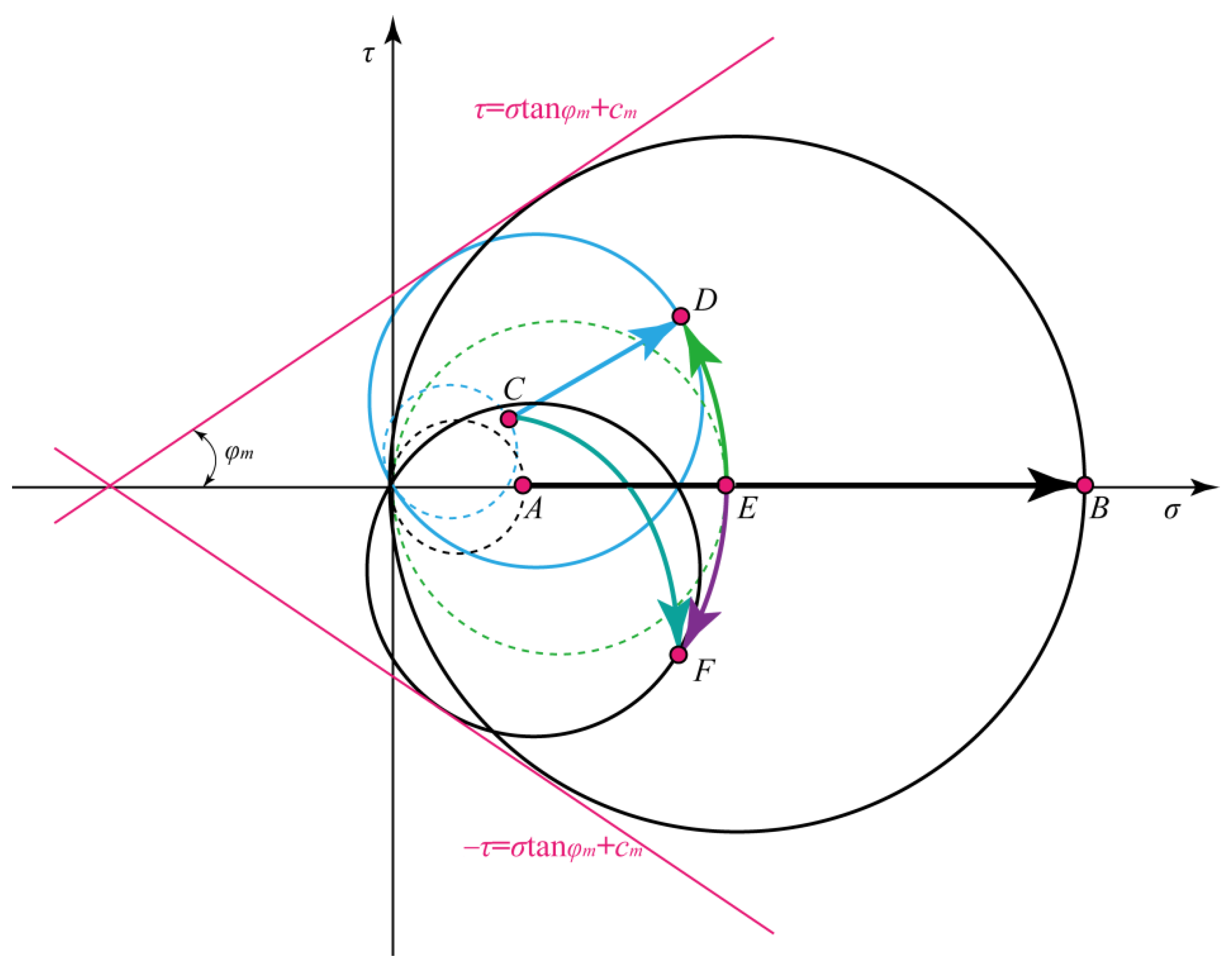
There are three kinds of stress evolution paths of an inclined pillar, which are the stress paths controlled by the area extraction ratio, inclination, and the in-situ stress ratio; the stress paths controlled by the three factors satisfy a straight line, an arc, and a curve, respectively.
(2)
The change of load property of an inclined pillar is the essence of the dip effect on strength. With the increase of inclination angle, the compressive load is transformed into a shear load. As a result, the bearing capacity of the pillar is reduced and the risk of instability is increased.
(3)
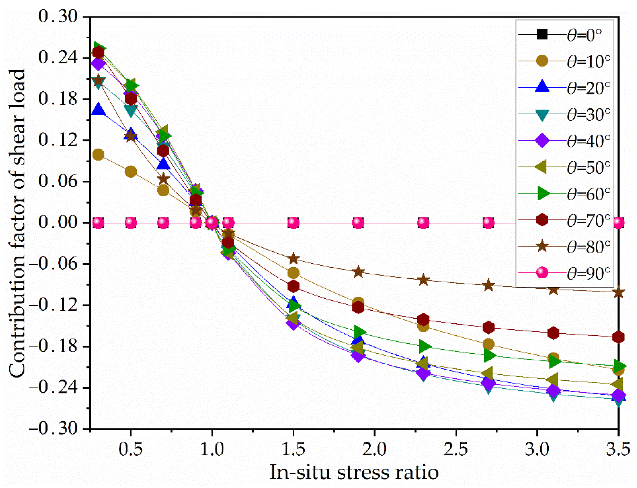
A shear strength model was proposed to evaluate the bearing capacity of inclined pillars. The model is multiplied by a vertical pillar strength model and a dimensionless coefficient that is named the contribution factor of the shear load. The model was used to evaluate the bearing capacity of some inclined failed and stable pillars, and the results are consistent with the actual situation.
(4)
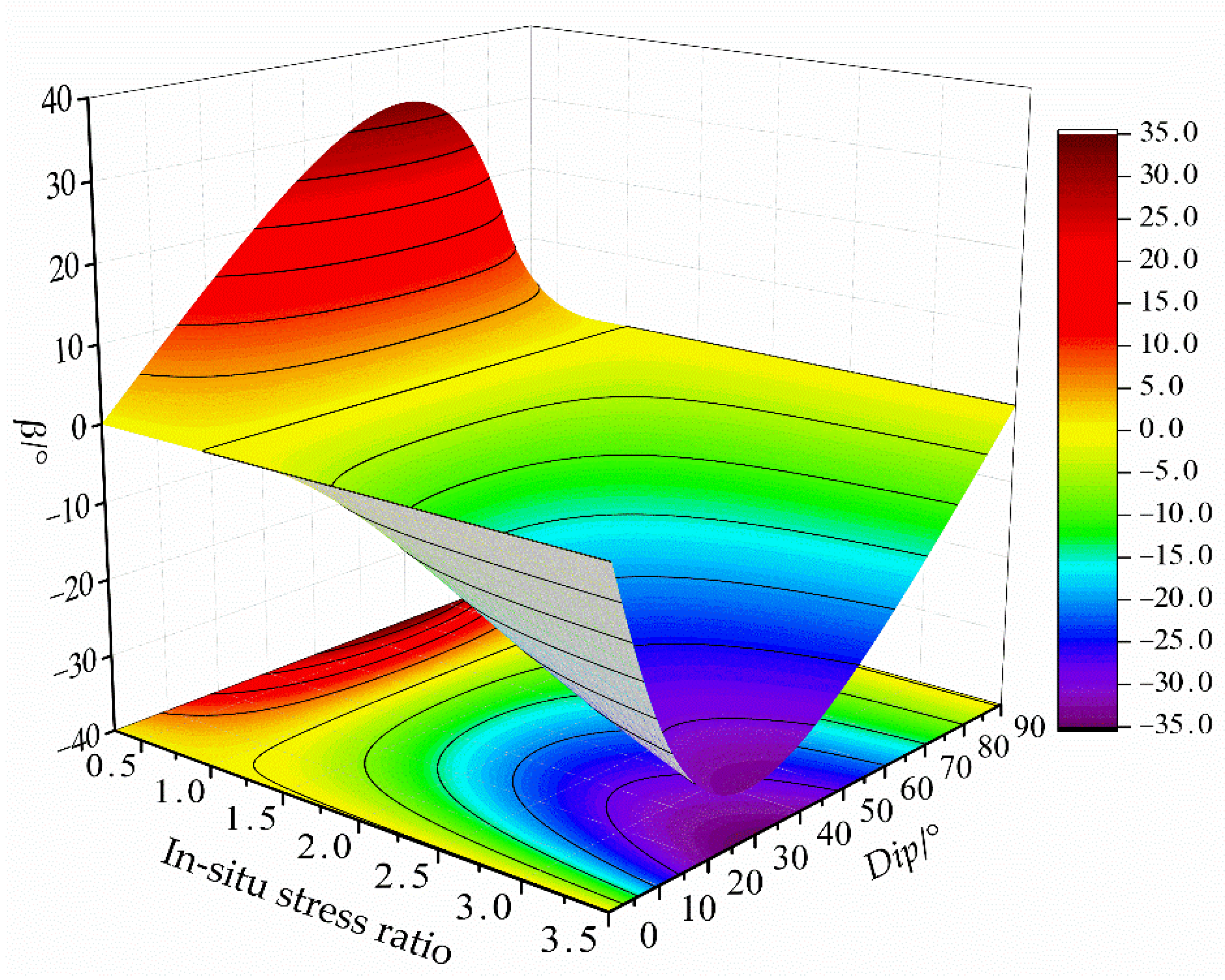
The bearing capacity of an inclined pillar is affected by the in-situ stress ratio and dip angle; when the dip angle θ∈(0°, 90°) and the in-situ stress ratio is less than 1.0, the larger the in-situ stress ratio, the greater the pillar bearing capacity. When the in-situ stress ratio is greater than 1.0, the larger the in-situ stress ratio, the smaller the pillar bearing capacity. In giving an in-situ stress ratio, the bearing capacity of the pillar decreases firstly and then increases with the increase of dip angle.

Author Contributions

Conceptualization, L.S. and Y.Y.; methodology, B.L.; formal analysis, N.H.; writing—original draft preparation, L.S. and B.L.; writing—review and editing, B.L., N.H. and P.L.; funding acquisition, Y.Y. All authors have read and agreed to the published version of the manuscript.

Funding

This research was funded by the Key R&D Projects in Hubei Province (grant number 2020BCA082), the Natural Science Foundation of Hubei Province (grant number 2020CFB123), and the State key R & D Projects (2020YFC1909101).

Institutional Review Board Statement

Not applicable.

Informed Consent Statement

Not applicable.

Data Availability Statement

Data are contained within the article.

Conflicts of Interest

The authors declare no conflict of interest.

References

  1. Ching, J.; Yang, Z.; Shiau, J.; Chen, C. Estimation of rock pressure during an excavation/cut in sedimentary rocks with inclined bedding planes. Struct. Saf. 2013, 41, 11–19. [Google Scholar] [CrossRef]
  2. Liu, S.; Jia, F.; Shen, C.; Weng, L.P. Strength characteristics of soilbags under inclined loads. Geotext. Geomembr. 2018, 46, 1–10. [Google Scholar] [CrossRef]
  3. Zhang, W.; Li, B.; Hwang, H.J.; Weng, L. Punching shear strength of reinforced concrete column footings under eccentric compression: Experiment and analysis. Eng. Struct. 2019, 198, 109509. [Google Scholar] [CrossRef]
  4. Conte, E.; Troncone, A.; Vena, M. Behaviour of flexible piles subjected to inclined loads. Comput. Geotech. 2015, 69, 199–209. [Google Scholar] [CrossRef]
  5. Sohrabi, S.; Banan, M.; Banan, M.R.; Zamiri, A. A new procedure for determination of lateral in-plane failure modes of reinforced concrete squat shear walls. Iran. J. Sci. Technol. Trans. Civ. Eng. 2020, 44, 1047–1056. [Google Scholar] [CrossRef]
  6. Preciado, A.; Sperbeck, S.T. Failure analysis and performance of compact and slender carved stone walls under compression and seismic loading by the FEM approach. Eng. Fail. Anal. 2019, 96, 508–524. [Google Scholar] [CrossRef]
  7. Mohan, G.M.; Sheorey, P.R.; Kushwaha, A. Numerical estimation of pillar strength in coal mines. Int. J. Rock Mech. Min. Sci. 2001, 38, 1185–1192. [Google Scholar] [CrossRef]
  8. Brady, B.H.G.; Brown, E.T. Rock Mechanics for Underground Mining; Springer: Berlin/Heidelberg, Germany, 2006. [Google Scholar]
  9. Peng, S.S. Topical areas of research needs in ground control—A state of the art review on coal mine ground control. Int. J. Min. Sci. Technol. 2015, 25, 1–6. [Google Scholar] [CrossRef]
  10. Yao, Q.; Li, X.; Sun, B.; Ju, M.; Chen, T.; Zhou, J.; Liang, S.; Qu, Q. Numerical investigation of the effects of coal seam dip angle on coal wall stability. Int. J. Rock Mech. Min. Sci. 2017, 100, 298–309. [Google Scholar] [CrossRef]
  11. Pariseau, W.G. Design Analysis in Rock Mechanics, 2nd ed.; CRC Press: Boca Raton, FL, USA, 2011. [Google Scholar]
  12. Luo, B.; Ye, Y.; Li, Y.; Luo, J.; Chen, H. Safety factor method for stability of inclined pillars under Mohr-Coulomb criterion. J. China Coal Soc. 2018, 43, 2408–2415. (in Chinese). [Google Scholar]
  13. Esterhuizen, G.S.; Dolinar, D.R.; Ellenberger, J.L. Pillar strength in underground stone mines in the United States. Int. J. Rock Mech. Min. Sci. 2011, 48, 42–50. [Google Scholar] [CrossRef]
  14. Ma, H.; Wang, J.; Wang, Y. Study on mechanics and domino effect of large-scale goaf cave-in. Saf. Sci. 2012, 50, 689–694. [Google Scholar] [CrossRef]
  15. Li, C.; Xu, J.; Wang, Z.; Qin, S. Domino instability effect of surrounding rock-coal pillars in a room-and-pillar gob. Int. J. Min. Sci. Technol. 2013, 23, 913–918. [Google Scholar] [CrossRef]
  16. Suorineni, F.T.; Kaiser, P.K.; Mgumbwa, J.J.; Thibodeau, D. Mining of orebodies under shear loading Part 1—Case histories. Trans. Inst. Min. Metall. Sect. A Min. Technol. 2011, 120, 137–145. [Google Scholar] [CrossRef]
  17. Kvapil, R.L.; Beaza, J.R.; Flores, G. Block caving at EI Teniente Mine, Chile. Trans. Inst. Min. Metall. Sect. A Min. Technol. 1989, 98, 43–56. [Google Scholar]
  18. Wang, J.; Shang, X.; Ma, H. Investigation of catastrophic ground collapse in Xingtai gypsum mines in China. Int. J. Rock Mech. Min. Sci. 2008, 45, 1480–1499. [Google Scholar] [CrossRef]
  19. Alvarez-Garcia, I.N.; Ramos-Lopez, F.L.; Gonzalez-Nicieza, C.; Alvarez-Fernandez, M.I.; Alvarez-Vigilet, A.E. The mine collapse at Lo Tacón (Murcia, Spain), possible cause of the Torre Pacheco earthquake (2nd May 1998, SE Spain). Eng. Fail. Anal. 2013, 28, 115–133. [Google Scholar] [CrossRef]
  20. Mark, C.; Agioutantis, Z. Analysis of coal pillar stability (ACPS): A new generation of pillar design software. Int. J. Min. Sci. Technol. 2019, 29, 87–91. [Google Scholar] [CrossRef]
  21. Jessu, K.V.; Spearing, A.J.S.; Sharifzadeh, M. Laboratory and numerical investigation on strength performance of inclined pillars. Energies 2018, 11, 3229. [Google Scholar] [CrossRef] [Green Version]
  22. He, Q.; Li, Y.; She, S. Mechanical properties of basalt specimens under combined compression and shear loading at low strain rates. Rock Mech. Rock Eng. 2019, 52, 4101–4112. [Google Scholar] [CrossRef]
  23. He, Q.; Li, Y.; Xu, J.; Zhang, C. Prediction of mechanical properties of igneous rocks under combined compression and shear loading through statistical analysis. Rock Mech. Rock Eng. 2020, 53, 841–859. [Google Scholar] [CrossRef]
  24. Xu, S.; Huang, J.; Wang, P.; Zhang, C.; Zhou, L.; Hu, S. Investigation of rock material under combined compression and shear dynamic loading: An experimental technique. Int. J. Impact Eng. 2015, 86, 206–222. [Google Scholar] [CrossRef]
  25. Luo, B.; Ye, Y.; Hu, N.; Wang, W. Investigation of dip effect on uniaxial compressive strength of inclined rock sample by experimental and theoretical models. Rock Mech. Rock Eng. 2020, 53, 5659–5675. [Google Scholar] [CrossRef]
  26. Jessu, K.V.; Spearing, A.J.S. Effect of dip on pillar strength. J. S. Afr. Inst. Min. Metall. 2018, 118, 765–776. [Google Scholar] [CrossRef]
  27. Lorig, L.J.; Cabrera, A. Pillar strength estimates for foliated and inclined pillars in schistose material. In Proceedings of the 3rd International FLAC/DEM Symposium, Hangzhou, China, 22–24 October 2013; pp. 1–7. [Google Scholar]
  28. Ma, T.; Wang, L.; Suorineni, F.T.; Tang, C. Numerical analysis on failure modes and mechanisms of mine pillars under shear loading. Shock Vib. 2016, 1, 1–14. [Google Scholar] [CrossRef] [Green Version]
  29. Garza-Cruz, T.; Pierce, M.; Board, M. Effect of shear stresses on pillar stability: A back analysis of the troy mine experience to predict pillar performance at montanore mine. Rock Mech. Rock Eng. 2019, 52, 4979–4996. [Google Scholar] [CrossRef]
  30. Suorineni, F.T.; Mgumbwa, J.J.; Kaiser, P.K.; Thibodeau, D. Mining of orebodies under shear loading Part 2—Failure modes and mechanisms. Trans. Inst. Min. Metall. Sect. A Min. Technol. 2014, 123, 240–249. [Google Scholar] [CrossRef] [Green Version]
  31. Das, A.J.; Mandal, P.K.; Bhattacharjee, R.; Tiwari, S.; Kushwaha, A.; Roy, L.B. Evaluation of stability of underground workings for exploitation of an inclined coal seam by the ubiquitous joint model. Int. J. Rock Mech. Min. Sci. 2017, 93, 101–114. [Google Scholar] [CrossRef]
  32. Das, A.J.; Mandal, P.K.; Paul, P.S.; Sinha, R.K.; Tewari, S. Assessment of the strength of inclined coal pillars through numerical modelling based on the ubiquitous joint model. Rock Mech. Rock Eng. 2019, 52, 3691–3717. [Google Scholar] [CrossRef]
  33. Das, A.J.; Mandal, P.K.; Paul, P.S.; Sinha, R.K. Generalised analytical models for the strength of the inclined as well as the flat coal pillars using rock mass failure criterion. Rock Mech. Rock Eng. 2020, 52, 3921–3946. [Google Scholar] [CrossRef]
  34. Zhu, D.; Tu, S. Mechanisms of support failure induced by repeated mining under gobs created by two-seam room mining and prevention measures. Eng. Fail. Anal. 2017, 82, 161–178. [Google Scholar] [CrossRef]
  35. Pariseau, W.G. A symmetry requirement for failure criteria. Int. J. Rock Mech. Min. Sci. 2012, 52, 46–49. [Google Scholar] [CrossRef]
  36. Salamon, M.D.G.; Munro, A.H. A study of the strength of coal pillars. J. S. Afr. Inst. Min. Metall. 1967, 68, 55–67. [Google Scholar]
  37. Prassetyo, S.H.; Irnawan, M.A.; Simangunsong, G.M. New coal pillar strength formulae considering the effect of interface friction. Int. J. Rock Mech. Min. Sci. 2019, 123, 104102. [Google Scholar] [CrossRef]
  38. Sheorey, P.R. Pillar strength considering in-situ stress. In Proceedings of the Workshop on Coal Pillar Mechanics and Design; USBM IC 9315; Iannacchione, A.T., Mark, C., Repsher, R.C., Tuchman, R.J., Jones, C.C., Eds.; United States Department of the Interior: Santa Fe, NM, USA, 1992; pp. 122–127. [Google Scholar]
  39. Hedley, D.G.F.; Grant, F. Stope-and-pillar design for the Elliot Lake Uranium Mines. Bull. Can. Inst. Min. Metall. 1972, 63, 37–44. [Google Scholar]
  40. Potvin, Y.; Hudyma, M.R.; Miller, H.D.S. Design guidelines for open stope support. CIM Bull. 1989, 82, 53–62. [Google Scholar]
Figure 1. Shear failure of a rock pillar [13].
Applsci 11 11439 g001
Figure 2. Sketch of force acting on the inclined layered ore-body and pillar.
Applsci 11 11439 g002
Figure 3. Sketches of inclined pillar stresses. (a) Loading condition of the inclined pillar; (b) stress state of a single pillar; (c) stress state of the arbitrary inclined plane.
Applsci 11 11439 g003
Figure 4. Generalized Mohr’s circle characterization of the stress state of an inclined pillar.
Applsci 11 11439 g004
Figure 5. Stress path controlled by the area extraction ratio.
Applsci 11 11439 g005
Figure 6. Stress path controlled by dip angle.
Applsci 11 11439 g006
Figure 7. Stress path controlled by the in-situ stress ratio.
Applsci 11 11439 g007
Figure 8. The relationship between the generalized Mohr circle and the strength envelope.
Applsci 11 11439 g008
Figure 9. Shear load vs. shear strength of failed and stable inclined pillar cases.
Applsci 11 11439 g009
Figure 10. Stress evolution path of inclined pillars.
Applsci 11 11439 g010
Figure 11. The β vs. in-situ stress ratio and dip angle (φm =31°).
Applsci 11 11439 g011
Figure 12. Relationship between the contribution factor of shear load (CFSL) and the in-situ stress ratio.
Applsci 11 11439 g012
Figure 13. Relationship between the contribution factor of shear load (CFSL) and dip angle; (a) k∈[0.3, 1]; (b) k∈(1, 3.5].
Applsci 11 11439 g013
Table 1. Failed inclined pillar cases [32,33].
Pillar Case NumberDepth/mPillar Height/mPillar Width/mDip/DegreeIn-Situ Stress Ratio (k)Roadway Width/mUCS of Intact Ore-Body/MPa
1952.03.0 × 7.1522.02.104.227.6
21031.82.0 × 7.1518.31.334.28.3
3731.82.0 × 7.1518.31.714.244.7
4651.82.0 × 9.2014.01.903.618.3
52351.52.5 × 13.1512.40.814.58.1
Table 2. Stable inclined pillar cases [32,33].
Pillar Case NumberDepth/mPillar Height/mPillar Width/mDip/DegreeIn-Situ Stress Ratio (k)Roadway Width/mUCS of Intact Ore-Body/MPa
1952.018.3 × 18.322.02.104.227.60
21031.820.8 × 18.318.31.334.28.30
3731.820.8 × 18.318.31.714.244.70
4651.822.4 × 22.414.01.903.618.30
51293.025.0 × 35.014.01.144.516.45
63803.453.6 × 53.612.41.115.518.90
73803.462.8 × 62.812.41.115.518.90
84573.053.8 × 53.815.60.614.214.92
9445.32.853.8 × 53.815.60.614.215.34
102351.530.5 × 30.512.40.814.58.10
112402.530.0 × 30.022.00.804.528.00
124002.543.5 × 43.522.00.644.528.00
133153.040.8 × 40.810.90.964.217.79
Table 3. Strength formulas of partial vertical pillars (coal pillars and hard rock pillars).
No.AuthorFormulaSlRemarksEq.
1Salamon et al. [36] S p 0 = S l w 0.46 h 0.66 7.2Coal pillar(19)
2Prassetyo et al. [37] S p 0 = S l 0.12 + 0.88 w h 2.7Coal pillar(20)
3Sheorey et al. [7,38] S p 0 = S l h 0.36 + H 250 + 1 w h 1 0.27σ0Coal pillar(21)
4Hedley et al. [39] S p 0 = S l w 0.5 h 0.75 132.9Hard rock pillar(22)
5Potvin et al. [40] S p 0 = S l w h 0.42σ0Hard rock pillar(23)
6Esterhuizen et al. [13] S p 0 = S l L D F w 0.30 h 0.59 LDF∈(0, 1)0.65σ0Hard rock pillar(24)
Publisher’s Note: MDPI stays neutral with regard to jurisdictional claims in published maps and institutional affiliations.

