Article

Recording a Hologram Transmitted over a Communication Channel on One Sideband

by
Sergey A. Shoydin
1,2,*,
Sergey B. Odinokov
3,†,
Artem L. Pazoev
1,
Ivan K. Tsyganov
3 and
Ekaterina A. Drozdova
3
1
Department of Photonics and Device Engineering, Siberian State University of Geosystems and Technologies, 10 Plakhotnogo St., 630108 Novosibirsk, Russia
2
Laboratory of Dispersed Systems, Voevodsky Institute of Chemical Kinetics and Combustion of Siberian Branch of the RAS, 3 Institutskaya St., 630090 Novosibirsk, Russia
3
Laser and Optoelectronic Systems Department, Bauman Moscow State Technical University, 5/1 2nd Baumanskaya St., 105005 Moscow, Russia
*
Author to whom correspondence should be addressed.
Dedicated to the memory of author Sergey B. Odinokov, who passed away during the preparation of this manuscript.
Appl. Sci. 2021, 11(23), 11468; https://doi.org/10.3390/app112311468
Submission received: 11 November 2021 / Revised: 24 November 2021 / Accepted: 26 November 2021 / Published: 3 December 2021
(This article belongs to the Special Issue Holographic Technologies: Theory and Practice)

Abstract

:
The paper presents experimental results on the recording and restoration of 3D holographic frames suitable for transmitting 3D holographic images with the frame rate required for TV images and a resolution of the Full HD standard and higher. The Patent RF No. 2707582 proposed a method for compressing holographic information and transmitting it using a procedure similar to SSB over conventional communication channels. In this work, the holographic information of a 3D portrait of a person, transmitted and received via the Wi-Fi communication channel, was restored in the form of a rainbow hologram, as one of a variety of holograms, by the computer addition of the carrier spatial frequency, and then hologram was actually produced on a photoresist. This technology can be used to create a holographic phototelegraph or, if there is a dynamic holographic display, to create a holographic television and 3D augmented reality.

1. Introduction

The problems related to holographic TV infringe on the interests of experts both in the area of holography and in image coding. For this reason, the Joint Photographic Experts Group (JPEG) has announced a competition of the proposals in holographic coding [1,2,3]. In its standard ISO/IEC 21794 [4], JPEG proposed solutions for coding more complete light field data [5] through creating a 4D array of the data on the light wave, with subsequent purely mathematical elimination of redundancy, similar to Huffman codes, for an increase in the entropy of an encoded message. High requirements in terms of the amount of information processed in this manner and the processing rate are also mentioned. This is due to the fact that each frame, which is a 3D array of the object holographing data, should change at a frame rate accepted by the major TV standards. This approach is implemented at present within the technologies of point cloud [6,7], polygonal [8,9] and voxel [10,11] representation of 3D images. Transmission of the real-time 3D images requires not only high computer productivity, but also the immense throughput capacity of the communication channel. Indeed, the density of holographic data records is limited by diffraction effects and is proportional to the spatial frequencies in a frame, inversely proportional to the size of the Airy spot [12,13,14]. In other words, the number of points on a hologram is inversely proportional to the size of the Airy spot, and for the focused image holograms, their number is inversely proportional by the order of magnitude to the wavelength. Within the visible range, for a hologram of a portrait image of A4 size (210 mm × 297 mm), which corresponds to a television screen of 14 inches diagonal, at λ = 0.63 µm, the number of points on the hologram reaches n = 1.6 × 10¹¹. For the binary record, this corresponds to the same amount of information measured in data bits. This is approximately n = 2 × 1010 bytes ≈ 20 GB, which is equivalent to the information contained in an hour-long film of the Full HD standard. For transmission along a radio channel with a frame rate of 25 frames/s, this will take a bandwidth of about 500 GHz and will overlap the whole radio range available for mankind, pushing out all other radio and television channels. A way out of the formed contradiction is either a substantial decrease in the size of the holographic image, which does not correspond to the requirements of augmented reality, or the compression of the holographic information so that its amount would not exceed reasonable limits—that is, the possibilities of the modern communication channels 3G and 4G.
To solve this problem, we chose another method of transmitting the holographic information, as presented in [14,15] and covered by RF Patent [16]. The essence of this method is in recognizing that it is not necessary to transmit the whole amount of holographic information for the creation of a 3D holographic image at the receiver end of the communication channel; it is sufficient to only transmit the part responsible for carrier modulation. In spite of the fact that the modulation in holography is more complicated, this is very similar to the SSB method, because the spatial frequencies of the carrier are already input at the receiving end of the communication channel. The difference between the proposed method and the SSB is the fact that the side spatial frequencies are not transmitted, but are still created at the receiving end of the communication channel on the basis of the two transmitted image modes: depth map + surface texture of the 3D holographic object. So, a 4D file of the holographic content considered in [4,5], which is a time-base sweep of 3D images, is replaced by the time-base sweep of two 2D images, to which JPEG compression has already been applied. The first of these two images is the surface texture of the 3D object, similar to a common photographic image or a series in a video. The second is a map of the 3D surface onto which the texture is superimposed, thus forming an image of the 3D object, or a mask of the object. Thus, extremely large amounts of information contained in holograms and preventing transmission along conventional communication channels may be compressed without any damage to the acceptable size, comparable with a generally accepted television frame of the Full HD or 4K standard. In this case, transmission of holographic information (Figure 1) resembles the single sideband modulation (SSB) known in radio engineering, because the carrier spatial frequency responsible for the spatial separation of the zero and minus first diffraction order carrying the information on the 3D holographic object is absent in this case.
The holograms of the single sideband of spatial frequencies, transmitted along the channel, were synthesized by returning the carrying spatial frequency. It is rather difficult to reproduce these holograms using the classical method of repeating holographing technology according to the scheme proposed by E. N. Leith and J. Upatnieks. This can be implemented in a much easier manner using the technology based on S. Benton’s recording scheme. The first hologram transmitted along a conventional communication channel in real time was recorded using this technology. The parallax of the image restored by this hologram was measured. The outlooks for the use of these holograms are discussed.
The direct SSB transmission was performed along the Wi-Fi channel in the packages containing 500 pairs of images, as in those shown in Figure 1a,b, with the measurement of transmission rate [17].
An experimental transmission of the sequence of signal pairs of this kind (Figure 1a,b) was carried out over a wireless Wi-Fi channel to imitate a 3D video. For this purpose, a File Transfer Protocol (FTP) was installed at the transmitting device, while the FileZilla software for working with FTP servers was installed at the receiving device. Each transmitted frame of a 3D image was the sum of two 2D frames: a texture (2000 × 2000 pixels) and a mask (1000 × 1000 pixels). To imitate the transmission of a video sequence, the packages of 500 double frames was transmitted simultaneously. The time of the frame package transmission measured using FileZilla software during reproduction in real time was 12 s for the frames formed in the JPEG file format, and 51 s for the frames formed in the PNG format, which is equivalent to transmitting 41.67 and 9.8 double frames per second, respectively. This means that, at least for the JPEG format, the actual rate of 3D signal transmission within a narrow bandwidth of the Wi-Fi channel (IEEE 802.11n standard) was sufficient to provide the TV frame rate standard. On this basis, it may be concluded that the transmission of a full image of a 3D object in real time, with a frame rate higher than 25 frames per second, is quite accomplishable with this device configuration.
The hologram is synthesized at the receiving end of communication channel with the help of the digital method using the transmitted information on the 3D holographic object. This hologram is a material analog of a holographic display [14] reconstructing the image of this object. This hologram may be of any type; however, virtual synthesis of the most widespread holographic displays, according to the scheme proposed by Yu. N. Denisyuk [18], is hindered during the transformation of a virtual hologram into its material analog. Because of this, in our first paper presented at the HoloExpo 2021 conference Features of the synthesis of SSB holograms (SSBH) [19], we chose the synthesis of holograms at the receiving end of the communication channel, according to the scheme proposed by E. N. Leith and J. Upatnieks. However, the work with this type of hologram involves several problems that are difficult to solve. These problems are first of all connected with the necessity to make fast Fresnel transforms describing the propagation of the complex amplitude of the electromagnetic field in the space from the object to the hologram, and from the hologram to the observation plane within the scalar approximation of diffraction theory [20], as well as with the practical difficulties in the realization of point-by-point recording of large data arrays. In addition, this type of hologram is not reconstructed with white light—firstly, because the spectral blooming Δy of the points in the image, which is proportional to spectrum width Δλ and the distance Z from the hologram plane to the point of holographed image, is characterized by substantial extension at a large distance from the hologram, as shown by Equation (1), where θR is the angle of reference beam inclination:
Δyλ ≈ (Δλ/λ)∙Z∙θR,
Secondly, the angular size θ of white light sources is much larger than that of a laser source, which also leads to blurring. See Equation (2):
Δyθ ≈ θ∙Z.
For a white light source (Δλ = λ), with the angular size of the luminous body θ = 1/200, placed at a distance of best viewing distance (Z = 250 mm), these values will be Δyλ = 250 mm and Δyθ = 1.2 mm, respectively.
One can see in Equations (1) and (2) that the values of both types of blurring are proportional to the distance from the image to the hologram, so it is convenient to consider so-called focused image holograms [21], because blurring is minimal in this case. A dynamic monitor operating in the real time mode can recover the image by laser radiation, and then three lasers will be necessary for a full-color image (RGB color coding); otherwise, white color may be used (Yu. N. Denisyuk’s thick hologram and S. Benton’s thin rainbow holograms). We chose the holograms recovered with white light, and among them, S. Benton’s holograms [22], because it is very difficult to synthesize Denisyuk’s material holograms from their digital models. In addition, in rainbow holograms, the entropy decreases due to the elimination of the vertical parallax, which causes a decrease in the amount of information in the hologram; information overload not only hinders the transmission along communication channels [23], but also brings complications into computer synthesis. Moreover, the horizontal parallax is in much higher demand than the vertical one, so at the first stage we chose Benton’s rainbow hologram for experimental recording.

2. Experimental Recording of a Rainbow Hologram at the Receiving End of the Communication Channel

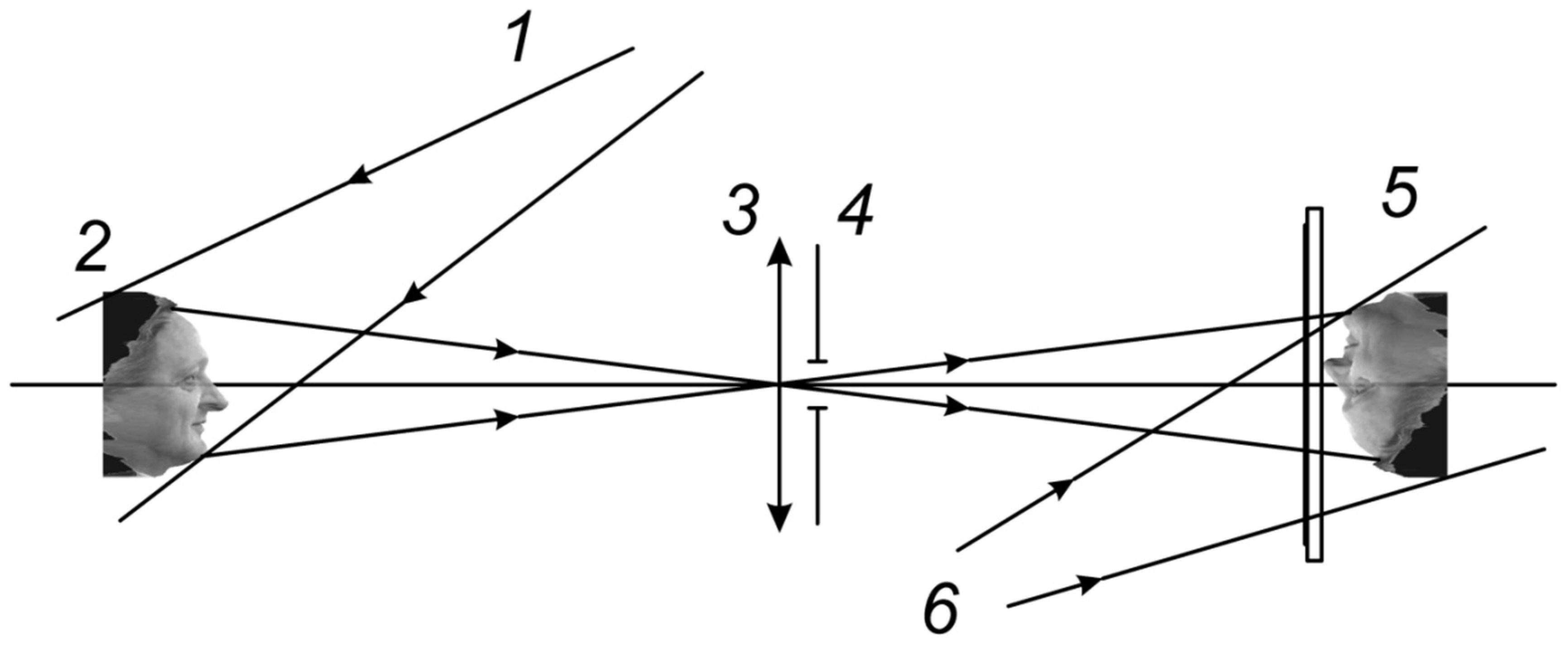
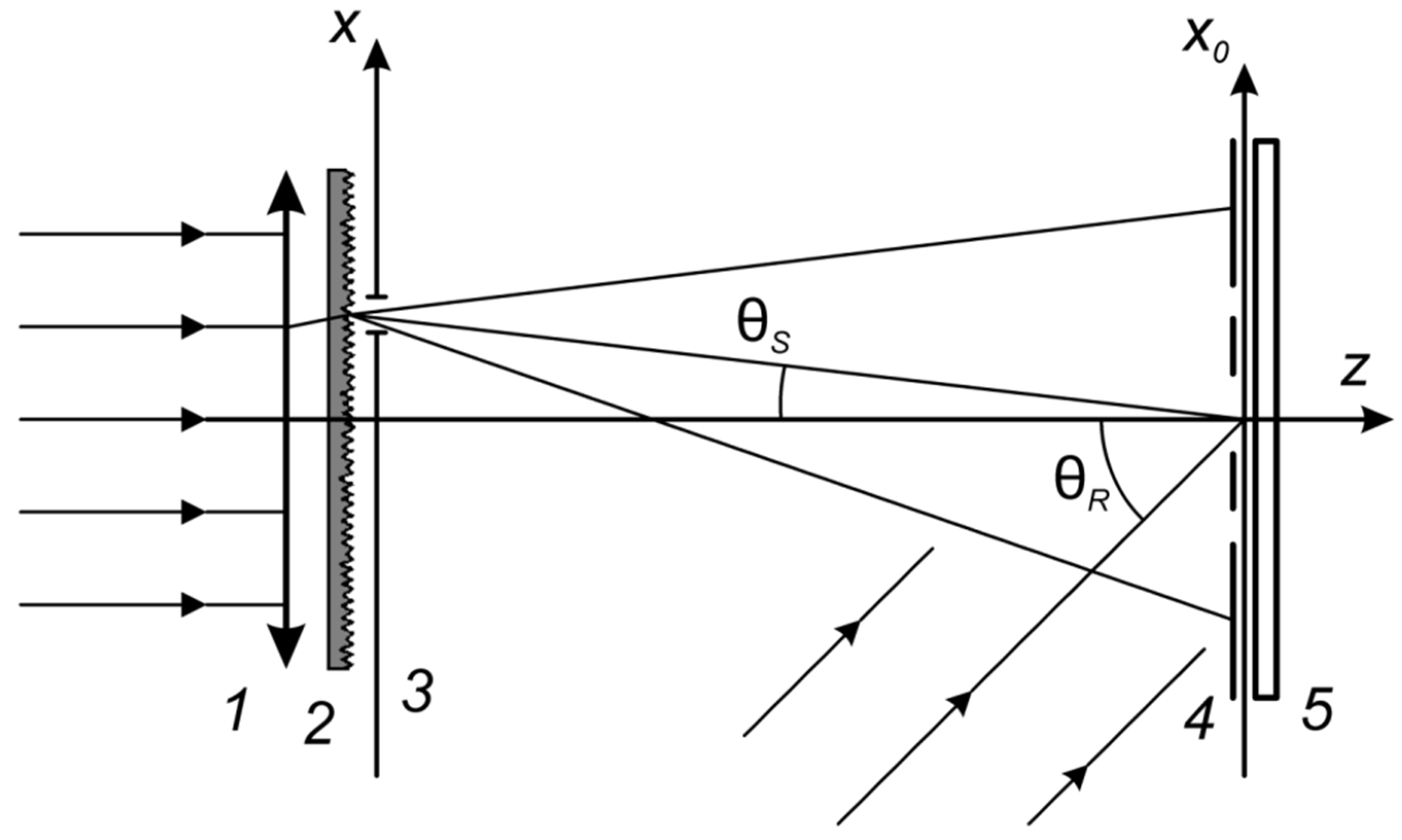
A single-step scheme of recording a rainbow hologram is presented in Figure 2, while its version for recording flat colored images is shown in Figure 3. If several flat images are recorded according to the latter scheme, rotating the photographic plate around the vertical axis between exposures, each image will be reconstructed at its own angle during reconstruction, thus providing the parallax effect.
The image of holographed object 2, backlit by beam 1, which is coherent with 6, is transmitted to the photographic plate 5 through the filter 4 of vertical spatial frequencies so that, according to [24], S. Benton’s rainbow hologram is formed. Its speckle structure is extended along the vertical axis and has a complete set of horizontal spatial frequencies (Figure 4).
This hologram contains less information on the object because the vertical parallax is absent from it, and in the white light, it recovers a monochrome image, which is iridescent to the onlooker’s eyes moving vertically. Its appearance suggests that this hologram may be synthesized with the help of a set of columns composed of short, differently directed segments.
A colored image of the object may be obtained, for example, according to the scheme shown in Figure 3, where a slit source 3 with a random phase mask 2 forms an object wave on hologram 5, with the spatial modulation by mask 4. The latter is chosen from different spectral regions of the flat image to be recorded in accordance with Bragg angle θs, so that the reconstruction angle would be identical for any of the recorded waves [25].
Not only one, but several flat images taken at different angles may be recorded on a holographic plate (Figure 5).
These holograms, when irradiated with a beam analogous to the reference one, but with a wide spectral range, will reconstruct the images perceptible as those having a horizontal parallax; they may be considered one of the possible versions of colored 3D displays.
It is known that the development of a number of complicated optical–mechanical schemes implementing these colored displays on the basis of S. Benton’s rainbow holograms have been carried out over some time [26]. However, as a rule, a record of this kind would possess low angle selectivity for thin holograms and low diffraction efficiency because of the rapid exhaustion of the dynamic range of photoresponse. These disadvantages may be eliminated using the DotMatrix technology, in which a photographic plate is divided into a series of so-called holopixels, so that each of them is, in turn, composed of a set of j regions corresponding to the number of recorded incidence angles. A flat image of the 3D image at only one incidence angle is recorded on each j region in all holopixels. Irradiation of the obtained rainbow focused image holograms produces a stereo effect, providing a horizontal parallax of a series of approach angles of the colored images of the initial 3D object.
For the experimental recording of an SSB hologram in the rainbow hologram technology, we chose a KineMax MASTERING SYSTEM (Polish Holographic Systems, Warsaw, Poland) (Figure 6), in which a complicated set of optical elements was maximally replaced by the computer synthesis of the corresponding diffraction gratings.
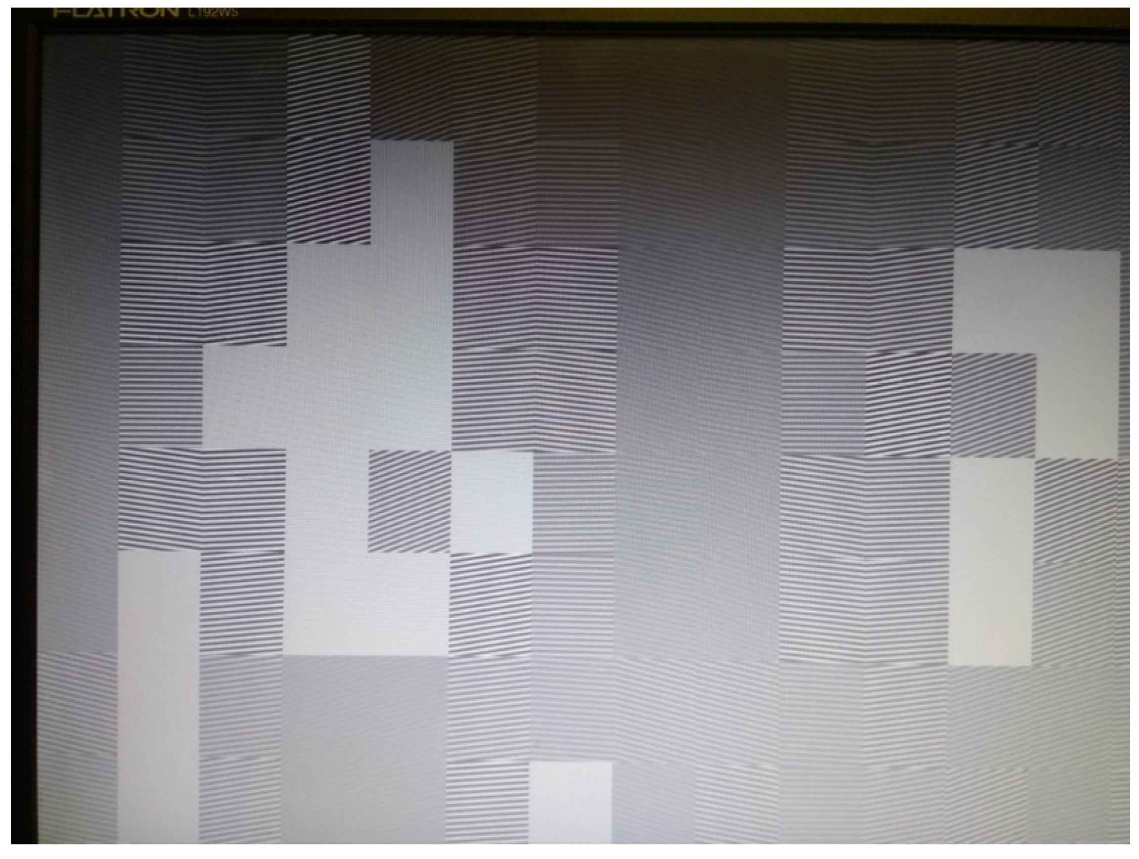
Under objective 14, there is an area-mobile objective table onto which the photoresist is placed. The image of several gratings formed by the LC-SLM (Figure 7) is projected through objective 9 onto the corresponding region of the photoresist.
The hologram, as a whole, is recorded by moving the table and projecting a specific calculated set of spatially oriented gratings onto every region; the hologram is composed of a set of holopixels, each containing a region for each of the j images to be recorded (Figure 8).
One can see that the structures obtained through the calculation and composition of the vertical segments with the bands oriented transversely at different angles (Figure 8) are very similar to those obtained in the classical S. Benton’s scheme (Figure 4).

3. Results and Discussion

A general view of the hologram recorded with the KineMax device is shown in Figure 9.
The parallax observed in the image reconstructed from this hologram is presented in Figure 10.
One can see in Figure 10 that the reconstructed images actually exhibit the parallax effect. The value of the parallax may be measured directly with the help of porting out the hologram-reconstructed image using a telescopic system (Figure 11).
The parallax is observed in the space into which the hologram-reconstructed image is ported (See Video S1). The test structures were two needles placed apart from each other at a distance equal to the object depth along the optical axis of the stand of the image reconstruction by the hologram. The upper needle is closer to the hologram along the optical axis, and the lower one is at a longer distance. The positions of the needles were chosen so that their tips remained almost non-shifted from the selected reference point on the object with a change in the angle of rotation of the reconstructed image. The distance between the needles was measured and was found to be equal to 5.85 mm; the telescopic system had a 9-fold longitudinal magnification, which corresponds to the depth of the hologram-reconstructed image equal to 0.65 mm.

4. Conclusions

Other representations of the 3D holographic signal that are widely developed today, such as the point cloud technology mentioned above [6,7], polygonal [8,9] and voxel [10,11] representations of three-dimensional images, have extensive bibliography, which cannot be reflected in our article. We can only address review papers, for example [27,28]. In Table 1, we presented some of, we believe, the key stages of our development based on the creation of a mask using structured light, and the parallel development of our foreign colleagues based on the creation of a mask (surface map) using a time-of-flight (ToF) camera. We believe that the low resolution in the depth of the recorded scene is inherent in the ToF technology, since the operation of the electronics serving it must exceed 300 GHz per pixel for the high-quality registration of a 3D image of a human portrait. At the same time, the technology we are developing for using structured light does not have such strict limitations, and is much better adapted for transmitting 3D holographic images over distance. This also applies to portrait images in the TV standard of spatial resolution, with continuous parallax of the image depth, as well as with the TV frame rate.
In the present paper, the data from the holographic 3D object were actually transmitted by us through a Wi-Fi channel in the form of two frames (a mask and a texture, as shown in Figure 1), so it may be concluded that the cycle involving the recording of a 3D image of the object; its transmission through a conventional radio channel with the accepted TV frame rate; the synthesis of a rainbow focused image hologram, which is equivalent to recording flat holograms at 15 incidence angles; the reconstruction of a 3D image of the object; and the observation of the parallax in the image were all carried out successfully. This allows us to conclude that it is possible to transmit holograms in real time through conventional communication channels using a method similar to SSB. Thus, the possibility of implementing a holographic phototelegraph was confirmed experimentally. The authors hope that the data described in this paper will be useful for the developers of dynamic holographic 3D displays to solve the problems of visual reality and holographic TV.

Supplementary Materials

The following are available online at https://www.mdpi.com/article/10.3390/app112311468/s1: Supplementary Video S1: Parallax of a 3D image reconstructed from a material hologram.

Author Contributions

Conceptualization, S.A.S.; methodology, S.A.S. and S.B.O.; software, A.L.P., I.K.T. and E.A.D.; validation, S.A.S., A.L.P., S.B.O., I.K.T. and E.A.D.; formal analysis, S.A.S., A.L.P. and I.K.T.; investigation, A.L.P. and E.A.D.; resources, S.B.O.; data curation, S.A.S. and S.B.O.; writing—original draft preparation, S.A.S.; writing—review and editing, A.L.P.; visualization, A.L.P.; supervision, S.A.S.; project administration, S.A.S.; funding acquisition, S.A.S. and S.B.O. All authors have read and agreed to the published version of the manuscript.

Funding

This research received no external funding.

Institutional Review Board Statement

Ethical review and approval were waived for this study, due to the fact that the texture, mask and 3D images used in the study are the personal images of the first author of this article, Sergey Alexandrovich Shoydin. Sergey Alexandrovich Shoydin hereby declares that his images can be used in this article. The authors of other scientific articles can also use the 3D images, mask and texture with the image of Sergey Alexandrovich Shoydin used in this work in their scientific articles with the obligatory reference to this work.

Informed Consent Statement

Informed consent was obtained from all subjects involved in the study.

Data Availability Statement

Data are available from the authors upon request.

Acknowledgments

The authors thank all reviewers for their helpful comments and suggestions.

Conflicts of Interest

The authors declare no conflict of interest.

References

  1. Ebrahimi, T.; Foessel, S.; Pereira, F.; Schelkens, P. JPEG Pleno: Toward an Efficient Representation of Visual Reality. IEEE MultiMedia 2016, 23, 14–20. [Google Scholar] [CrossRef]
  2. Schelkens, P.; Ebrahimi, T.; Gilles, A.; Gioia, P.; Oh, K.-J.; Pereira, F.; Perra, C.; Pinheiro, A.M.G. JPEG Pleno: Providing representation interoperability for holographic applications and devices. ETRI J. 2019, 41, 93–108. [Google Scholar] [CrossRef] [Green Version]
  3. Muhamad, R.K.; Birnbaum, T.; Gilles, A.; Mahmoudpour, S.; Oh, K.-J.; Pereira, M.; Perra, C.; Pinheiro, A.; Schelkens, P. JPEG Pleno holography: Scope and technology validation procedures. Appl. Opt. 2021, 60, 641–651. [Google Scholar] [CrossRef] [PubMed]
  4. ISO/IEC 21794. In Information Technology—Plenoptic Image Coding System (JPEG Pleno); ISO/IEC: Geneva, Switzerland, 2020.
  5. Schelkens, P.; Astola, P.; da Silva, E.A.B.; Pagliari, C.; Perra, C.; Tabus, I.; Watanabe, O. JPEG Pleno light field coding technologies. In Applications of Digital Image Processing XLII; SPIE Optical Engineering + Applications: San Diego, CA, USA, 2019; Volume 11137, p. 111371G. [Google Scholar] [CrossRef]
  6. Thanou, D.; Chou, P.A.; Frossard, P. Graph-Based Compression of Dynamic 3D Point Cloud Sequences. IEEE Trans. Image Process. 2016, 25, 1765–1778. [Google Scholar] [CrossRef] [PubMed] [Green Version]
  7. Liu, M.; Zhao, J.; Guo, X.; Zhuang, R. Application of Improved Point Cloud Streamlining Algorithm in Point Cloud Registration. In Proceedings of the 2020 Chinese Control and Decision Conference (CCDC), IEEE, Hefei, China, 22–24 August 2020; pp. 4824–4828. [Google Scholar] [CrossRef]
  8. Botsch, M.; Pauly, M.; Kobbelt, L.; Alliez, P.; Lévy, B.; Bischoff, S.; Rössl, C. Geometric modeling based on polygonal meshes. In ACM SIGGRAPH 2007 Courses; Association for Computing Machinery: San Diego, CA, USA, 2007. [Google Scholar] [CrossRef] [Green Version]
  9. Nasri, A.H. Constructing polygonal complexes with shape handles for curve interpolation by subdivision surfaces. Comput.-Aided Des. 2001, 33, 753–765. [Google Scholar] [CrossRef]
  10. Lee, S.; Hong, H.; Eem, C. Voxel-Based Scene Representation for Camera Pose Estimation of a Single RGB Image. Appl. Sci. 2020, 10, 8866. [Google Scholar] [CrossRef]
  11. Huang, M.; Wei, P.; Liu, X. An Efficient Encoding Voxel-Based Segmentation (EVBS) Algorithm Based on Fast Adjacent Voxel Search for Point Cloud Plane Segmentation. Remote Sens. 2019, 11, 2727. [Google Scholar] [CrossRef] [Green Version]
  12. Titar, V.P.; Bogdanova, T.V. Issues in creating holographic television system. Radioelectron. Inf. 1999, 2, 38–42. [Google Scholar]
  13. Denisyuk, Y.N. Are the fundamental principles of holography well-known enough for creating new types of three-dimensional films and artificial intelligence? Tech. Phys. 1991, 61, 149–161. [Google Scholar]
  14. Shoydin, S.A. Synthesis of holograms received by a communication channel. Comput. Opt. 2020, 44, 547–551. [Google Scholar] [CrossRef]
  15. Shoydin, S.A.; Pazoev, A.L. Method of holographic recording remote formation. Avtometriya 2021, 1, 92–102. [Google Scholar] [CrossRef]
  16. Shoydin, S.A. Method of Holographic Recording Remote Formation. Patent RF No. 2707582, 28 November 2019. [Google Scholar]
  17. Pazoev, A.L.; Shoydin, S.A. Transmission of holographic information on a single sideband. In Collection of Materials of the National Conference with International Participation “SibOptika-2021”. Section 2: Optical and Optoelectronic Instrumentation; SSUGT: Novosibirsk, Russia, 2021; Volume 8, pp. 109–117. [Google Scholar] [CrossRef]
  18. Denisyuk, Y.N. On reflecting optical properties of an object in the wave field of radiation scattered by this object. Proc. USSR Acad. Sci. 1962, 144, 1275–1278. [Google Scholar]
  19. Shoydin, S.A.; Pazoev, A.L. Features of the synthesis of SSB holograms (SSBH). In Proceedings of the HOLOEXPO 2021: XVIII International Conference on Holography and Applied Optical Technology, Moscow, Russia, 21–22 September 2021. [Google Scholar]
  20. Goodman, J.W. Introduction to Fourier Optics; Mir Publishers: Moscow, Russia, 1970; 364p. [Google Scholar]
  21. Stroke, G.W. White-light reconstruction of holographic images using transmission holograms recorded with conventionally-focused images and “in-line” background. Phys. Lett. 1966, 23, 325–327. [Google Scholar] [CrossRef] [Green Version]
  22. Benton, S.A. Hologram reconstruction with extended incoherent sources. J. Opt. Soc. Am. 1969, 59, 1545–1547. [Google Scholar]
  23. Shoydin, S.A.; Pazoev, A.L. Remote Formation of Holographic Record. Optoelectron. Instrum. Data Process. 2021, 57, 80–88. [Google Scholar] [CrossRef]
  24. Aleshin, B.S.; Bondarenko, A.V.; Vlasov, N.G.; Nikolaev, V.N.; Tsibul’kin, M.L. Process of Generation of Iridescent Holo-Graphic Images. Patent RF No. 2168197, 27 May 2001. [Google Scholar]
  25. Ryabukho, V.P. Rainbow holograms. Phys. Educ. High. Sch. 2003, 9, 88–99. [Google Scholar]
  26. St-Hilaire, P.; Benton, S.A.; Lucente, M.E.; Hubel, P.M. Color images with the MIT holographic video display. In Practical Holography VI; SPIE/IS&T 1992 Symposium on Electronic Imaging; Science and Technology: San Jose, CA, USA, 1992; Volume 1667. [Google Scholar] [CrossRef] [Green Version]
  27. Son, J.; Lee, H.; Lee, B.; Lee, K. Holographic and Light-Field Imaging as Future 3-D Displays. Proc. IEEE 2017, 105, 789–804. [Google Scholar] [CrossRef]
  28. Lucente, M. The First 20 Years of Holographic Video—And the Next 20. In Proceedings of the SMPTE 2nd Annual International Conference on Stereoscopic 3D for Media and Entertainment, New York, NY, USA, 21–22 June 2011; Available online: https://www.researchgate.net/publication/268387890 (accessed on 25 November 2021).
  29. Mikhailov, V.P.; Kreines, V.M.; Sarnadskii, V.N.; Vilberger, S.Y.; Fedorov, Y.S. Method for Detecting Postural Disbalance. Patent RF No. 2136209, 10 September 1999. [Google Scholar]
  30. Shoydin, S.A. Modeling of diffraction on volumetric bodies in the MatLab software environment. In INTEREXPO GEO-Sibir-2012; SSUGT: Novosibirsk, Russia, 2012; Volume 1, pp. 171–174. Available online: https://elibrary.ru/item.asp?id=17965012 (accessed on 25 November 2021).
  31. Yanagihara, H.; Kakue, T.; Yamamoto, Y.; Shimobaba, T.; Ito, T. Real-time three-dimensional video reconstruction of real scenes with deep depth using electro-holographic display system. Opt. Express 2019, 27, 15662–15678. [Google Scholar] [CrossRef] [PubMed]
Figure 1. The transmitted information on a 3D object: (a) texture, (b) mask, (c) 3D assembly.
Applsci 11 11468 g001
Figure 2. A schematic of one-step recording of a rainbow hologram, according to the method proposed by S. Benton: 1—radiation of the object backlighting, which is coherent with the reference beam 6, object 2, holographic plate 5, lens 3, and the filter of vertical spatial frequencies 4.
Applsci 11 11468 g002
Figure 3. Schematic of recording rainbow focused image holograms. Collimated beam 1 through a random phase mask 2 and a horizontal slit 3 forms, along with transparent 4, the object beam onto hologram 5.
Applsci 11 11468 g003
Figure 4. Structure of vertically extended speckles of S. Benton’s rainbow holograms with interference fringes oriented transversely at different angles, formed by the interference of spatially filtered object and reference beams (Figure 2).
Applsci 11 11468 g004
Figure 5. (a) A scheme for recording of the focused image holograms from different directions, with slit-filter filtering; (b) compilation of 15 angles of the 3D object image.
Applsci 11 11468 g005
Figure 6. Optical scheme of KineMax: 1 is laser module, 405 nm, 50 mW, with a power supply unit and an electronic shutter, mounted on the optical plate; 2 is a quarter-wave plate; 3 is an objective; 4 is a pinhole aperture; 5 is a regulating mirror; 6 is an immobile mirror; 7 is an objective; 8 is a liquid crystal spatial light modulator (LC-SLM) 1024 × 768 pixels, 36.864 mm × 27.648 mm, the horizontal and vertical pixel period 36 µm; 9 is a lens; 10 is an immobile mirror; 11 is a regulating mirror; 12 is a beam splitting polarization cube; 13 is a quarter-wave plate; and 14 is an objective with a low spatial frequency filter.
Applsci 11 11468 g006
Figure 7. The structure of one of the cells of a hologram (holopixel), calculated according to Figure 5b.
Applsci 11 11468 g007
Figure 8. A photograph of a region of the photoresist with the structure of interference fridges formed using the views of the holographic object, as compiled in Figure 5b.
Applsci 11 11468 g008
Figure 9. A rainbow hologram of the object shown in Figure 1, in the sunlight: (a) light scattered by a cloud; (b) direct sunlight.
Applsci 11 11468 g009
Figure 10. The reconstructed images (upper row) of the projections of the 3D object (lower row), recorded in the rainbow hologram using the KineMax device.
Applsci 11 11468 g010
Figure 11. Measurement of the parallax of the hologram-reconstructed image by porting it out into the measurement space; the tips of the needles are highlighted in red.
Applsci 11 11468 g011
Table 1. The main stages that we relied on.
Main StagesTitle of Main PublicationPublication of the Basic Content
1.Mapping of the patient’s body surface with structured light.Mikhailov V. P. & Co.
Method for detecting postural disbalance (Computer optical topography).
[29]
2.The problem is formulated of model 3D holographic signals for the purpose of their dynamic transmission.Shoydin S. A. & Co.
Modeling of diffraction on volumetric bodies in the MatLab software environment.
[30]
3.A method to record 3D holographic information suitable for transmission along conventional radio channels is chosen.Shoydin S. A.
Method of holographic recording remote formation.
[16]
4.A holographic system is proposed for registering 3D information by another method, using a ToF camera with surface sensing, followed by the formation of a point cloud, with the ability to create 3D images with a frame frequency of 20 Hz and low resolution in the depth of the object.Yanagihara H. & Co.
Real-time three-dimensional video reconstruction of real scenes with deep depth using electro-holographic display system.
[31]
5.The possibility to transmit 3D holographic information over a conventional communication channel and its main features are described.Shoydin S. A. & Co.
Synthesis of holograms received by a communication channel.
[14]
6.The transmission of a 3D holographic signal of Full HD standard with TV frame rate is performed experimentally.Pasoev A. L. & Co.
Transmission of holographic information on a single sideband.
[17]
7.A hologram has been experimentally recorded from 3D information transmitted over a conventional radio channel.Shoydin S. A. & Co.
Recording a hologram transmitted over a communication channel on one sideband.
Present paper
Publisher’s Note: MDPI stays neutral with regard to jurisdictional claims in published maps and institutional affiliations.