Article

Calculation of the Eddy Current Losses in a Laminated Open-Type Transformer Core Based on the A,TA Formulation

1
Faculty of Electrical Engineering and Computing, University of Zagreb, Unska 3, 10000 Zagreb, Croatia
2
Končar Instrument Transformers Inc., Ulica Josipa Mokrovića 10, 10000 Zagreb, Croatia
*
Author to whom correspondence should be addressed.
Appl. Sci. 2021, 11(23), 11543; https://doi.org/10.3390/app112311543
Submission received: 18 October 2021 / Revised: 25 November 2021 / Accepted: 26 November 2021 / Published: 6 December 2021
(This article belongs to the Section Electrical, Electronics and Communications Engineering)

Abstract

:
Losses due to eddy currents in an open-type transformer core are significantly reduced by the lamination of the transformer core. In order to further reduce the eddy current losses, the open-type core often has a multi-part structure, i.e., it is composed of several more slender cores. The complete homogenization of such a core is not possible when an A , V A formulation is used, where A and V represent the magnetic vector potential and electric scalar potential, respectively. On the other hand, an A , T A formulation, where T represents the electric vector potential, enables the complete homogenization of the general open-type core, but the simulation converges poorly due to the large number of degrees of freedom. By eliminating the redundant degrees of freedom, the convergence rate is significantly improved, and is at least twice as good as the convergence rate of the simulation based on the A , V A formulation. In this paper, a method for the calculation of the eddy current losses in an open-type core based on the A , T A formulation with the elimination of redundant degrees of freedom is presented. The method is validated by comparison with a brute force simulation based on the A , V A formulation, and the efficiency of the method is determined by comparison with the standard homogenization method based on the A , V A formulation.

1. Introduction

The laminated transformer core represents a problem domain that has very heterogeneous material characteristics. The most abrupt change in material characteristics is in the direction perpendicular to the lamination sheets, where thin ferromagnetic lamination sheets of high electrical conductivity and much thinner layers of electrical insulation occur alternately. On the other hand, the smoothest change in material characteristics is tangential to the lamination sheets. Therefore, the calculation of the eddy currents in a laminated core requires modeling on two different spatial scales [1]. Because the transformer core typically consists of a large number of lamination sheets, the direct modeling of such a multiscale problem is practically unfeasible due to excessive demands on the computer’s working memory and the duration of the simulation [2]. In order to reduce the computational requirements of the simulation, it is necessary to introduce certain approximations of the problem. One of the most common methodological steps is the homogenization of the material characteristics of the laminated core [3]. Furthermore, due to the presence of different materials within the problem domain, there is a problem of discontinuous tangential and normal field components at the interfaces between different materials (e.g., air and iron) [4]. In order to improve the accuracy of the calculation, instead of nodal basis functions that impose the complete continuity of the approximated vector field, edge basis functions that only impose the continuity of the tangential component of the approximated vector field are used [5,6].
In this paper, the focus is on open-type core transformers, which are commonly used for auxiliary power and rural electrification applications [7]. Here, an open-type core transformer is used as a power transformer; thus, eddy current losses represent an important parameter in the open-type core design phase [8,9]. In order to reduce eddy current losses, the open-type core generally has a more irregular geometry and structure compared to the standard closed-type core, which further complicates the computer simulation of the eddy currents [10].

2. Problem Definition

The problem domain Ω consists of a simply connected laminated region Ω c and a surrounding eddy current free region Ω n , i.e., Ω = Ω c Ω n , with Ω c Ω n = . The Ω c region has heterogeneous material characteristics, consisting of the electrically conductive ferromagnetic region Ω lam and the electrical insulation region Ω ins , where the Ω lam = Ω c \ Ω ins . The Ω lam region is laminated, consisting of n lamination sheets separated from each other by an extremely thin electrical insulation Ω ins .
For this problem, a low-frequency range is assumed. Therefore, a magneto-quasi-static set of Maxwell’s equations is used, with the magnetic induction B and the eddy current density J as the fields of interest, and J s as the source current density. Therefore, the set of equations for the modeling of eddy currents in Ω c is as follows:
× ρ J = t B ,
× ν B = J + J s ,
J = 0 ,
B = 0 ,
where ρ represents electrical resistivity and ν represents magnetic reluctivity in Ω c . The electrical resistivity ρ is a piecewise function in Ω c , defined as ρ = ρ lam in Ω lam and ρ = ρ ins in Ω ins , where ρ lam is the resistivity of the lamination material, and ρ ins represents the resistivity of insulation, i.e., ρ ins 1 0 . Similarly, the magnetic reluctivity ν is a piecewise function in Ω c , defined as ν = ν lam in Ω lam and ν = ν ins in Ω ins , where ν lam represents the reluctivity of the lamination material, which is assumed to be a linear ferromagnetic material, whereas ν ins represents the reluctivity of the insulation material; thus, ν ins ν 0 .
Because J = 0 in the eddy current-free region Ω n , the set of equations in Ω n , in addition to (4), includes:
× ν n B = J s ,
where ν n represents the magnetic reluctivity in Ω n , and for simplicity ν n = ν 0 will be assumed below. For the source current density, J s 0 is possible only in Ω n , i.e., J s = 0 is assumed in Ω c .

Eddy Currents in an Open-Type Core

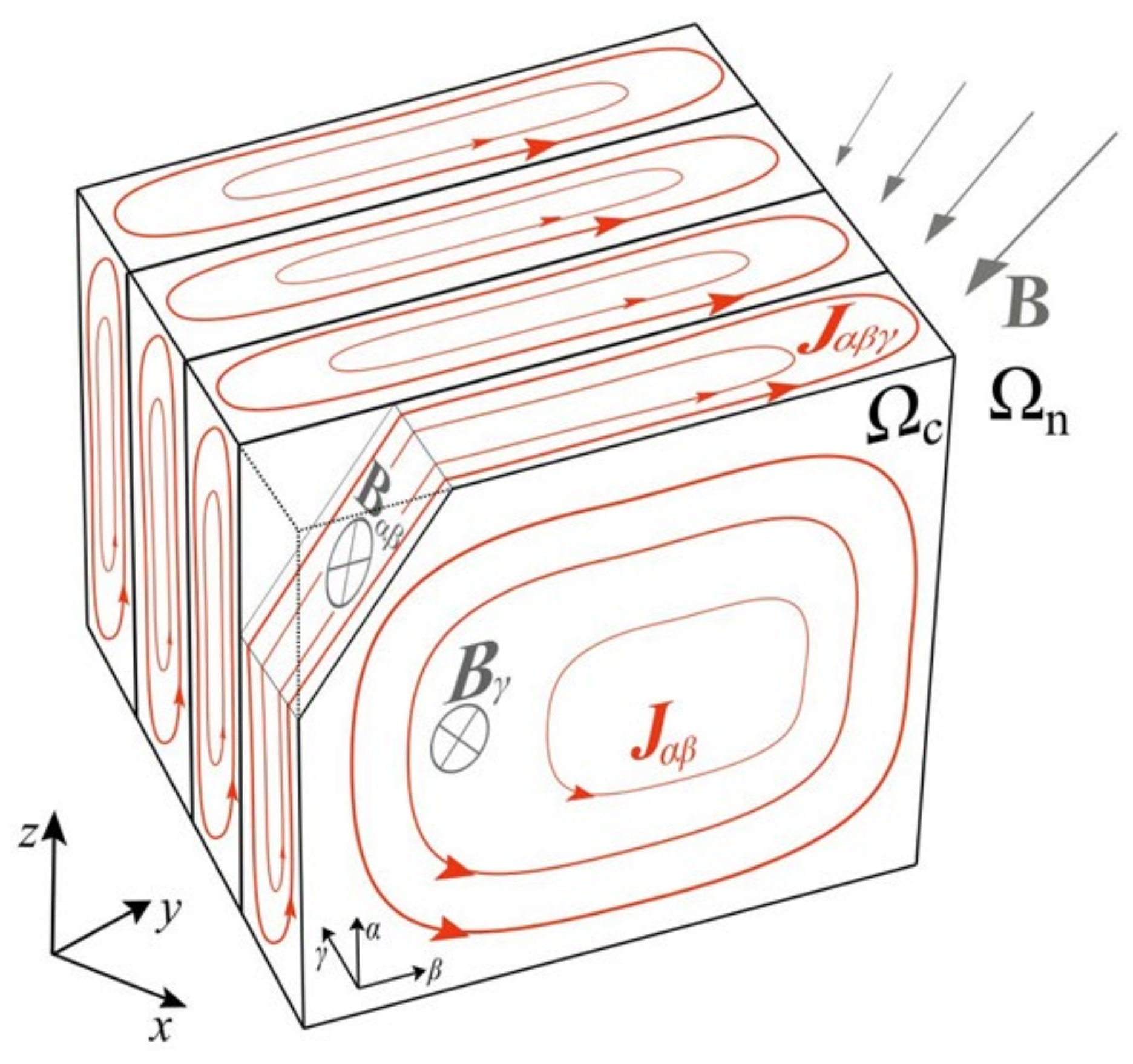
The focus of the paper is on the open-type transformer core, which belongs to a set of simply connected laminated media, such as the one shown in Figure 1. The problem of eddy currents in an open-type transformer core is characterized by certain specifications which are not necessarily present in the case of a closed-type transformer core. In the open-type core, eddy currents of density J are mostly concentrated in the outer lamination sheets. Furthermore, in the outer lamination sheets of the open-type core, eddy currents J are predominantly induced by the perpendicular component of the magnetic induction B , with respect to the lamination sheets. On the other hand, towards the interior of the open-type core, eddy currents J are predominantly induced by the tangential component of the magnetic induction B , with respect to the lamination sheets. It is then useful to separate the normal and tangential components of magnetic induction B and the eddy current density J in the calculation itself. Therefore, in the local orthogonal αβγ-coordinate system of a single lamination sheet shown in Figure 1, induction B can be written as the sum of the normal component B γ and the tangential component B α β with respect to the lamination sheet, that is
B = B γ + B α β ,
In accordance with (6), two corresponding equations follow from (1):
× ρ J α β = t B γ ,
× ρ J α β γ = t B α β ,
where J = J α β + J α β γ holds. According to (7), the component of the magnetic induction perpendicular to the lamination sheets induces the current density J α β , which only has tangential components with respect to the lamination sheets. On the other hand, the tangential component of magnetic induction, according to (8), induces eddy currents of density J α β γ which generally have all three spatial components, as shown in Figure 1.
Although the J α β γ and J α β are coupled, it is a good approximation to simulate them separately [11]. Because the value of magnetic permeability of the core is significantly lower in the perpendicular than in the tangential direction (with respect to the lamination sheets), J α β γ has a negligible effect on B γ , and consequently (according to (7)) a negligible effect on J α β .
Therefore, it is possible to ignore J α β γ when calculating J α β ; the reverse is not valid because the influence of J α β on B α β is not always negligible.
Because the open-type transformer core is surrounded by a medium of low magnetic permeability (air), a large proportion of the total magnetic flux enters the core perpendicular to the lamination sheets; thus, J α β is usually several times larger than J α β γ in the outer lamination sheets, which further reduces the importance of considering J α β γ when calculating J α β . Therefore, in contrast to the closed-type core, the losses due to J α β usually represent a major part of the total eddy current losses in the open-type core [12,13]. In this paper, the emphasis is therefore on the method of calculating the eddy current density J α β , i.e., losses due to J α β . Hence, J α β γ will be neglected in the first simulation step when calculating J α β , and it can be calculated in the second simulation step [14,15], or only the losses due to J α β γ can be calculated in the post-processing [3].

3. Specifications of the Laminated Open-Type Core

As previously described, in the case of the open-type core, J α β usually has a significantly higher value in the outer lamination sheets compared to J α β γ , and the total eddy current losses due to J α β are several times larger than the total losses due to J α β γ . In order to reduce the value of J α β , it is desirable to reduce the surface area of the lamination sheets. Some of the engineering options are to assemble the open-type core from several smaller, more slender lamination stacks, and/or to use heterogeneous stacking directions for the lamination sheets [10,16]. 
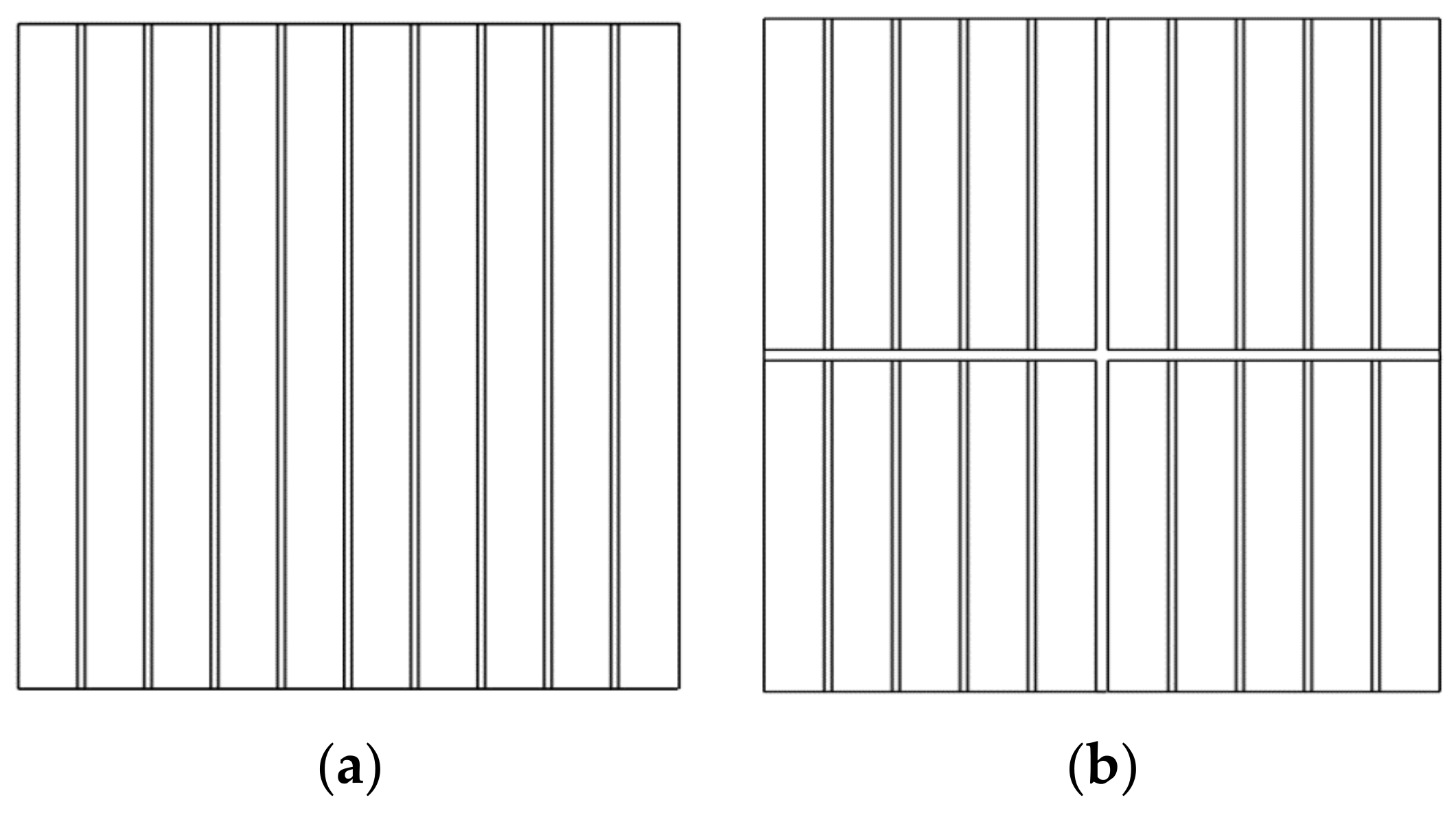
Figure 2 shows a comparison of the cross-sections of the standard (one-part) core and the multipart core composed of four slenderer cores.
The Ω c region of the open-type core shown in Figure 2a is without region partitions, i.e., Ω c = Ω c 1 , as denoted in Figure 3a. On the other hand, the Ω c region of the multipart open-type core shown in Figure 2b consists of the individual parts of the core Ω c , i , where every two adjacent parts of the core Ω c , i and Ω c , j are mutually isolated by an insulation layer Ω ins , i - j , i.e., Ω c = ( Ω c , 1 Ω c , n ) ( Ω ins , 1 - 2 Ω ins , i - j ) , as denoted in Figure 3b.
Again, as in the case of a standard one-part open-type core, each part of the multipart core consists of a laminated ferromagnetic part Ω lam , i and the associated insulation region Ω ins , i , that is, Ω c , i = Ω lam , i Ω ins , i . Because the open-type core is topologically simply connected, some other configurations of the parts of the multipart core in Figure 2b are easily feasible. To enable open-type transformer core optimization, the developed method should be able to simulate eddy currents for all possible configurations.

4. Homogenization of the Laminated Open-Type Core

An extremely dense finite element mesh, especially in the γ-direction, can be avoided by homogenizing the material characteristics of the Ω c region, thus obtaining the Ω ¯ c region. The homogenization of the electrical and magnetic characteristics of a laminated medium with a fill factor k f yields the anisotropic characteristics of the material, with the diagonal tensors of electrical resistivity ρ and magnetic reluctivity ν being defined as
ρ = ρ α ρ β ρ γ ,
ν = ν α ν β ν γ .
As was already stated, only (2) and (7) are modeled in the first simulation step, whereas the fields in (8) are neglected. The values of all of the fields in (2) and (7) change monotonically in the γ-direction, and therefore the components of ρ and ν defined in (9) and (10) are calculated using the following well-known Formula [11]:
ρ α = ρ β = ρ lam k f 1 ,
ρ γ 1 ρ ins 1 0 ,
ν α 1 = ν β 1 = k f ν lam 1 + ( 1 k f ) ν ins 1 ,
ν γ = k f ν lam + ( 1 k f ) ν ins .
Note that, due to (12), eddy current density J α β γ goes approximately to zero, and consequently, the fields in (8) will approximately be equal to zero.
In the case of a multipart open-type core, Ω c region homogenization is carried out by applying (9)–(14) to each Ω c , i part of the multipart core separately, with interface surfaces Γ ins , i - j instead of Ω ins , i - j layers between them. Therefore, each homogenized part Ω ¯ c , i will be assigned its ρ i and ν i tensors. However, for the thin insulating region Ω ins , i - j to be homogenized and modeled as the interface surface Γ ins , i - j between the two adjacent core parts ( Ω ¯ c , i and Ω ¯ c , j region), at least one of the two core parts must have a component of the tensor ρ i equal to zero in the direction perpendicular to the interface surface Γ ins , i - j , in order to prevent the flow of eddy currents from Ω ¯ c , i to the Ω ¯ c , j region. If this is not the case, the direct modeling of Ω ins , i - j is one of the options. However, a much denser mesh within and around the Ω ins , i - j region is then needed, which significantly slows down the simulation convergence. For the multipart core shown in Figure 2b, i.e., in Figure 3b, regions Ω ins , 1 - 4 and Ω ins , 2 - 3 cannot be modeled as Γ ins , 1 - 4 and Γ ins , 2 - 3 .
A much more economical and simpler approach is to use a formulation based on the current vector potential T , approximated by the edge elements. In this case, instead of the direct modeling of the insulation regions Ω ins , i - j , it is possible to only prescribe the interface condition T × n = 0 on the surface Γ ins , i - j between two parts of the multipart core, where n is perpendicular to the surface Γ ins , i - j . This ultimately prevents the penetration of eddy currents from one part of the core into another, because J n = × T n = ( T × n ) = 0 holds. Hence, a T -based formulation, such as a T , φ φ formulation, is a better choice for the modeling of eddy currents in an open-type laminated core, where φ represents the magnetic scalar potential. On the other hand, the T , φ φ formulation does not ensure the exact continuity of the magnetic induction component B γ at the interface between the core and the surrounding air, but this continuity is ensured only in a weak sense. This is a problem, because to accurately calculate J α β , according to (4), it is necessary to accurately calculate B γ . If the magnetic vector potential A , approximated by the edge elements, is used instead of φ, the continuity of B γ at the air-core interface is ensured in a strong sense. Therefore, a method for the calculation of the eddy currents described in this paper will be based on the A , T A formulation, which uses A and T in the core, and only A in the surrounding region [17,18].

5. The Weak A , T - A Formulation

According to (3) and (4), the current density J and magnetic induction B are solenoidal fields, so it follows that
J = × T ,
B = × A ,
and the source current density J s is also a solenoidal field, so it holds that
J s = × T .
In order to ensure the consistency of the left-hand side and the right-hand side of the future matrix, Equation (17) will be used instead of J s [19]. By including (15)–(17) in (1) and (2), a formulation of the eddy current problem in Ω ¯ c is obtained as:
× ρ × T + t ( × A ) = 0 ,
× ν × A × T = × T s .
Similarly, by including (16) and (17) in (5), a formulation in Ω n follows:
× ν n × A = × T s .
As shown in Figure 4, region Ω ¯ c is enclosed by surface Γ nc , which represents the interface between regions Ω ¯ c and Ω n . The interface conditions between the fields in Ω n and Ω ¯ c must be satisfied on Γ nc , i.e.,
B n n n + B c n c = 0 ,
H n × n n + H c × n c = 0 ,
J n n n + J c n c = 0 ,
where the exponents “n” and “c” denote fields in the Ω n and Ω ¯ c parts of the domain, respectively. The continuity of the normal component of magnetic induction B is exactly preserved, because A is approximated with edge elements, i.e., (21) is automatically satisfied at Γ nc . Condition (22) can be written as H n × n n + H c × n c = ν B n × n n + ν B c × n = 0 , i.e., it is necessary to prescribe the interface condition on Γ nc as
( ν × A n ) × n n + ( ν × A c ) × n c = 0 .
Because J n = 0 by definition, from (23) it follows that J c n c = 0 , and using (15) it follows that J c n c = × T c n c = ( T c × n c ) = 0 . The boundary condition is then prescribed on Γ nc as
T × n c = 0 .
The boundary conditions must also be defined on Γ B and Γ H , where Γ B and Γ H are the disjointed outer boundaries of Ω n , as shown in Figure 4. The surface Γ B represents the surface on which (26) holds, while Γ H represents the surface on which (27) holds, i.e.,
B n n = 0 ,
H × n n = 0 .
For the sake of conciseness and without a lack of generality, it will be assumed below that Γ H is not present, i.e., the entire outer surface of Ω n is Γ B . The boundary condition (26) is valid for a sufficiently distant boundary Γ B . Because B n = × A n = ( A × n ) = 0 holds, from (26) it follows that the homogeneous Dirichlet boundary condition on Γ B is
A × n n = 0 .
In order for the coefficient matrix to be symmetric, a time-primitive vector field τ is used instead of T , i.e., T = t τ [20]. Using (19), (20) and interface condition (24), the first equation of the weak A , T A formulation is obtained:
Ω n ν n × A × N i d Ω + Ω ¯ c ν × A × N i d Ω + Ω ¯ c × t τ N i d Ω = Ω n T s × N i d Ω + Ω ¯ c T s × N i d Ω ,
From (18) follows the second equation of the weak A , T A formulation:
Ω ¯ c t A × N i d V Ω ¯ c ρ × t τ × N i d V = 0 .
In (29) and (30), N i represents both the edge basis functions (for the interpolation of A and τ ) and weighting functions. Notice that the coefficient matrix for the weak Galerkin formulation (29) and (30) makes a consistent and symmetric system of equations.

6. Elimination of Degrees of Freedom

Because the A , T A formulation uses two vector potentials in Ω ¯ c , the total number of degrees of freedom in Ω ¯ c is 2 n e , where n e represents the total number of edges in the finite element mesh in Ω ¯ c . This is significantly more degrees of freedom compared to the formulations that use one vector and one scalar potential in Ω ¯ c and have a total of n e + n n degrees of freedom in Ω ¯ c , where n n is the number of nodes in the finite element mesh in Ω ¯ c . A higher number of degrees of freedom adversely affects the working memory and duration of the simulation.
Because J α β γ is neglected when calculating J α β , the current vector potential T should only define J α β in (15). Thus, in an orthogonal αβγ-coordinate system defined locally within a lamination sheet, where the γ-direction represents the normal direction of the lamination sheet, (15) can be written as
J α β = × T = β T γ a α α T γ a β .
As can be seen from (31), only T γ is needed, whereas the tangential components T α and T β are zero, and therefore redundant. If the right prismatic finite elements (wedge or hexahedron) with the base parallel to αβ plane and the height aligned with the γ-direction are used, then it is possible to geometrically decouple the degrees of freedom associated with the T γ component from the degrees of freedom associated with the T α and T β components, as shown in Figure 5. Because T is interpolated with edge basis functions, the degrees of freedom associated with the edges lying in the γ-direction then approximate only the T γ component, and the degrees of freedom associated with the edges belonging to the base of the element approximate T α and T β components.
In Figure 5, T i represents the degree of freedom associated with edge e i , and is calculated as a line integral of the current vector potential T along e i . Because each edge of a finite element is assumed to be either aligned with the γ-direction or parallel to the αβ plane, it is associated with either T i γ or T i α β . If the e i edge is aligned with the γ-direction, then it is associated with T i γ degree of freedom:
T i γ = e i T d l = e i ( T α a α + T β a β + T γ a γ ) a γ d l = e i T γ d l .
On the other hand, if the e i edge is parallel to the αβ plane, then T i α β follows as:
T i α β = e i T d l = e i ( T α a α + T β a β + T γ a γ ) ( a α d l α + a β d l β ) = e i T α d l α + e i T β d l β .
Because the T α and T β components are equal to zero, each T i α β degree of freedom should be equal to zero. In order to achieve this, surface condition T × n = 0 , which implies that T α = 0 and T β = 0 , can be given on the basis of the prismatic finite elements. Figure 6a shows a sequence of the prismatic (wedge) finite elements extruded in the γ-direction in three layers between the two interface surfaces Γ nc .
In order to set the surface condition T × n = 0 on the bases of finite elements, the tangential surfaces associated with the element bases are extruded together with the finite elements, as shown in Figure 6b. Thus, all of the T i α β degrees of freedom belong to one of the created tangential surfaces, as denoted by Γ t . Because setting T × n = 0 on Γ t fixes the values of T i α β degrees of freedom to T i α β = 0 , two-thirds of the total number of T i degrees of freedom are eliminated from the simulation.
In addition, (12) becomes redundant, i.e., the anisotropy of the electrical resistivity is already ensured by setting T × n = 0 on the Γ t surfaces.

7. Results and Discussion

Because it is based on the A , T A formulation with the elimination of redundant degrees of freedom using the T × n = 0 condition on the created Γ t surfaces, the method described in this paper will be referred to below as the ATAΓt method. In order to determine the validity and accuracy of the ATAΓt method, the simulation results were compared with the results of the brute force simulation (which will be referred to below as the BF method) on a small-size model. After that, the efficiency of the ATAΓt method was tested on a real-size open-type core model, by comparing the ATAΓt method with the homogenization method (expressions (9)–(14)), which is based on the A , V A Formulation.

7.1. Validation of the ATAΓt Method

For this purpose, a small-scale model consisting of an open-type core inside the coil, as shown in Figure 7, was used. The core is a laminated cuboid with a fill factor k f = 0.96 . It consists of 10 lamination sheets of thickness d = 0.48   mm . The magnetic reluctivity of the lamination is ν lam = 795   m / H and the electric resistivity is ρ lam = 4 10 7   Ω m . The source current density J s is sinusoidal, and is given by the source current vector potential T s . Because the coil has a regular geometry, the source current vector potential T s can be expressed analytically as
T s = J s w a z , in   the   coil   hole T s , c o i l a z , inside   the   coil 0 , elsewhere ,
where J s = 1   A / mm 2 represents the source current density amplitude, w represents the cross-sectional width of the coil, and T s , c o i l represents the current vector potential function that depends on the position inside the coil; for this model, it is calculated as:
T s , c o i l = J s ( R 2 x ) , | y | < l c / 2 J s R 2 x 2 + ( y + l c / 2 ) 2 , y < l c / 2 J s R 2 x 2 + ( y l c / 2 ) 2 , y > l c / 2 ,
where R 2 = 0.85   cm represents the outer radius of the coil, as shown in Figure 7b.
The BF simulation was performed on the laminated model shown in Figure 7. In order to achieve a sufficiently fine discretization of the lamination sheets and insulation layers, an extremely dense FE mesh was required, with a total of 5 million elements. In contrast, the ATAΓt method was performed on the homogenized core model (calculated with (9)–(14)), with a total of 100,000 elements. The visualization of the Joule field (the eddy current loss density field) at 50 Hz for the BF simulation is shown in Figure 8, and visualization of the Joule field at 50 Hz for the ATAΓt simulation is shown in Figure 9. There is a very good agreement of the Joule fields in Figure 8 and Figure 9.
The ratio of the eddy current losses obtained by the ATAΓt method and BF method, at different frequencies, is shown in Figure 10. Curve P α β shows the ratio for P α β losses, and curve P α β γ shows the ratio for P α β γ losses, whereas the ratio for the total eddy current losses P is represented by the P curve. According to the P α β curve in Figure 8, there is a very good agreement in the values of P α β between the BF and ATAΓt simulation results, thus validating the ATAΓt method. It is important to emphasize that the curve P α β is the same even in the case when the elimination of the degrees of freedom on Γ t surfaces is not performed, i.e., the elimination of the degrees of freedom has no effect on the simulation results other than the improvement of the simulation convergence rate. According to the P α β γ curve in Figure 10, there is a good enough agreement in the values of P α β γ , especially at lower frequencies.
In the post-processing phase of the ATAΓt simulation, the losses P α β are directly calculated from J α β , whereas the losses due to J α β γ are calculated indirectly from the tangential component of induction B α β using the well-known formula P α β γ = σ π 2 f 2 d 2 B α β 2 / 6 [21]. For a more accurate calculation of P α β γ losses, it is possible to use a different method that is compatible with the A , T A formulation [14,15]; in this paper, the emphasis is on eddy currents J α β and the associated losses P α β .

7.2. Testing the Efficiency of the ATAΓt Method

In order to test the effectiveness of the ATAΓt method, it is necessary to analyze the behavior of the ATAΓt method on a model that is comparable in size to the actual open-type cores. Here, the ATAΓt method is compared with the homogenization method (9)–(14) that is based on the standard A , V A formulation (the AVA method below). The simulation model consists of a laminated open-type (I-shaped) core within the cylindrical coil, the frontal section of which is shown in Figure 11a. The lamination consists of 100 lamination sheets and has a fill factor k f = 0.95 . The magnetic reluctivity of the lamination is ν lam = 795   m / H and the electric resistivity is ρ lam = 4 10 7   Ω m . Figure 11b shows a homogenized cross-section of the core in the case of a standard, one-part core, and Figure 11c shows a homogenized cross-section of the core in the case of a multi-part core (a two-part core, in this case). The simulation was performed on both the one-part core model (hereinafter marked by 1C-model) and the two-part core model (hereinafter marked by 2C-model).
The source current is sinusoidal, with an amplitude of the uniform current density J s given by the current vector potential T s . Because the coil is cylindrical, the current vector potential T s is defined analytically as
T s = J s w a z , in   the   coil   hole J s x 2 + y 2 R 2 a z , inside   the   coil 0 , elsewhere
where J s = 1   A / mm 2 , w = 3   cm and R 2 = 8.5   cm .
In the case of the 1C-model, the FE mesh is the same for both the ATAΓt and AVA simulation, whereas in the case of the 2C-model it is necessary to create the insulation layer Ω ins , 1 - 2 between the two parts of the core, but the number of finite elements is similar for both types of FE mesh. The simulations were performed at four different levels of FE mesh density. There is a good agreement between the losses obtained by the ATAΓt and AVA methods in both the 1C-model case and the 2C-model case, as shown in Figure 12. As expected, the finer the FE mesh, the better the agreement.
However, a comparison of the convergence rates at all four levels of FE mesh density shows significant differences between methods, as can be seen in Figure 13 and Figure 14. In addition to the AVA and ATAΓt methods, the comparison in Figure 13 and Figure 14 also includes the ATAnotΓt method, which is a method based on the weak A , T A formulation (29) and (30), without elimination of redundant degrees of freedom, i.e., without imposing T × n = 0 on the Γ t surfaces. In the case of the 1C-model, the ATAnotΓt method is inferior to the AVA method, which can be explained by the higher number of degrees of freedom required in the case of the A , T A formulation. However, the ATAΓt simulation converges significantly faster than both AVA and ATAnotΓt simulations, as shown in Figure 13. In the case of the 2C-model, the convergence rate of AVA simulation is even slower than the convergence rate of ATAnotΓt simulation, as can be seen in Figure 14. Hence, modeling the insulation layer (region Ω ins , 1 - 2 ) between the two parts of the 2C-model core has a significant effect on the convergence rate of the AVA simulation. Again, the ATAΓt simulation converges much faster than the ATAnotΓt and AVA simulations. It is important to note that the simulation results for the eddy current losses are the same for the ATAΓt and ATAnotΓt simulations.

8. Conclusions

The open-type core has certain differences with respect to the closed-type core that are important when calculating eddy current losses. Because the eddy currents in a real-size open-type core are largely induced by the magnetic induction component perpendicular to the lamination sheets, the open-type core may have a multi-part structure in order to reduce the eddy current losses. In addition, fields and eddy current losses are mostly located in the outer lamination sheets, such that the design optimization of an open-type core may require even more irregular geometry. Consequently, the complete homogenization of such a core is often not possible. Despite a significantly higher number of degrees of freedom, the A , T A formulation offers the greatest flexibility in the optimization of the open-type transformer core with respect to eddy current losses. By creating an appropriate geometric model and FE mesh, it is possible to eliminate the redundant degrees of freedom of the current vector potential T , thus significantly improving the convergence rate of the eddy current simulations. Additionally, by eliminating the degrees of freedom in the A , T A formulation, it is also possible to prescribe the anisotropic electrical conductivity of an open-type core with heterogeneous lamination stacking directions and/or curved lamination sheets, assuming that they are simply connected. In future work, the ATAΓt method will be extended to the nonlinear case, and a comparison of the simulation results with the measurements will be made.

Author Contributions

Conceptualization, S.F. and B.T.; Data curation, S.F., B.T. and I.Ž.; Formal analysis, S.F.; Funding acquisition, B.T. and I.Ž.; Investigation, S.F., B.T. and I.Ž.; Methodology, S.F.; Project administration, B.T. and I.Ž.; Resources, B.T. and I.Ž.; Software, S.F.; Supervision, B.T.; Validation, S.F.; Visualization, S.F.; Writing—original draft, S.F.; Writing—review and editing, B.T. and I.Ž. All authors have read and agreed to the published version of the manuscript.

Funding

This work was funded in part by the Croatian Science Foundation under the project number IP-2020-02-2369.

Institutional Review Board Statement

Not applicable.

Informed Consent Statement

Not applicable.

Data Availability Statement

Not applicable.

Conflicts of Interest

The authors declare no conflict of interest.

References

  1. Hollaus, K.; Schöberl, J. Multi-scale FEM and magnetic vector potential A for 3D eddy currents in laminated media. COMPEL Int. J. Comput. Math. Electr. Electron. Eng. 2015, 34, 1598–1608. [Google Scholar] [CrossRef]
  2. Henrotte, F.; Steentjes, S.; Hameyer, K.; Geuzaine, C. Pragmatic two-step homogenisation technique for ferromagnetic laminated cores. IET Sci. Meas. Technol. 2015, 9, 152–159. [Google Scholar] [CrossRef]
  3. Kaimori, H.; Kameari, A.; Fujiwara, K.F.E.M. Computation of Magnetic Field and Iron Loss in Laminated Iron Core Using Homogenization Method. IEEE Trans. Magn. 2007, 43, 1405–1408. [Google Scholar] [CrossRef]
  4. Bíró, O. Edge element formulations of eddy current problems. Comput. Methods Appl. Mech. Eng. 1999, 169, 391–405. [Google Scholar] [CrossRef]
  5. Ren, Z.; Bouillault, F. Magnetodynamic Formulations. In The Finite Element Method for Electromagnetic Modeling; Wiley-ISTE: London, UK, 2008; pp. 117–137. [Google Scholar]
  6. Dular, P.; Gyselinck, J.; Geuzaine, C.; Sadowski, N.; Bastos, J.P.A. A 3-D Magnetic Vector Potential Formulation Taking Eddy Currents in Lamination Stacks into Account. IEEE Trans. Magn. 2003, 39, 1424–1427. [Google Scholar] [CrossRef]
  7. Ziger, I.; Bojanic, B.; Krajtner, D. Open-core Power Voltage Transformer: Concept, properties, application. In Proceedings of the 2014 IEEE International Energy Conference (ENERGYCON), Cavtat, Croatia, 13–16 May 2014; pp. 246–253. [Google Scholar] [CrossRef]
  8. Žiger, I. Metoda proračuna gubitaka naponskih transformatora velike snage s otvorenom jezgrom. Ph.D. Thesis, Faculty of Electrical Engineering and Computing, University of Zagreb, Zagreb, Croatia, 2018. [Google Scholar]
  9. Orosz, T.; Pánek, D.; Karban, P. FEM Based Preliminary Design Optimization in Case of Large Power Transformers. Appl. Sci. 2020, 10, 1361. [Google Scholar] [CrossRef] [Green Version]
  10. Ziger, I.; Trkulja, B.; Stih, Z. Determination of Core Losses in Open-Core Power Voltage Transformers. IEEE Access 2018, 6, 29426–29435. [Google Scholar] [CrossRef]
  11. De Gersem, H.; Vanaverbeke, S.; Samaey, G. Three-dimensional-two-dimensional coupled model for eddy currents in laminated iron cores. IEEE Trans. Magn. 2012, 48, 815–818. [Google Scholar] [CrossRef]
  12. Cheng, Z.; Takahashi, N.; Forghani, B. TEAM Problem 21 Family (V. 2009). Int. Compumag Soc. Board Compumag. 2009, 2, 1–16. [Google Scholar]
  13. Cheng, Z.; Wang, X. Engineering-oriented Benchmarking and Application-based Magnetic Material Modeling in Transformer Research. J. Energy 2012, 61, 73–86. [Google Scholar]
  14. Bíró, O.; Preis, K.; Ticar, I. A FEM method for eddy current analysis in laminated media. COMPEL Int. J. Comput. Math. Electr. Electron. Eng. 2005, 24, 241–248. [Google Scholar] [CrossRef]
  15. Frljic, S.; Trkulja, B. Two-Step Method for the Calculation of Eddy Current Losses in an Open-Core Transformer. IEEE Trans. Magn. 2021, 57, 1–8. [Google Scholar] [CrossRef]
  16. Lapthorn, A.; Keenan, K. A Radially Laminated Core for Partial Core Transformers. In Proceedings of the EEA Conference & Exhibition, Wellington, New Zeland, 24–26 June 2015; University of Canterbury: Christchurch, New Zealand, 2015. [Google Scholar]
  17. Albertz, D.; Henneberger, G. On the use of the new edge based A–A,T formulation for the calculation of time-harmonic, stationary and transient eddy current field problems. IEEE Trans. Magn. 2000, 36, 818–822. [Google Scholar] [CrossRef]
  18. Van Riesen, D.; Kaehler, C.; Henneberger, G. Convergence behaviour of different formulations for time-harmonic and transient eddy-current computations in 3D. IEE Proc. Sci. Meas. Technol. 2004, 151, 434–439. [Google Scholar] [CrossRef]
  19. Ren, Z. Influence of the R. H. S. on the convergence behaviour of the curl-curl equation. IEEE Trans. Magn. 1996, 32, 655–658. [Google Scholar] [CrossRef]
  20. Albertz, D.; Henneberger, G. Calculation of 3D eddy current fields using both electric and magnetic vector potential in conducting regions. IEEE Trans. Magn. 1998, 34, 2644–2647. [Google Scholar] [CrossRef]
  21. Gyselinck, J.; Vandevelde, L.; Melkebeek, J.; Dular, P.; Henrotte, F.; Legros, W. Calculation of Eddy Currents and Associated Losses in Electrical Steel Laminations. IEEE Trans. Magn. 1999, 35, 1191–1194. [Google Scholar] [CrossRef]
Figure 1. Relevant fields on a simply connected laminated medium.
Applsci 11 11543 g001
Figure 2. Cross-sections of the two open-type cores: (a) the standard one-part core; (b) a multipart-core assembled from four more slender parts.
Applsci 11 11543 g002
Figure 3. Denoted regions on the cross-sections of the two open-type cores: (a) the standard one-part core; (b) a multipart-core assembled from four more slender parts.
Applsci 11 11543 g003
Figure 4. Problem domain for the calculation of the eddy currents in an open-type core. The homogenized region Ω ¯ c can be one-part or multipart. A one-part core is shown for the sake of clarity.
Applsci 11 11543 g004
Figure 5. Geometrical decoupling of the edge degrees of freedom for the current vector potential. All of the edges are either parallel to the γ-direction or parallel to the αβ plane. The degrees of freedom T 1 , T 2 , T 3 , T 7 , T 8 , and T 9 are parallel to the αβ plane, and are therefore redundant.
Applsci 11 11543 g005
Figure 6. A sequence of extruded finite elements: (a) without tangential surfaces Γ t ; (b) with tangential surfaces Γ t .
Applsci 11 11543 g006
Figure 7. Model for the brute force eddy current simulation: (a) 3D model sketch; (b) a quarter of the cross-section of the model. All of the dimensions are in centimeters.
Applsci 11 11543 g007
Figure 8. Joule field (density of the eddy current losses) in the laminated core of the model that is shown in Figure 7. The simulation results were obtained using the BF method at 50 Hz.
Applsci 11 11543 g008
Figure 9. Joule field (density of the eddy current losses) in the homogenized core of the model that is shown in Figure 7. The simulation results were obtained using the ATAΓt method at 50 Hz.
Applsci 11 11543 g009
Figure 10. The ratio of the eddy current losses obtained by the ATAΓt method to the eddy current losses obtained by the BF method.
Applsci 11 11543 g010
Figure 11. Homogenized real-size simulation model: (a) longitudinal section, (b) cross-section of the 1C model, (c) cross-section of the 2C model. All of the dimensions are in centimeters.
Applsci 11 11543 g011
Figure 12. Eddy current losses for the ATAΓt and AVA simulations at 50 Hz. The losses for 1C-ATAΓt and 1C-AVA are on the left axis. The losses for 2C-ATAΓt and 2C-AVA are on the right axis.
Applsci 11 11543 g012
Figure 13. Convergence rates for the simulations of the 1C model.
Applsci 11 11543 g013
Figure 14. Convergence rates for the simulations of the 2C model.
Applsci 11 11543 g014
Publisher’s Note: MDPI stays neutral with regard to jurisdictional claims in published maps and institutional affiliations.

