Article

Effect of Joint Characteristics and Geometries on Tunnel-Type Anchorage for Suspension Bridge

1
Department of Geotechnical Engineering Research, Korea Institute of Civil Engineering and Building Technology, Goyang 10223, Korea
2
Department of Civil Engineering, Chungnam National University, Daejeon 34134, Korea
*
Author to whom correspondence should be addressed.
Appl. Sci. 2021, 11(24), 11688; https://doi.org/10.3390/app112411688
Submission received: 11 November 2021 / Revised: 6 December 2021 / Accepted: 7 December 2021 / Published: 9 December 2021
(This article belongs to the Special Issue Design of Special Structures for Lateral Loads)

Abstract

:
In this study, the pull-out behavior of a tunnel-type anchorage was examined by considering both geometric and rock joint characteristics. Three-dimensional finite element analyses were performed with reference to the tunnel-type anchorage cases designed and constructed in Korea. The factors influencing the anchorage response were analyzed: the enlarged part, anchorage spacing, joint orientation, spacing, and the shear strength of the rock joints. According to the numerical studies, the size of the enlarged part influenced the failure shape of the tunnel-type anchorage. It was found that the anchorage spacing, the relationship between the tunnel-type anchorage, and the joint orientation and spacing greatly influenced the pull-out behavior of the anchorage. Additionally, the friction angle had a larger impact on the anchorage’s pull-out resistance than the cohesion between the rock joints.

1. Introduction

Cable-supported bridges are classified into cable-stayed and suspension bridges. Suspension bridges are one of the main types of long-span bridges [1,2] and possess significant benefits in terms of material properties and height-span ratio of the stiffening girders [3]. Suspension bridges are comprised of main beams, tower piers, cables, and anchorages, with the anchorages playing the major role in anchoring the suspension bridge’s main cables [4]. Based on the main cable anchoring method, suspension bridges are classified into self-anchored or earth-anchored. In a self-anchored bridge type, the main cable is directly attached to the stiffening girder, whereas in the earth-anchored type, the main cable is directly attached to the bridge via anchorages at the beginning and end locations. Anchorages are vital parts of earth-anchored suspension bridges, and support the tension of the main cables [4,5].
Anchorages for earth-anchored suspension bridges can be classified into gravity and tunnel types (Figure 1). The gravity type has a simple bearing mechanism by considering the weight of the concrete body as a factor of support. However, the gravity type has the disadvantage of requiring a huge amount of concrete and excavation. The tunnel type involves a method wherein the cable load is supported by excavating a tunnel in a relatively good rock mass. Subsequently, the tension member and concrete are filled in the excavated spot, making use of the frictional and cohesion resistance produced by the self-weight of the body and the front soil layer. The tunnel type design offers advantages because it is economical and minimizes environmental degradation of the surrounding environment compared to the gravity type [6].
The majority of the research conducted on suspension bridges is currently focused on bridge design technology [7,8], the dynamic response of structures under load [9,10], and bridge monitoring and structural reliability evaluation [11,12]. In contrast, there have only been a few studies analyzing suspension bridge anchorages [13].
Tunnel-type anchorages are rarely used in design, and their behavior when subjected to a pull-out load has still not been determined. Tunnel-type anchorages have mechanical characteristics similar to uplift piles and rock anchors [3]. Several model experiments and numerical simulations have been performed to investigate the mechanical behavior of uplift piles [14,15,16,17,18,19,20,21,22,23]. However, because the structures differ in shape, size, and material, it is difficult to relate the failure mode of the uplift pile to the failure mode of anchoring. Seo et al. [24] analyzed the failure mode from the initial stage to the failure stage of the tunnel-type anchorage through a two-dimensional small-scaled model test and image processing, and confirmed that the failure mode of the tunnel-type anchorage exhibited a wedge-shape. Additionally, the presence of discontinuities, such as joints and artificial and naturally occurring faults, influence the failure mode of tunnel-type anchorages [3]. However, there has been little study examining tunnel-type anchorages in relation to rock joint properties and geometry.
The purpose of this study was to evaluate the pull-out behavior of tunnel-type anchorages based on geometric and rock joint characteristics. A series of finite element (FE) analyses of tunnel-type anchorages were carried out. The enlarged part, anchorage spacing, joint orientation, joint spacing, and the shear strength of the rock joints were investigated and considered as the factors influencing pull-out behavior.

2. Numerical Analysis

2.1. Finite Element Mesh and Boundary

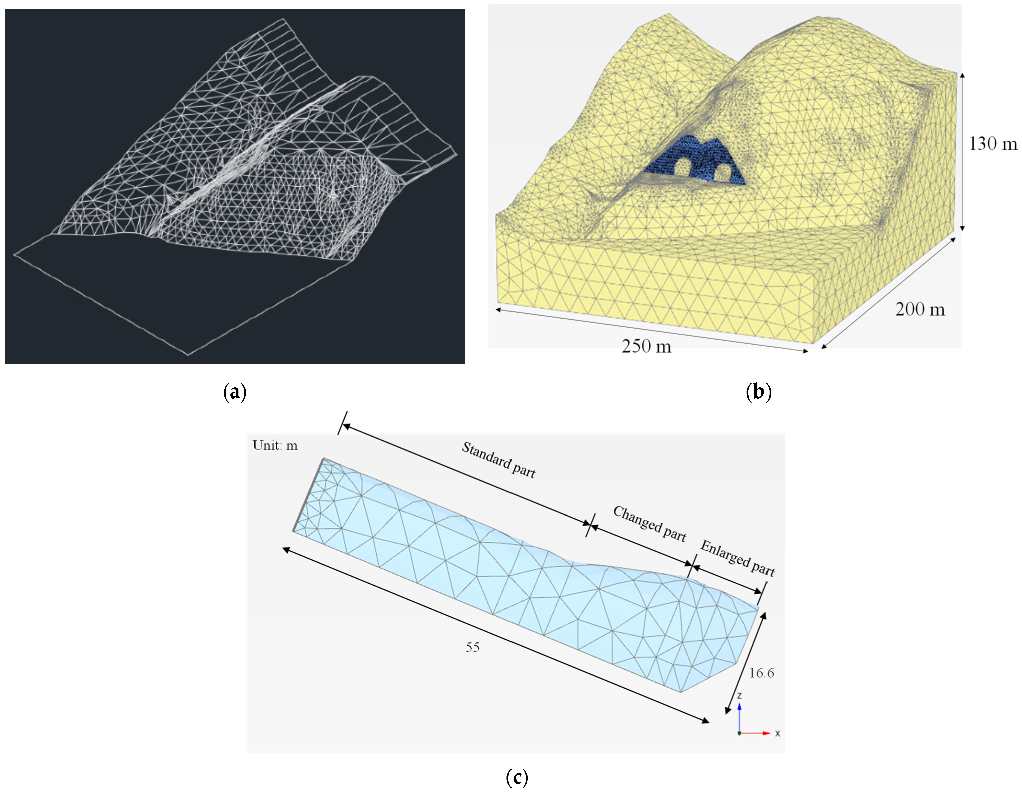
Three-dimensional conditions were used to model the tunnel-type anchorage and the surrounding rock. A commercial FE analysis software package, PLAXIS 3D [25], was used for this study. The analysis was conducted on Ulsan Grand Bridge, the only tunnel-type anchorage constructed in Korea. Figure 2 shows the typical 3D FE model used in this study. The mountainous area where the tunnel-type anchorage was constructed and the anchorage itself were modeled in the same shape using the design drawings (Figure 2a). The tunnel-type anchorage and soil were modeled with finite elements, enabling rigorous treatment of the soil–structure interactions. The soil and tunnel-type anchorage elements were 10-node wedge elements and 10-node tetrahedrons in the vertical direction. The outside of the anchorage and rock joint was modeled through interface elements. The interfaces were comprised of 10-node interface elements constituting of eight pairs of nodes, compatible with the 10-node-tetrahedrons side of the soil element. The interface elements had a 3 × 3 point Gaussian integration, which allowed differential displacements between the node pairs (slipping and gapping).
Mesh convergence studies were initially performed to determine the optimal mesh size required for analytical accuracy and computing efficiency. Figure 3 shows the load–displacement curves of the tunnel-type anchorages and the mesh information for different mesh densities. Finer mesh density was employed near the rock and anchorage interface zone, whereas coarser mesh was used closer to the boundary. The minimum size of all the meshes was the same 0.06093 m. The maximum size of all the meshes ranged from 27.51 m to 61.87 m. The mesh size reduced from Mesh 1 to Mesh 5; conversely, mesh density rose from Mesh 1 to Mesh 5. Meshes 4 and 5 had the same ultimate resistance, as illustrated in Figure 3, implying that the size of Mesh 4 had reached mesh convergence. As a result, Mesh 4 was employed for all studies.

2.2. Material Parameters and Interface Modeling

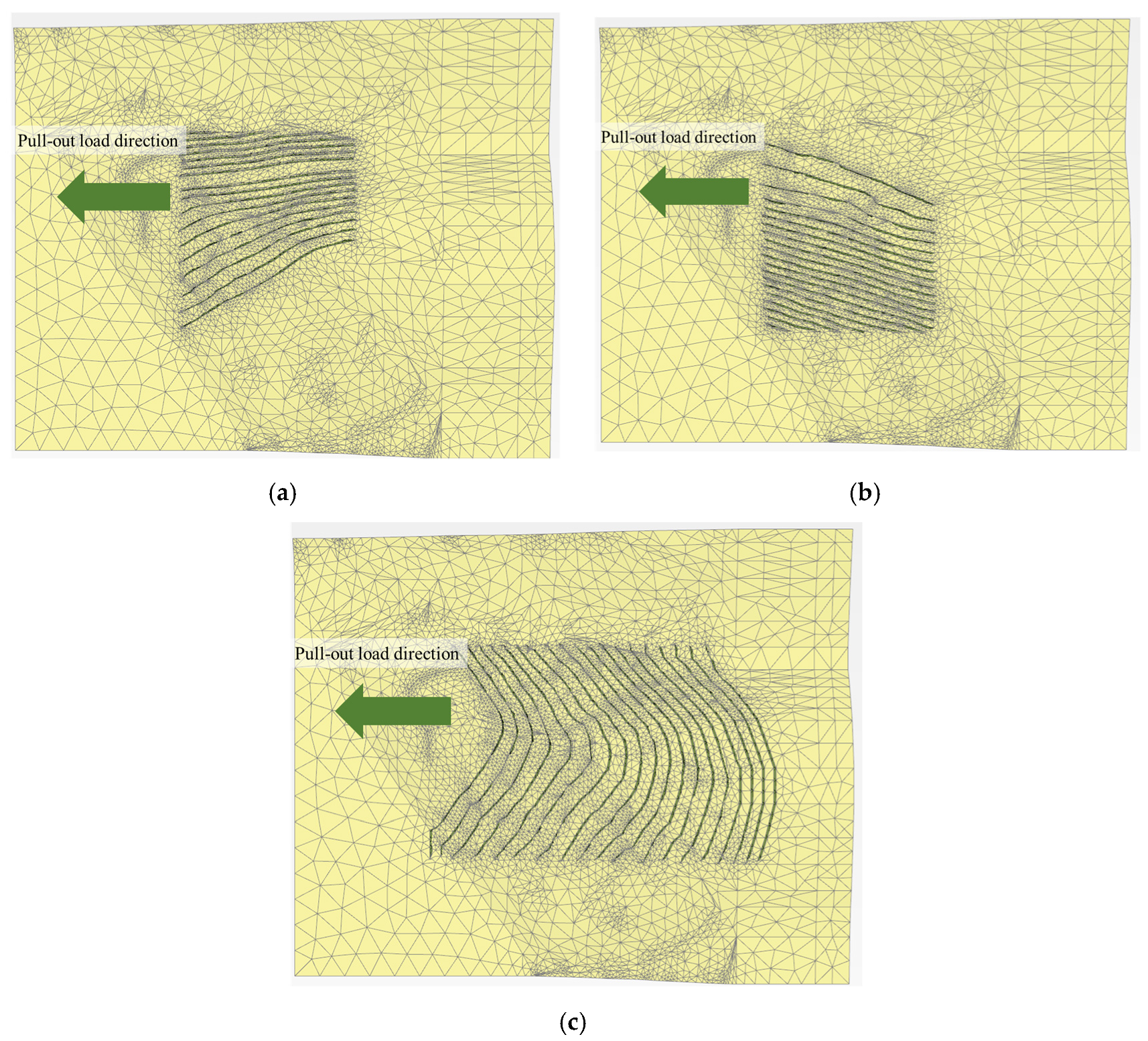
The anchorage was considered as a rigid body at all times in order to prevent the local failure of the anchorage due to the cable load. For the surrounding soil and rock layer, the Mohr–Coulomb non-associated flow rule was adopted. The interface element modeled by the bilinear Mohr–Coulomb model was employed to simulate the anchorage–soil interface. The interface element was treated as a zone of virtual thickness and behaved as an element with the same material properties as the adjacent soil elements before the occurrence of slipping. A low value of shear modulus was assigned to the interface element when the slip mode occurred in the interface element. To model the joint plane in the continuum analysis, all the joints were modeled as interfaces. The elastic interface normal stiffness (Kn) and the elastic interface shear stiffness (Ks) were applied to the stiffness of the interface. Based on the geotechnical investigation report of Ulsan Bridge, the physical properties of the soil, rock, and joints were applied and are shown in Table 1 and Table 2. Three main joint groups appearing in the rock surrounding the tunnel-type anchorage of Ulsan Bridge were selected, and the material properties of each major joint group (as shown in Table 2) were applied to the numerical analysis with reference to the design report. Figure 4 shows the FE mesh applied as an interface with the joint surface.

2.3. Parametric Study

Parametric studies were conducted to investigate the influence of the pull-out behavior on the tunnel-type anchorage based on the geometric and rock joint characteristics. From the numerical analysis results, the load-horizontal displacement curves of the tunnel-type anchorage were analyzed based on the geometric and rock joint characteristics.
A series of FE analyses on the tunnel-type anchorage in rock was performed using the influential parameters: the size of the enlarged part, anchorage spacing, joint dip/dip direction, joint spacing (s), the internal friction angle of the joint (ϕ), and the cohesion of the joint (c). These values are summarized in Table 3. The cable pull-out loads were applied using displacement control. As the displacement changes incrementally in a displacement-controlled analysis, a load–displacement curve could be derived.
Figure 5 shows the enlarged height and spacing of the tunnel-type anchorage used for numerical analysis. The diameter of the tunnel-type anchorage constructed in the Ulsan Grand Bridge is 10.85 m. The enlarged heights applied to the 3D numerical analysis were H = 0.0 m, H = 2.0 m, H = 4.0 m, H = 6.0 m, and H = 8.0 m. Additionally, the installation spacings of the tunnel-type anchorage applied to the 3D numerical analysis were 18.5 m, 23.5 m, and 28.5 m.

3. Results and Discussion—Geometric Conditions

3.1. Effect of the Enlarged Part

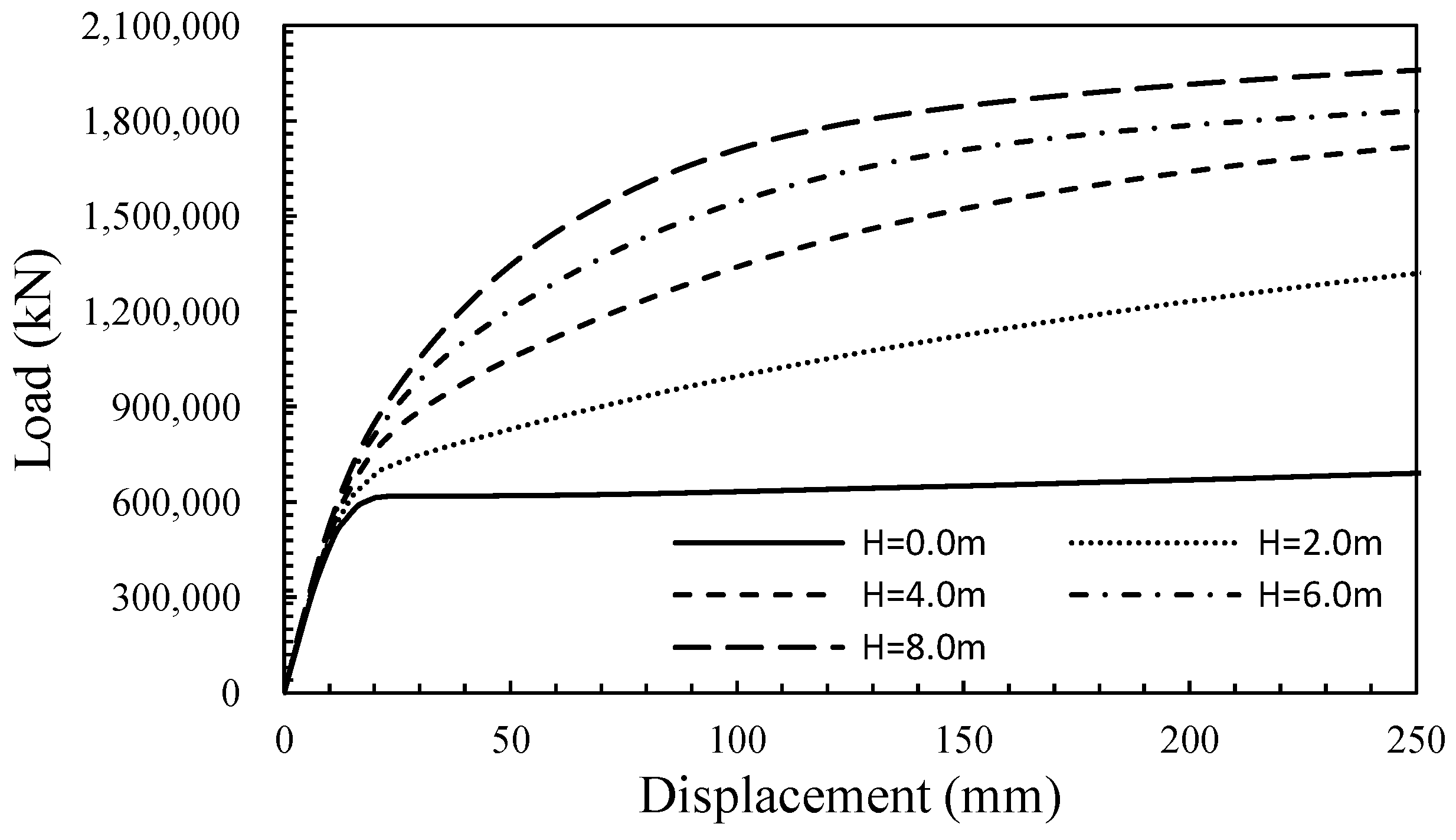
Figure 6 shows the load-horizontal displacement curve based on the enlarged height. The yield load was calculated by the load (P)–displacement (S) method, and the failure load was selected as the load at the maximum allowable displacement (195.5 mm) of the cable. The maximum allowable displacement of the Ulsan Grand Bridge–with its span length of 1150 m–was calculated as follows: maximum allowable displacement = 0.017 × span length = 0.017 × 1,150,000 mm = 195.5 mm. As shown in Figure 6, the failure load rapidly increased due to the installation of the enlargement H. When the enlarged height was 4.0 m or higher, the rate of increase of the failure load slowed down.
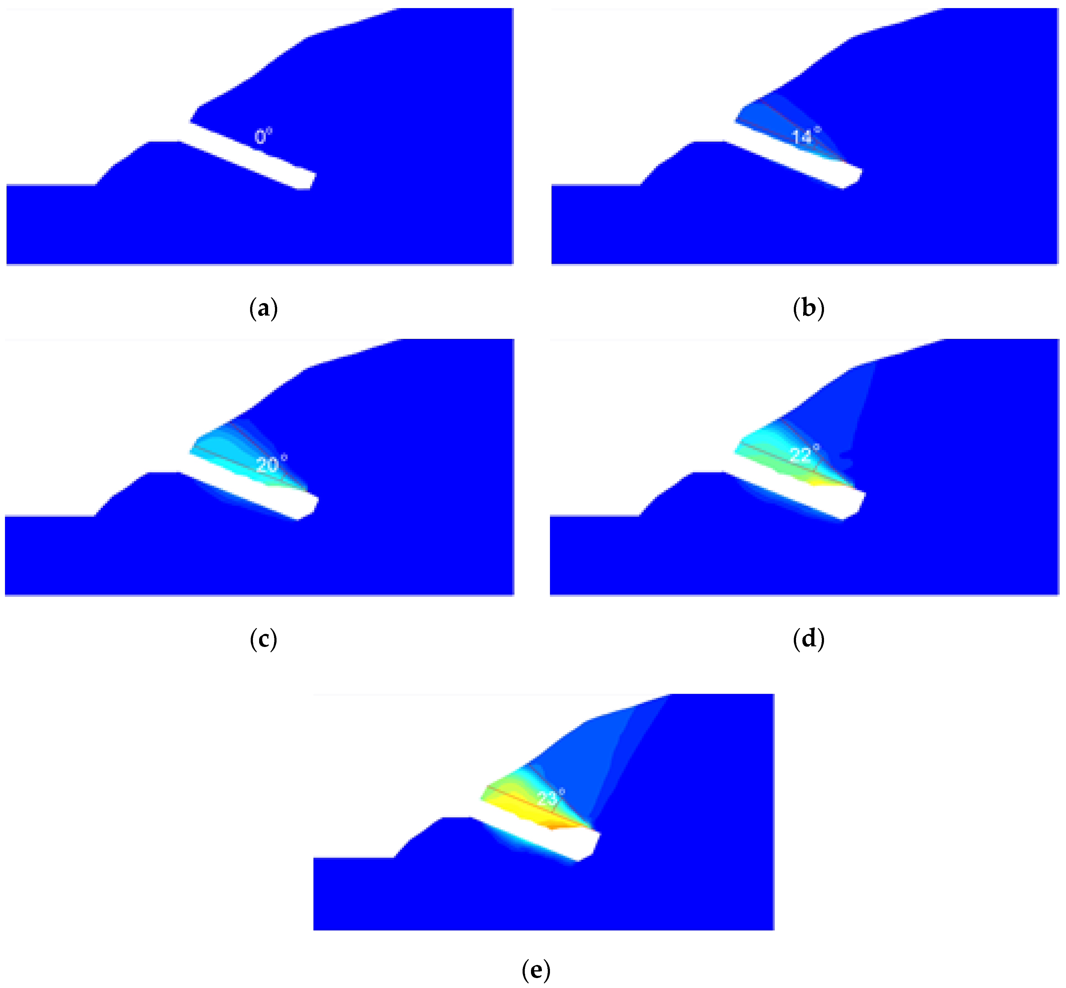
Figure 7 shows the surrounding soil failure mode and the angle based on the enlarged height of the tunnel-type anchorage. The failure angle refers to the angle made between the boundary surface of the surrounding rock (which was in parallel to the load-applied direction) and the failure surface in the enlargement of the tunnel-type anchorage. When the enlarged height of the anchorage was 0 m, the failure angle was 0°, exhibiting a pull-out failure shape. The results reveal that enlarged heights of 2.0 m, 4.0 m, 6.0 m, and 8.0 m had failure angles of 14°, 20°, 22°, and 23°, respectively, and their failure shape was a wedge. When the wedge failure angle increases, the pull-out resistance of the anchorage due to the pull-out load of the cable also increases, thereby ensuring the stability of the anchorage. The ratio increase values (failure angle for each enlarged height/failure angle at 2.0 m of the enlargement height) of the failure angle based on the enlarged height were 1.0, 1.43, 1.57, and 1.62. When the enlarged height was 4.0 m, the ratio of the failure angle increased by 43%; however, the ratio increase of the failure angle above the enlargement height of 4.0 m decreased to 57% and 62%.

3.2. Effect of Anchorage Spacing

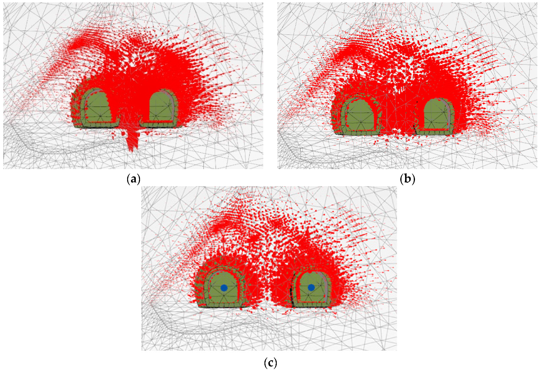
Figure 8 shows the load–horizontal displacement curve based on the installation spacing between the tunnel-type anchorages. Based on the load–horizontal displacement curve, the yield and failure loads were calculated. It was found that as the installation spacing between the tunnel-type anchorages widened, the failure load increased continuously; however, no significant increase was noticed in the yield load and the allowable horizontal displacement. Figure 9 shows the displacement vectors by an installation spacing between the tunnel-type anchorages. It was found that as the installation spacing between the tunnel-type anchorages became narrower, the displacement vector became more intensely concentrated in places between the anchorages, i.e., the failure load decreased due to group effect in the tunnel-type anchorage.

4. Results and Discussion—Joint Characteristics

4.1. Effect of Joint Orientation

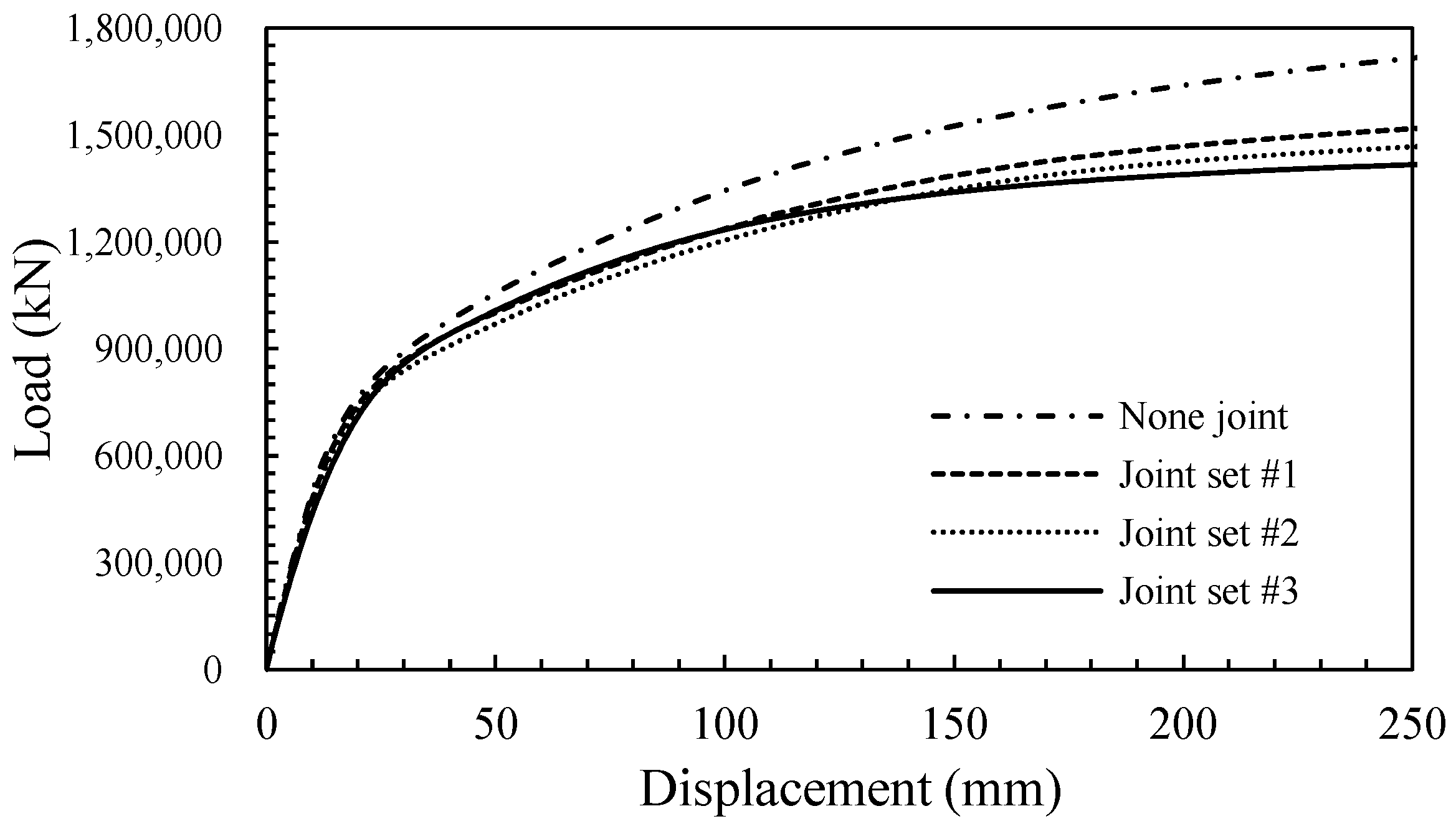
Figure 10 shows the load–horizontal displacement curve based on the direction of the rock joint. It was confirmed that the ultimate load was the largest in the case of no joint, and joint #3 (the joint direction perpendicular to the direction of application of the cable load) showed the smallest ultimate load. Through these results, it could be confirmed that the direction of the joint greatly affected the pull-out behavior of the tunnel-type anchorage. Since the failure mode of the tunnel-type anchorage appeared in a wedge shape, the ultimate load when there was a joint in the direction perpendicular to the cable load similar to the failure shape was considered small.

4.2. Effect of Joint Spacing

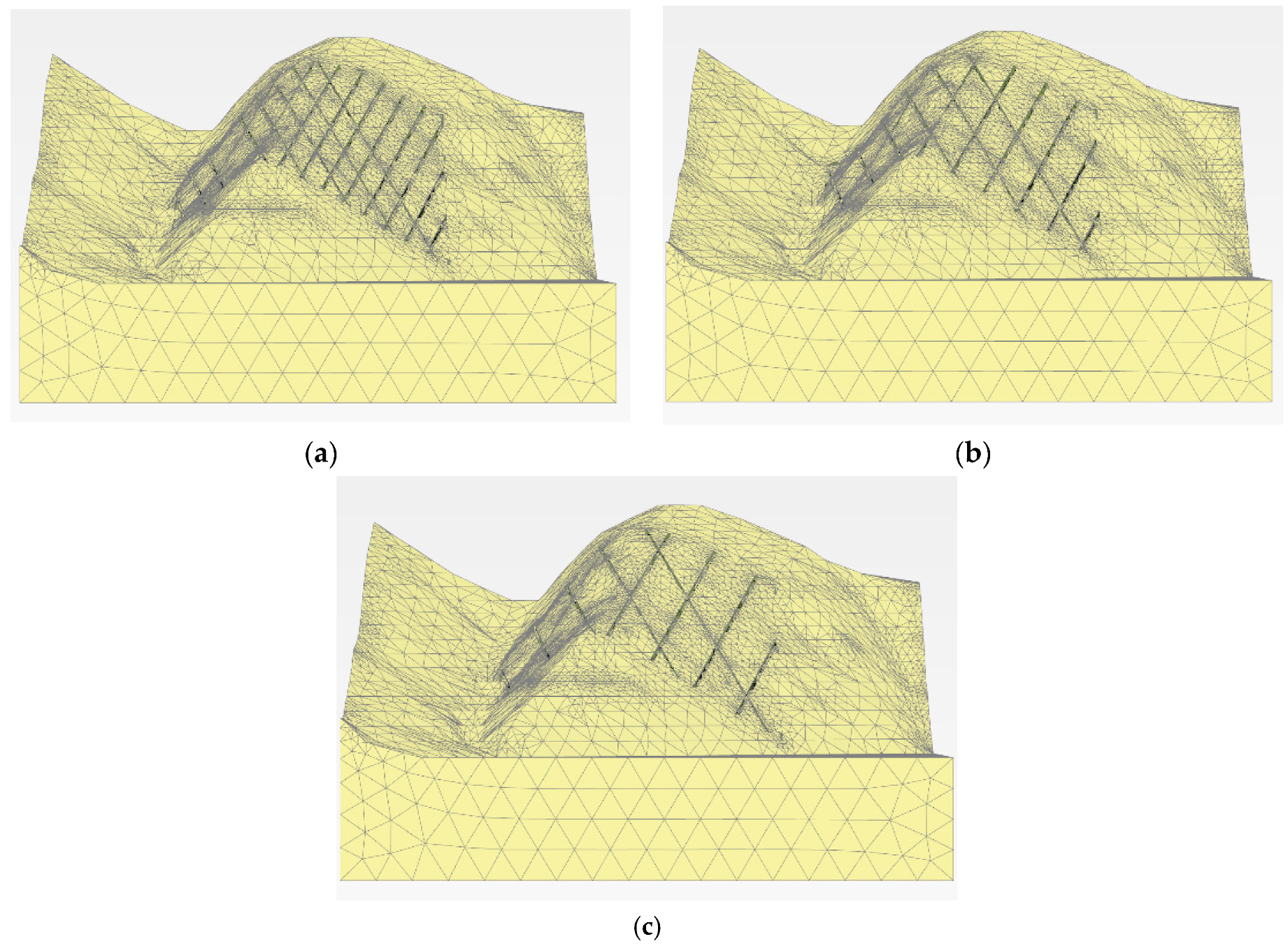
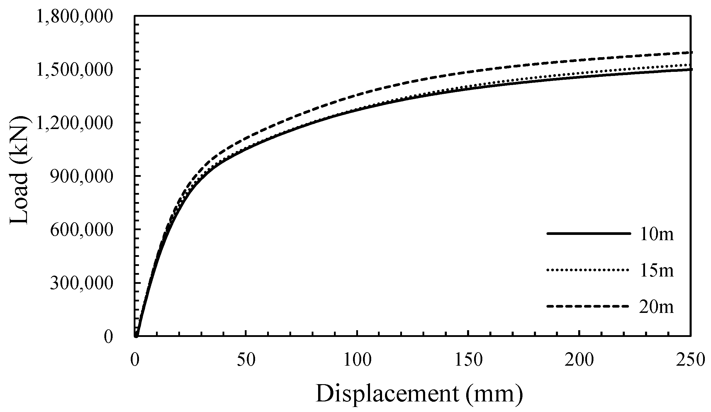
As shown in Figure 11, all three joints in Ulsan Bridge were considered, and the intervals between the joints were set to 10 m, 15 m, and 20 m. Figure 12 shows the load-horizontal displacement curves at different joint spacings.
It can be seen that the ultimate load increases as the joint spacing increases. This is because the number of joints affecting the anchorage became smaller, and the weight of the rock between the joints increased as the interval between the joints increased.

4.3. Effect of Strength Properties on the Joint Surface

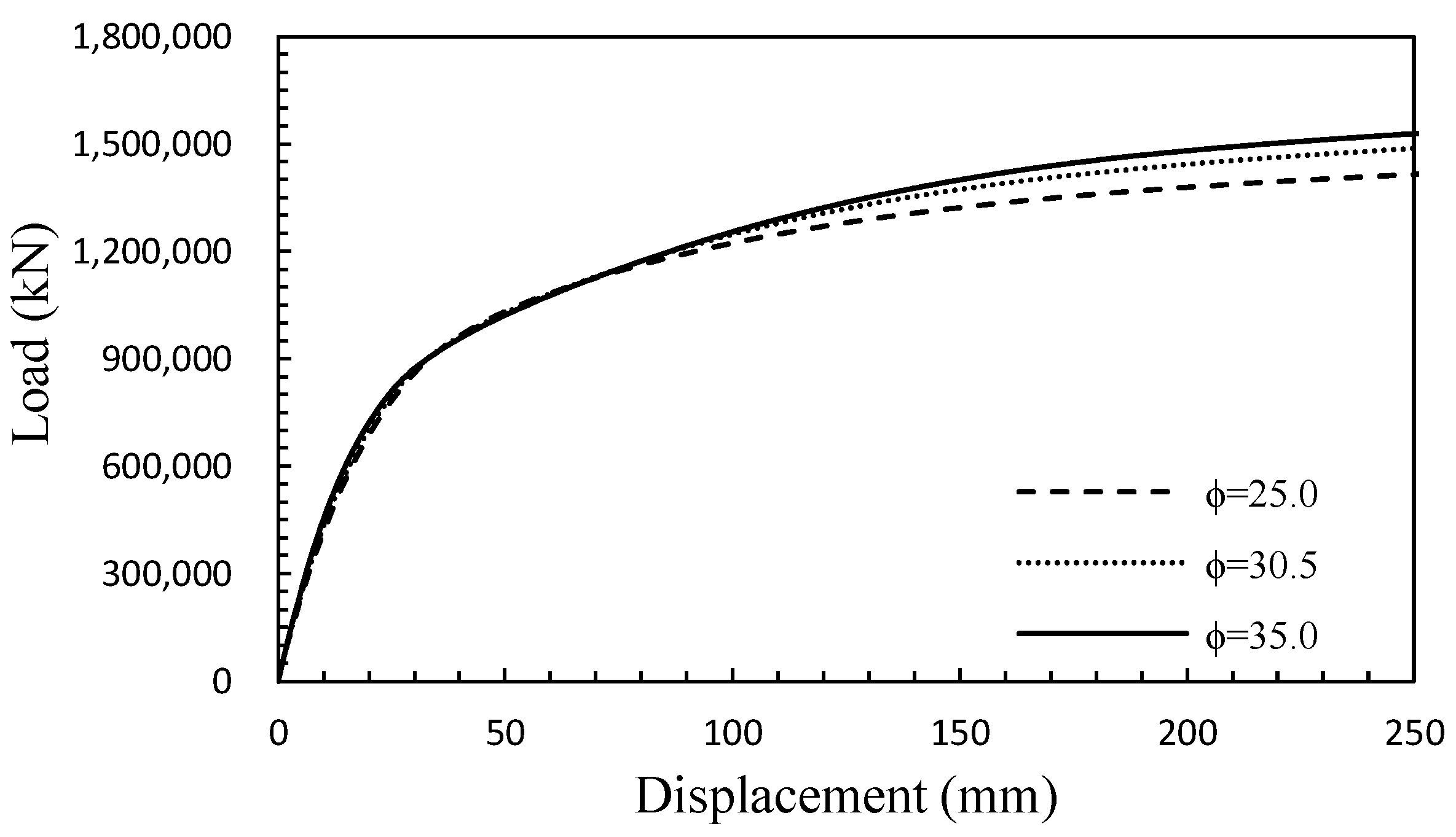
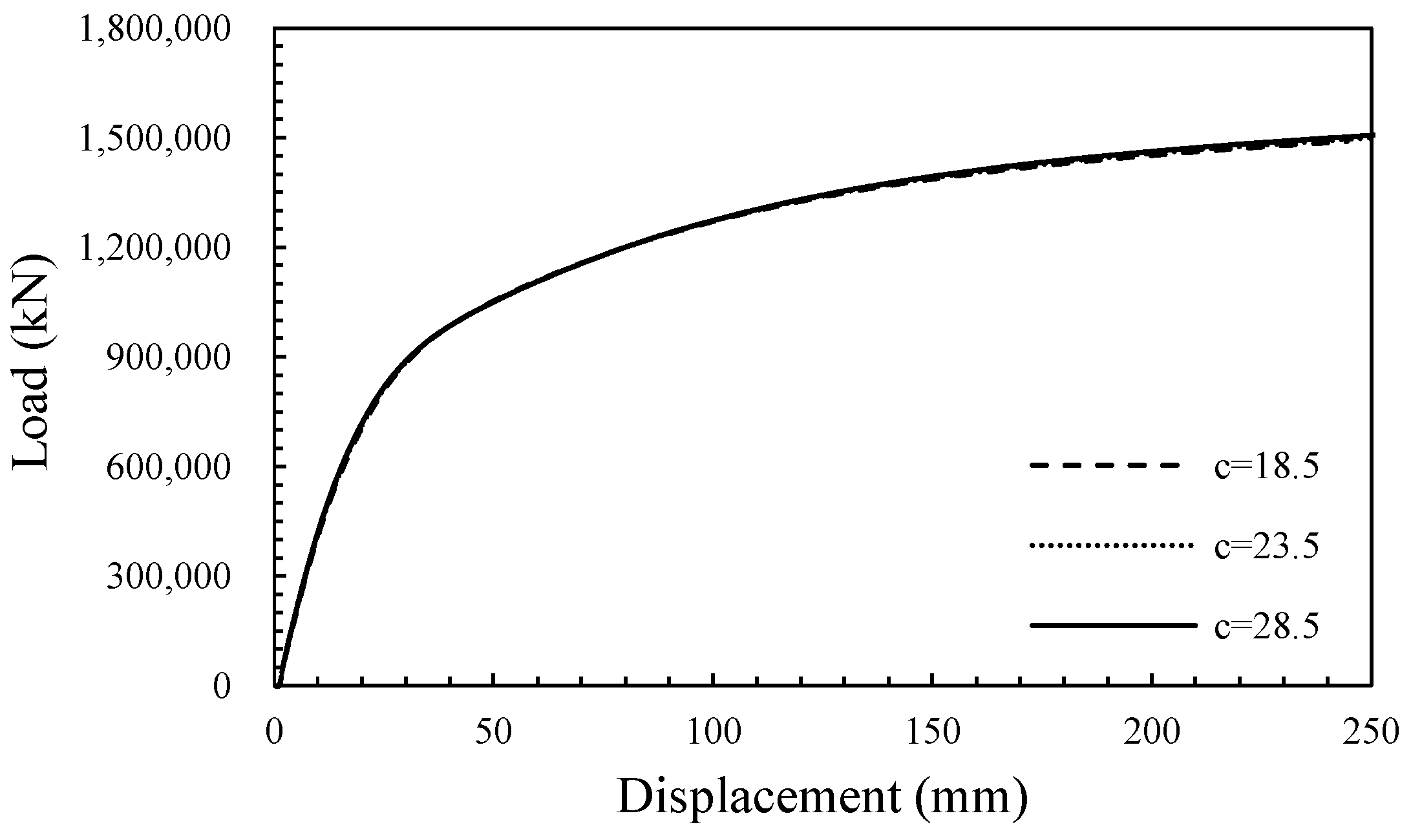
Figure 13 shows the load–horizontal displacement curve based on changes in the internal friction angle of the joint. Figure 14 shows the load-horizontal displacement based on changes in the cohesion of the joint. From Figure 13, it can be seen that the ultimate load of the tunnel-type anchorage increased as the internal friction angle of the joint increased. However, as shown in Figure 14, when the cohesion of the joint increased, the difference in the ultimate load was insignificant. Based on these results, it can be confirmed that as the installation location of the tunnel-type anchorage became deeper, the frictional force due to the weight of the bedrock and the internal friction angle had a dominant influence on the pull-out behavior of the tunnel-type anchorage.

5. Conclusions

The main objective of this study was to numerically investigate the pull-out behavior of a tunnel-type anchorage based on the geometric and rock joint conditions, such as the enlarged part, anchorage spacing, joint orientation, spacing, and the shear strength of the rock joints. The following conclusions can be drawn from the study:
(1)
When there was no enlarged part in the tunnel-type anchorage, the anchorage showed a pull-out failure mode; however, if there was an enlarged part, it showed a wedge-shaped failure mode. Additionally, it was confirmed that the pull-out resistance of the anchorage decreased as the spacing between the anchorages became narrower, similar to the group effect of the pile.
(2)
It was found that the lowest resistance was shown when the tunnel-type anchorage was constructed on the rock with the joints in the direction perpendicular to the cable load. The reason for this could be that the joint direction is similar to the wedge shape, which is a typical failure mode of the tunnel-type anchorage.
(3)
It was found that the ultimate load increased as the joint spacing became wider because the weight of the rock between the joints increased, and the number of joints decreased. In the pull-out behavior of the tunnel-type anchorage, the internal friction angle of the joint was more significant than the cohesion between the joints.

Author Contributions

Conceptualization, M.C.; methodology, M.C., S.S., J.K., and H.L.; software, H.L., and S.S.; formal analysis, M.C.; writing—original draft preparation, H.L.; writing—review and editing, H.L., J.K., and S.S. All authors have read and agreed to the published version of the manuscript.

Funding

This research was supported by a grant (21SCIPB119947-06 and 22SCIP-C151438-04) from the Construction Technology Research Program funded by the Ministry of Land, Infrastructure and Transport of Korean government.

Institutional Review Board Statement

Not applicable.

Informed Consent Statement

Not applicable.

Data Availability Statement

Not applicable.

Conflicts of Interest

The authors declare no conflict of interest.

References

  1. Lekidis, V.; Tsakiri, M.; Makra, K.; Karakostas, C.; Klimis, N. Evaluation of dynamic response and local soil effects of the Evripos cable-stayed bridge using multi-sensor monitoring systems. Eng. Geol. 2005, 79, 43–59. [Google Scholar] [CrossRef]
  2. Gwon, S.G.; Choi, D.H. Static and dynamic analyses of a suspension bridge with three-dimensionally curved main cables using a continuum model. Eng. Struct. 2018, 161, 250–264. [Google Scholar] [CrossRef]
  3. Han, Y.; Liu, X.; Wei, N.; Li, D.; Deng, Z.; Wu, X.; Liu, D. A Comprehensive Review of the Mechanical Behavior of Suspension Bridge Tunnel-Type Anchorage. Adv. Mater. Sci. Eng. 2019, 2019, 3829281. [Google Scholar] [CrossRef] [Green Version]
  4. Deng, Y.; Li, A.; Chen, S.; Feng, D. Serviceability assessment for long-span suspension bridge based on deflection measurements. Struct. Control. Health Monit. 2018, 25, 1–23. [Google Scholar] [CrossRef]
  5. Lim, H.; Seo, S.; Lee, S.; Chung, M. Analysis of the passive earth pressure on a gravity-type anchorage for a suspension bridge. Int. J. Geo-Eng. 2020, 11, 13. [Google Scholar] [CrossRef]
  6. Liu, X.; Han, Y.; Li, D.; Tu, Y.; Deng, Z.; Yu, C.; Wu, X. Anti-pull mechanisms and weak interlayer parameter sensitivity analysis of tunnel-type anchorages in soft rock with underlying weak interlayers. Eng. Geol. 2019, 253, 123–136. [Google Scholar] [CrossRef]
  7. Goremikins, V.; Rocens, K.; Serdjuks, D. Decreasing displacements of prestressed suspension bridge. J. Civ. Eng. Manag. 2012, 18, 858–866. [Google Scholar] [CrossRef]
  8. Sgambi, L.; Gkoumas, K.; Bontempi, F. Genetic algorithms for the dependability assurance in the design of a long-span suspension bridge. Comput. -Aided Civ. Infrastruct. Eng. 2012, 27, 655–675. [Google Scholar] [CrossRef]
  9. Harris, N.K.; Obrien, E.J.; González, A. Reduction of bridge dynamic amplification through adjustment of vehicle suspension damping. J. Sound Vib. 2007, 302, 471–485. [Google Scholar] [CrossRef] [Green Version]
  10. Yi, T.H.; Li, H.N.; Gu, M. Full-scale measurements of dynamic response of suspension bridge subjected to environmental loads using gps technology. Sci. China-Technol. Sci. 2010, 53, 469–479. [Google Scholar] [CrossRef]
  11. Comanducci, G.; Ubertini, F.; Materazzi, A.L. Structural health monitoring of suspension bridges with features affected by changing wind speed. J. Wind. Eng. Ind. Aerodyn. 2015, 141, 12–26. [Google Scholar] [CrossRef]
  12. Xia, Q.; Xia, Y.; Wan, H.P.; Zhang, J.; Ren, W.X. Condition analysis of expansion joints of a long-span suspension bridge through metamodel-based model updating considering thermal effect. Struct. Control. Health Monit. 2020, 27, 1–16. [Google Scholar] [CrossRef]
  13. Jiang, N.; Wang, D.; Feng, J.; Zhang, S.; Huan, L. Bearing mechanism of a tunnel-type anchorage in a railway suspension bridge. J. Mt. Sci. 2021, 18, 2143–2158. [Google Scholar] [CrossRef]
  14. Meyerhof, G.G. Uplift resistance of inclined anchors and piles. In Proceedings of the 8th International Conference on Soil Mechanics and Foundation Engineering, Moscow, Russia, 6–11 August 1973. [Google Scholar]
  15. Das, B.M. A procedure for estimation of uplift capacity of rough piles. Soils Found. 1983, 23, 122–126. [Google Scholar] [CrossRef] [Green Version]
  16. Aydan, Ö.; Ebisu, S.; Komura, S. Pull-out tests of rock anchors and their failure modes. In Assessment and Prevention of Failure Phenomena in Rock Engineering; CRC Press: Istanbul, Turkey, 1993. [Google Scholar]
  17. Shanker, K.; Basudhar, P.K.; Patra, N.R. Uplift capacity of single piles: Predictions and performance. Geotech. Geol. Eng. 2007, 25, 151–161. [Google Scholar] [CrossRef]
  18. Alawneh, A.S.; Malkawi, A.I.H.; Al-Deeky, H. Tension tests on smooth and rough model piles in dry sand. Can. Geotech. J. 1999, 36, 746–753. [Google Scholar] [CrossRef]
  19. Ilamparuthi, K.; Dickin, E.A.; Muthukrisnaiah, K. Experimental investigation of the uplift behaviour of circular plate anchors embedded in sand. Can. Geotech. J. 2002, 39, 648–664. [Google Scholar] [CrossRef]
  20. Lee, N.H.; Moon, I.H.; Ju, I.S. Failure mechanism for large-sized grouted anchor bolt under tensile load. In Proceedings of the 16th International Conference on Structural Mechanics in Reactor Technology, Washington, DC, USA, 12–17 August 2001. [Google Scholar]
  21. Azam, S.; Wilson, G.W.; Herasymuik, G.; Nichol, C.; Barbour, L.S. Hydrogeological behaviour of an unsaturated waste rock pile: A case study at the Golden Sunlight Mine. Bull. Eng. Geol. Environ. 2007, 66, 259–268. [Google Scholar] [CrossRef]
  22. Moayedi, H.; Mosallanezhad, M. Uplift resistance of belled and multi-belled piles in loose sand. Measurement 2017, 109, 346–353. [Google Scholar] [CrossRef]
  23. Albusoda, B.S.; Abbase, H.O. Performance assessment of single and group of helical piles embedded in expansive soil. Int. J. Geo-Eng. 2017, 8, 25. [Google Scholar] [CrossRef] [Green Version]
  24. Seo, S.; Lim, H.; Chung, M. Evaluation of failure mode of tunnel-type anchorage for a suspension bridge via scaled model tests and image processing. Geomech. Eng. 2021, 24, 457–470. [Google Scholar]
  25. PLAXIS. PLAXIS 3D Reference Manual; Bentley: Exton, PA, USA, 2020. [Google Scholar]
  26. Yooshin Co., Ltd. Ulsan Grand Bridge and Access Road Private Proposal Project: Basic Design Report (in Korean); Yooshin Co., Ltd.: Seoul, Korea, 2010. [Google Scholar]
  27. Yooshin Co., Ltd. Ulsan Grand Bridge and Access Road Private Proposal Project: Geotechnical Soil Report (in Korean); Yooshin Co., Ltd.: Seoul, Korea, 2010. [Google Scholar]
Figure 1. Typical types of anchorages: (a) gravity-type and (b) tunnel-type.
Applsci 11 11688 g001
Figure 2. A typical 3D model for FE analysis: (a) design drawings, (b) mountainous area, and (c) anchorage.
Applsci 11 11688 g002
Figure 3. Convergence study for three different mesh densities: load-horizontal displacement curves for tunnel-type anchorages.
Applsci 11 11688 g003
Figure 4. Plane view of an FE mesh for the rock joint: (a) joint set #1, (b) joint set #2, and (c) joint set #3.
Applsci 11 11688 g004
Figure 5. Enlarged height and spacing of the tunnel-type anchorage: (a) enlarged height and (b) spacing.
Applsci 11 11688 g005
Figure 6. Load–horizontal displacement curve with enlarged height.
Applsci 11 11688 g006
Figure 7. Surrounding soil failure mode and angle based on the enlarged height of the tunnel-type anchorage: (a) H = 0 m, (b) H = 2 m, (c) H = 4 m, (d) H = 6 m, and (e) H = 8 m.
Applsci 11 11688 g007
Figure 8. Load-horizontal displacement curve with anchorage spacing.
Applsci 11 11688 g008
Figure 9. Displacement vectors with different tunnel spacing (s): (a) s = 18.5 m, (b) s = 23.5 m, and (c) s = 28.5 m.
Applsci 11 11688 g009
Figure 10. Load-horizontal displacement curve with joint orientation.
Applsci 11 11688 g010
Figure 11. The 3D view of an FE mesh based on joint spacing: (a) 10 m, (b) 15 m, and (c) 20 m.
Applsci 11 11688 g011
Figure 12. Load–horizontal displacement curve with joint spacing.
Applsci 11 11688 g012
Figure 13. Load–horizontal displacement curve with the internal friction angle of joint.
Applsci 11 11688 g013
Figure 14. Load–horizontal displacement curve with joint cohesion.
Applsci 11 11688 g014
Table 1. Soil and rock parameters used for this study [26,27].
Material TypeUnit Weight
(kN/m3)
Elastic Modulus
(kN/m2)
Poisson’s RatioCohesion (kN/m2)Internal Friction Angle (°)
Soil18.020,0000.351030.0
Rock22.01,101,0000.2520033.0
Table 2. Joint parameters for this study [26,27].
Joint Sets AppliedDip/Dip
Direction
Cohesion (kN/m2)Internal Friction Angle (°)Kn
(MPa)
Ks
(MPa)
Joint set #160/16223.530.58.960.78
Joint set #260/34223.530.513.040.87
Joint set #355/25223.530.513.320.89
Table 3. Summary of the numerical analyses conducted.
ParametersCases
Enlarged part (m)0, 2, 4, 6, and 8
Anchorage spacing (m)18.5(1.7D), 23.5(2.2D), and 28.5(2.6D)
Joint dip/dip direction60/162, 60/342, and 55/252
Joint spacing (m)s: 10, 15, and 20
Cohesion for rock joint (kPa)c: 18.5, 23.5, and 33.5
Internal friction angle for rock joint (°)ϕ: 25, 30.5, and 35
D: the diameter of the tunnel-type anchorage.
Publisher’s Note: MDPI stays neutral with regard to jurisdictional claims in published maps and institutional affiliations.