Article

Robust Control for Non-Minimum Phase Systems with Actuator Faults: Application to Aircraft Longitudinal Flight Control

by
Aisha Sir Elkhatem
1,2,*,
Seref Naci Engin
2,*,
Amjad Ali Pasha
3,*,
Mustafa Mutiur Rahman
4 and
Subramania Nadaraja Pillai
5
1
Aeronautical Engineering Department, Sudan University of Science and Technology (SUSTECH), Khartoum 11111, Sudan
2
Control and Automation Engineering Department, Yildiz Technical University, Istanbul 3420, Turkey
3
Aerospace Engineering Department, King Abdulaziz University, Jeddah 21589, Saudi Arabia
4
Department of Mechanical and Mechatronics Engineering, University of Waterloo, Waterloo, ON N2L 3G1, Canada
5
Turbulence & Flow Control Lab, School of Mechanical Engineering, SASTRA Deemed University, Thanjavur 613401, Tamil Nadu, India
*
Authors to whom correspondence should be addressed.
Appl. Sci. 2021, 11(24), 11705; https://doi.org/10.3390/app112411705
Submission received: 30 October 2021 / Revised: 6 December 2021 / Accepted: 7 December 2021 / Published: 9 December 2021
(This article belongs to the Special Issue Dynamic Phenomena)

Abstract

:
This study is concerned with developing a robust tracking control system that merges the optimal control theory with fractional-order-based control and the heuristic optimization algorithms into a single framework for the non-minimum phase pitch angle dynamics of Boeing 747 aircraft. The main control objective is to deal with the non-minimum phase nature of the aircraft pitching-up action, which is used to increase the altitude. The fractional-order integral controller (FIC) is implemented in the control loop as a pre-compensator to compensate for the non-minimum phase effect. Then, the linear quadratic regulator (LQR) is introduced as an optimal feedback controller to this augmented model ensuring the minimum phase to create an efficient, robust, and stable closed-loop control system. The control problem is formulated in a single objective optimization framework and solved for an optimal feedback gain together with pre-compensator parameters according to an error index and heuristic optimization constraints. The fractional-order integral pre-compensator is replaced by a fractional-order derivative pre-compensator in the proposed structure for comparison in terms of handling the non-minimum phase limitations, the magnitude of gain, phase-margin, and time-response specifications. To further verify the effectiveness of the proposed approach, the LQR-FIC controller is compared with the pole placement controller as a full-state feedback controller that has been successfully applied to control aircraft dynamics in terms of time and frequency domains. The performance, robustness, and internal stability characteristics of the proposed control strategy are validated by simulation studies carried out for flight conditions of fault-free, 50%, and 80% losses of actuator effectiveness.

1. Introduction

The worldwide statistical summary of Boeing and Airbus commercial aircrafts during 1958–2020 confirms that loss of flight control in flight (LOC-I) has the largest share of the causes of catastrophic accidents [1,2,3]. This motivates researchers to develop effective control systems more in aviation-related studies due to the highly nonlinear nature of the aircraft dynamics and being more prone to perturbation and disturbances, which are also among the obstacles that arise when designing robust flight control systems [4]. In this context, it is well known that non-minimum phase (NMP) dynamics are characterized by the right half plane (RHP) zeros that yield undesirable behavior, such as moving in the opposite direction first before correcting its direction. Besides, the non-minimum phase nature of dynamics causes physical limitations to the open-loop bandwidth, and thus restricting the benefits of the feedback control system [5]. This can be seen in the tracking control problem, where the feedback controller can track the reference signal perfectly, but the system states can become unstable, which is referred to as the internal stability problem generated by non-minimum phase dynamics [6].
Various methodologies have been proposed to control plants with non-minimum phase characteristics. The main features of these approaches from the transformation of NMP nonlinear systems to approximately minimum phase systems such as approximate feedback linearization (FBL) [7], real-zero elimination [8], and stable inversion [9] approaches, to other approaches that investigate the possibility of overcoming unstable internal dynamics by introducing a dummy output thereby obtaining the desired trajectories via methods such as the output redefinition method [10]. More recent works are rather destined to the inversion-based nonlinear controllers to deal with nonlinear non-minimum phase systems [11,12].
Although previously proposed approaches in literature showed a strong capability for dealing with NMP dynamics, there still are some inadequacies that make them restricted to certain applications and cases. Among those reported methods, for instance, the approximate feedback linearization method can be classified into two approaches: input-output FBL and input-state FBL. While the input-output FBL cannot cope with NMP dynamics satisfactorily, the input-state FBL can achieve a good asymptotic closed-loop stability. However, in this case, the states of the system must be known precisely [13]. Furthermore, the input-state FBL method suffers from the robustness problem in the existence of system uncertainties [14]. On the other hand, inversion-based and stable inversion approaches are completely dependent on accurately determined system models and they are susceptible to the closed-loop system instability problem in the case of perturbation of external disturbances [15,16]. Finally, the pole-zero cancellation-based approaches such as the real-zero elimination approach led to creating a non-causal controller and hence internally unstable systems [17,18].
These limitations are the impetus for the proposed method, which can ensure the internal stability, robustness, and a desirable performance in dealing with NMP dynamics by means of transforming the NMP to minimum-phase dynamics using the fractional-order control for the first time then using the existing powerful linear control techniques such as the proportional–integral–derivative (PID) controller, H 2 , H , and linear quadratic regulator (LQR) optimal control. Therefore, the main advantage of the proposed approach is the reliance on the classical feedback control to obtain a robust and high performance as well as internal stability against NMP dynamics. It can be concluded that the main differences between the proposed approach and the existed methods in literature that essentially rely on transforming the non-minimum phase to minimum phase dynamics are:
1.
Compared with the input state FBL method, which is based on adding hard constraints such as the second-order Lyapunov constraint to ensure the closed-loop stability in the case of NMP dynamics [19], the proposed method ensures a robust and stable closed-loop for the NMP dynamics with actuator faults without any additional constraints.
2.
In contrast with the real-zero elimination, which can be applied only with MIMO systems [10], the proposed method is appropriate for both MIMO and SISO systems without necessitating to reach all the internal states.
Generally, the linear quadratic regulator (LQR), which is based on the optimal control theory, offers more significant advantages than the classical control methods with respect to time response performance, control effort, robustness for uncertainty, and disturbance and noise rejection capabilities [20,21]. As reported in the literature, the LQR controller has been successfully applied to deal with various types of NMP dynamics, for instance, m-link robotic manipulators [22], phase electrohydraulic systems (EHS) [23], and wheeled bipedal robot with kinematic loops [24]. It is remarkable that the first significant application of multivariable control based on the linear quadratic regulator (LQR) started in the Boeing company (Chicago, IL, USA) in 1978 as a part of NASA’s research programs [25]. In their work, the LQR theory was applied as a second option for repeated attempts based on classical synthesis techniques to improve the control of heading- and track-hold functions of autopilot developed for the Boeing 767 commercial transport airplane. Furthermore, the LQR and linear quadratic gaussian (LQG) design approaches have been implemented for more than 20 years in the autopilots of Boeing aircraft [26]. As an example, the work in [27] focused on the design of a high-performance control of longitudinal dynamics of a highly flexible aircraft (HFA), where integral reinforcement learning (IRL) and LQR were combined to constitute an adaptive online data-driven tracking controller. The data were collected within an expected time interval using the IRL technique, and then the LQR utilized these data to calculate the optimal feedback gains.
The LQR has been introduced with other control strategies to manage the aircraft’s non-minimum phase nature. In [28], a quantitative feedback theory (QFT) was proposed and compared with the LQR control approach to solve the non-minimum phase problem of the longitudinal model of hypersonic aircraft and hence a robust controller was designed against the uncertainty problem of large aerodynamic parameters due to complex flight environments. In another noteworthy work, a new methodology based on decomposing the non-minimum phase aircraft model into a minimum phase part and a non-minimum phase part for output tracking of a vertical take-off and landing (VTOL) aircraft was introduced [29]. Then, an inversion controller was used for the minimum phase part, while an LQR controller for a new simpler non-minimum phase part was applied to accomplish output tracking with stability. Another control approach that appeared in [30] is based on converting the aircraft’s longitudinal dynamics from a non-minimum phase to a minimum phase system by redefining the system using acceleration at the instantaneous center-of-rotation (ICR) and then applying the dynamic inversion approach to the converted acceleration dynamics. In the notable works of [31,32], a different approach to the NMP problem was proposed, which involved designing a feedback control system based on exact and approximate output tracking of aircraft dynamics instead of input–output linearization of the models describing the aircraft dynamics. The LQR controller was also augmented with integrators to obtain zero steady-state error to a particular input [33,34] and hence converted the regulation problem to the tracking problem.
Over the last decade, fractional-order-based control, which consists of non-integer order derivatives and integrals, is one of the research areas that has gained attention due to the continuous demand to obtain precise controllers for plants with complex dynamics [35]. Most of the proposed fractional-based controllers [36] showed better performance than the integer-based controller when applied to the systems represented with fractional-order or non-fractional-order dynamics. On the other hand, some researchers opted for designing robust flight control systems based on the fractional-order approach for classical and optimal controllers, specifically for UAVs. In [37], for example, the actuator fault and external disturbances were successfully compensated online by applying an adaptive and fractional-order sliding mode control (FOSMC) method to a UAV model.
In general terms, the fault-tolerant control (FTC) approach is the most important civil aircraft requirement to guarantee an acceptable performance, reliability, and stability when actuator malfunctions occur [38,39,40,41,42]. One of the two main types of FTC systems is passive FTC (PFTC) [43,44], which relies on robustness properties of the controller to compensate for some known faults and maintain the stability of the system without fault detection and diagnosis (FDD) and controller reconfiguration (CR) units. The second type, an active fault-tolerant control system (AFTC) studied in [45,46,47], requires a fault detection and diagnosis (FDD) unit to provide information about the magnitude and location of the current fault [48]. Then, it reconfigures the controller to maintain the total stability of the system. Some research groups [49,50], on the other hand, introduced the adaptive-FTC techniques that can accommodate faults without fault detection and isolation (FDI) units.
The main contribution of this paper is to develop a new control structure to overcome the performance and robustness limitations of the classical feedback control system when dealing with non-minimum phase dynamics, especially for some fault cases. The focal idea is based on converting non-minimum phase pitch angle dynamics into an approximate minimum phase system. The proposed approach combines the fractional-order integral controller as the feedforward controller to deal with the non-minimum phase nature of aircraft dynamics with the optimal feedback controller to achieve a good closed-loop system performance and stability of the new augmented minimum phase dynamics. The parameters of the proposed controller are calculated by formulating the control problem as a single-objective optimization problem and solving it by a heuristic global optimization technique according to a fitness function. One of the objectives of this study is to evaluate the capability of the proposed structure to handle 50% and 80% losses of actuator effectiveness.
The main differences between the proposed control structure and the combination of the optimal control theory with fractional control presented in the literature [51,52] can be listed as follows:
1.
In the proposed approach, the fractional-order integral controller (FIC) is augmented with an LQR as a pre-compensator to cope with the non-minimum phase problem.
2.
The implementation of non-integer order derivatives and integrals in the closed-loop to function as a pre-compensator extends the LQR optimal problem from optimizing just the states of the system to optimizing the new augmented dynamics, whereas, in the literature, for example, the integrator is added to the LQR controller loop as an error tracker.
3.
The proposed controller exhibits superior performance even in fault cases that are considered one of the challenges in practical applications.
4.
The fractional-order integral control (FIC) is compared with a fractional-order derivative control (FDC) in terms of internal stability and closed-loop stability.
5.
The feedback controller and the pre-compensator, i.e., feedforward controller parameters are calculated simultaneously to create a more flexible and robust control system.
The article is organized as follows. Section 2 introduces the problem description and dynamics of the aircraft of interest. Then, the methodology with the underlying theoretical explanations is described in Section 3. Following this section for preliminaries, the proposed adaptive linear quadratic regulator fractional integral (A-LQR-FI) control structure is presented in detail in Section 4. The performance of the proposed approach is also compared with the pole placement controller, which is one of the commonly used methods in aircraft control. The results are discussed with plots and tables comparatively. The ultimate remarks derived from this comprehensive work are given in the final section, namely, conclusions.

2. Problem Description, the Proposed Approach, and Aircraft Dynamics

In this section, the problem of aircraft dynamics augmented adversely with non-minimum phase effects and actuator faults is addressed and the proposed control scheme as an attempt for a solution is presented in detail.

2.1. Non-Minimum Phase Problem

The aircraft of interest in this paper is the Boeing 747 100/200 series, flying at the altitude of 4000 m with 0.567 Mach number corresponding to 185 m/s speed [53]. Non-minimum phase behavior is typically encountered when pitching up an aircraft to increase its altitude. When the elevator is deflected up, a downward force is produced on the tail that pushes it down relative to the center of gravity. Then, the aircraft angle of attack (AOA) is increased due to the lift on the main wing causing the aircraft to climb (pitches upward). However, before the altitude increases, the aircraft goes down initially (undershoot) due to the reduced net lift in the center of mass. A typical step response of such a system is presented in Figure 1. The conventional control laws, such as optimal controllers and classical controllers, cannot work effectively if they are directly applied to the non-minimum phase systems or if the dynamics involve faults due to unstable zeros and internal stability problems. Therefore, designing an effective control system with a standard LQR technique is a challenging issue due to the limitations created by the closed-loop bandwidth, which is narrowed due to the non-minimum phase dynamics.

2.2. Proposed Solution

In this work, the idea is to transform the non-minimum phase aircraft longitudinal dynamics into minimum phase by inserting a fractional-order integral controller (FIC) as a pre-compensator. Further, the design and implementation of an optimal LQR controller to control the whole augmented dynamics as shown in Figure 2 is introduced. Furthermore, the adaptiveness of this control system structure is achieved by simultaneously optimizing the Q and R weighting matrices with the pre-compensator parameters of K I and λ assigned by the particular swarm optimization (PSO) algorithm according to an IAE performance index.
This nested structure comprising the LQR, and the FIC controller is presented in Figure 2. The optimal LQR controller is employed to obtain a closed-loop optimal control law for the augmented system that ensures the state variables converge to zero in a limited time, minimizes the control efforts, and compensates for the actuator faults and external disturbances. On the other hand, a fractional-order pre-compensator, i.e., FIC is added to the control loop to resolve the problems that can be confronted due to the non-minimum phase characteristics. The pre-compensator directly generates control commands for the actuator to deal with the longitudinal aircraft dynamics.
Here, the problem is considered as the online single-objective optimization problem exploiting a PSO optimization algorithm. The control design variables of the optimization problem are chosen as weighting matrices (Q and R), and adaptive fractional-order integral pre-compensator parameters ( K I , λ ) to track the desired pitch angle under the conditions of normal flight and actuator losses of effectiveness by minimizing the performance index of IAE. The general form of the online optimization problem is formulated based on the constraints of the design variables vector, as explained in Section 4.2.

2.3. Aircraft Dynamics

The longitudinal state-space dynamics of the Boeing 747-100/200 model obtained through Jacobian linearization at the trim point as reported in [53] can be expressed in state-space form as,
x ˙ t = A x t + B u t ,   y t = C x t + D u t
Here, A     R n × n ,   B     R n × m ,   C     R p × n are the system, input, and output matrices, respectively, x t     R n × 1 is the state vector, u t     R   m × 1 is the input or control vector, and y t     R p × 1 is the output vector. The longitudinal state vector, control vector, and output vector can be defined as x = α   q   V T A S   θ   h e T , u = δ a   δ e T , and y = γ   a   θ   q   V   h e T where the five states are the angle of attack α (rad), pitch rate q (rad/s), the true velocity V T A S (m/s), pitch angle θ (rad), and altitude h e (m). There are two control inputs, the stabilizer deflection δ a   rad and elevator deflection   δ e (rad). The measurements available are flight path angle γ (rad), aircraft acceleration   V ˙   m / s 2 , pitch angle θ   (rad), pitch rate q (rad/s), velocity V (m/s), and altitude h e (m).

3. Preliminaries

This section introduces the definition of fractional-order control, its role in the control loop, and approximation methods in the implementation stage. Finally, a brief description of the particle swarm optimization algorithm is presented.

3.1. Fractional-Order Integral Definition

The fractional-order integral is defined by Riemann-Liouville based on a natural consequence of Cauchy’s formula for repeated integrals [54], which reduces the computation of the primitive corresponding to the n-fold integral of a function f t to a simple convolution equation as follows,
D n f t = 1 Γ n 0 t f y t y n 1 d y
which corresponds to the Riemann-Liouville’s definition for the fractional-order integral of order n     R + . Here, n is a general non-integer number and gamma function, and Γ is used to extend the factorial to the operation of non-integer numbers, i.e., Γ x = x 1 ! , whether or not x is a whole number.

3.2. Fractional-Order Approximation

Even though the high robustness and excellent design flexibility properties of non-integer, i.e., fractional-order controllers [55], there is no direct realization of non-integer differentiators and integrators of these controllers due to the requirement of the theoretically infinite size of memory. Implementation of a non-integer controller needs an efficient approximation. The Oustaloup method [55] is one of the methods used to approximate the non-integer differentiators and the integrators by employing a finite-dimensional rational filter according to the equation:
s γ k k = 1 N s + ω k s + ω k
The poles and zeros of a rational filter are recursively distributed in the frequency range [ ω b ,   ω h ]. Then, the equation of the Oustaloup filter can be written as,
s γ = k k = 1 N s + ω k s + ω k
where the poles, zeros, and gains are evaluated as,
ω k = ω b ω u 2 k 1 γ N ω k = ω b ω u 2 k 1 + γ N k = ω h γ
Here, ω u = ω h ω b   and N is odd or even integer and is the order of the filter,   γ   is the order of derivative and,   ω b ,   ω h are the lower cut-off and upper cut-off frequencies, respectively.
The approximated fractional-order integral and derivative for all λ and μ values between 0.1 to 0.9 by the standard Oustaloup method can be obtained using MATLAB functions. According to the approximation results for λ and μ equal to 0.1 as an example in Appendix A, the pole and zero locations are placed at a far location to the origin in the left half-plane (LHP), which can improve the internal stability in the presence of the non-minimum phase dynamics. In this work, the λ and μ variables are chosen as one of the design vectors that can be selected adaptively using the PSO algorithm. Moreover, to ensure that the pre-compensator work in the fractional range (i.e., λ and μ will not have an integer value), the upper and lower values of λ and μ are chosen less than one within the region of 0.1 to 0.9.

3.3. Particle Swarm Optimization Algorithm (PSO)

Particle swarm optimization, PSO, is an intelligent optimization algorithm, which belongs to a class of optimization algorithms called metaheuristic-PSO. PSO is based on the paradigm of swarm intelligence, and it is inspired by the social behaviors of animals such as fish and birds. It is a simple but powerful optimization algorithm and is successfully used in numerous engineering applications such as modelling, signal processing, and robotics along with machine learning, data processing, and many other techniques [56,57,58].

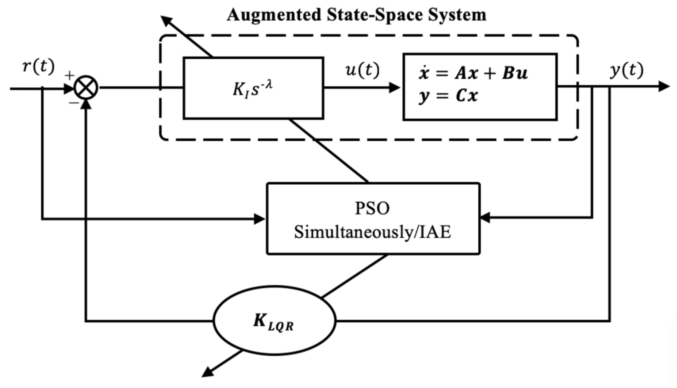
4. Proposed Adaptive Linear Quadratic Regulator with Fractional Integral (LQR-FI) Control Structure

The proposed adaptive linear quadratic regulator augmented with fractional integral (LQR-FI) control structure is introduced with its preliminaries in the state–space representation.

4.1. Augmented State-Space Model

According to the proposed control loop structure, as shown in Figure 2, the LQR controller optimizes the states of the augmented system, which contains the states of the original system and the states of the fractional-order pre-compensator. The proposed augmented system can be expressed in state-space form as,
z ˙ t = A n e w z t + B n e w u t y t = C n e w z t + D u t
The A n e w , B n e w and C n e w are the augmented matrices and obtained as
z ˙ t = x ˙ t e ˙ t ,   A n e w = A A 0 A ,   B n e w = B B ,   C n e w = C   C
x ˙ t e ˙ t = A A 0 A x t e t + B B u t y t = C   C   x e + D u t
Here, A , A , B , and C are non-zero matrices, and e t are the states that are added by the pre-compensator. We can see that the obtained new matrices,   A n e w , B n e w , C n e w contain a non-zero effect on the states and output of the pre-compensator. The objective of the LQR is to find a state feedback control law for the augmented system as in the equation as follows:
u t = K l q r z t
which minimizes the quadratic performance cost function
J = 0 z Q n e w z +   u Ru d t
Here, K l q r = R 1 B n e w T P can be obtained by solving the algebraic Riccati equation (ARE) for the system.
P A n e w + A n e w T P + Q P B n e w R 1 B n e w T P = 0
Here, Q n e w is the augmented system state weighted matrix, which is calculated simultaneously with R, λ , and K I by the PSO algorithm. PSO algorithm adaptively changes the gains of the proposed controller according to the designed constrain parameter vectors. Then, the cost function maintains the stability of the controlled system and obtains zero tracking error.

4.2. Mathematical Model and Constraints of the Proposed Controller Based on PSO Optimization

As stated, in this paper, the control objective is simply to overcome the non-minimum phase behavior problems when the aircraft is pitching up. Therefore, a successful controller is designed based on optimal control theory in the case of actuator losses of effectiveness faults. A fractional-order integrator is used as the compensator to convert the system from a non-minimum phase to a minimum phase, and then the linear quadratic regulator is applied for the resultant minimum phase dynamics to obtain a closed-loop optimal control law. The LQR performance matrices Q n e w ,   R and the fractional integrator parameters, λ , K I are chosen as design parameter vectors, which can be determined by minimizing the objective function, which represents the errors between the required and the actual pitch angle utilizing PSO. The objective function is selected as an integral of the absolute magnitude of the error (IAE) performance index. The comparison between the fractional-order integrator and fractional-order derivative is obtained similarly by considering the fractional-order derivative instead of the fractional integral in the proposed structure as presented in Figure 2.
The optimization problem is formulated mathematically as follows.
Objective   function   = minimize I A E = 0 T e t d t
Here, e t = r t y t is subjected to:
constraints = Q n e w l o w e r < Q n e w < Q n e w u p p e r R   l o w e r < R   < R   u p p e r K I m i n < K I < K I m a x λ m i n < λ < λ m a x
The lower and upper bound for the design variables are set as follows. First, LQR performance matrices, Q n e w and R ,
Q n e w , l o w e r = diag 0.01 , 0.01 ,   0.01 ,   10 , 0.01 , 0   0 , Q n e w , u p p e r = diag 100 ,   100 ,   100 ,   1000 ,   100 ,   0 0
The Q n e w is selected in this way so that approximately 100 times as much effort is put to keep the state of pitch angle small. As known, large R means more control effort.
R l o w e r = diag 10 , 10 ,   R l o w e r = diag 100 , 100
Second, fractional-order integral parameters, K I and λ ,
upper   and   lower   band = 150 < K I < 150 0.1 < λ < 0.9 0.1 < μ < 0.9  
In general, R and Q n e w matrices are known as the LQR controller performance matrices, which can be used as design parameter vectors to penalize the dynamic state variables and the control signals. In the case that is under consideration , Q n e w is penalizing the aircraft and pre-compensator states, whereas R is penalizing the elevator control signal. Still, the target is to penalize the state variables of aircraft, which represent pitch rate, true airspeed, angle-of-attack, pitch angle, and altitude. Nevertheless, the changes occurring in the fractional-order integrator states are not of concern. For this reason, the fractional-order integrator states are selected as equal to zeros in the Q n e w   matrix, which means more attention is paid to keeping all aircraft states near zero as much as possible compared with the states of the fractional integrator compensator. Since the fractional-order integration parameters are simultaneously optimized with the state-feedback gain vector of K l q r , it can ensure a good traceability performance while keeping all states near zero. Moreover, it can improve the convergence of the optimization algorithm to an optimal solution.
The critical issue related to the online optimization process is the dependability of the closed-loop stability behavior on the appropriate selection of the control design parameters over evolutionary time, i.e., the convergence of the PSO algorithm to an appropriate selection of control design parameters. This holds true because the closed-loop system may be unstable for the consecutive time intervals of evolution in the case of inappropriate selection of control design parameters. Hence, in this paper, the selection of an ideal control design parameters vector to the next time PSO evolution interval is based on the instant positions of the poles on the s -plane for the closed-loop system. As known, the system is stable if the closed-loop poles lie on the left half of the complex plane. The best parameter selection during the optimization process is achieved by adding more constraints to force the PSO algorithm to converge into the global minimum to obtain the optimal controller parameters. We can summarize the idea as follows:
(1)
Calculate the real value of eigenvalue of the closed-loop system according to the equation,
A n e w   c l = A n e w B n e w K l q r
(2)
Then, according to the obtained eigenvalues in step one, the PSO particles are updated along with position and velocity values with or without constraints as follows: if the position of the pole n stays on the right half of the s -plane, the objective function, IAE, is allocated to 10 3 to force the algorithm to find a better solution in the next election. If not, the obtained IAE value is carried out for the next selection.
Moreover, the proposed controller is examined for actuator faults. The type of faults that are considered in this paper is the loss of effectiveness, which are an attenuation in the actuator efficiency or gains due to lack of hydraulic fluids or lubrication [39]. System actuator faults can be compensated by means of solving the optimization problem presented in Equations (11)–(14). Then, in the case of fault, the input to be optimized,
U f = α × u
where, U f   is the faulty input, u is the nominal control, and α = diag α 1 , α 2 , α 3 , . α m . Here, the attenuation factor changes within the range of 0 (full fault) to 1 (no-fault).

5. Results and Discussions

The results of theoretical analyses and simulation studies are presented with tables and time response plots to evaluate the performance of the proposed control strategies involving LQR, PSO, and fractional-order controllers implemented to cope with the adverse dynamics of the pitch maneuvers under various fault conditions, namely, various degrees of losses in the actuator effectiveness due to hydraulic fluid leakages or insufficient lubrication. As a further comparison, the pole placement controller is applied under the same conditions. The results produced by the components of the proposed control strategy and that of others are presented under individual subsections to exhibit the achievements.

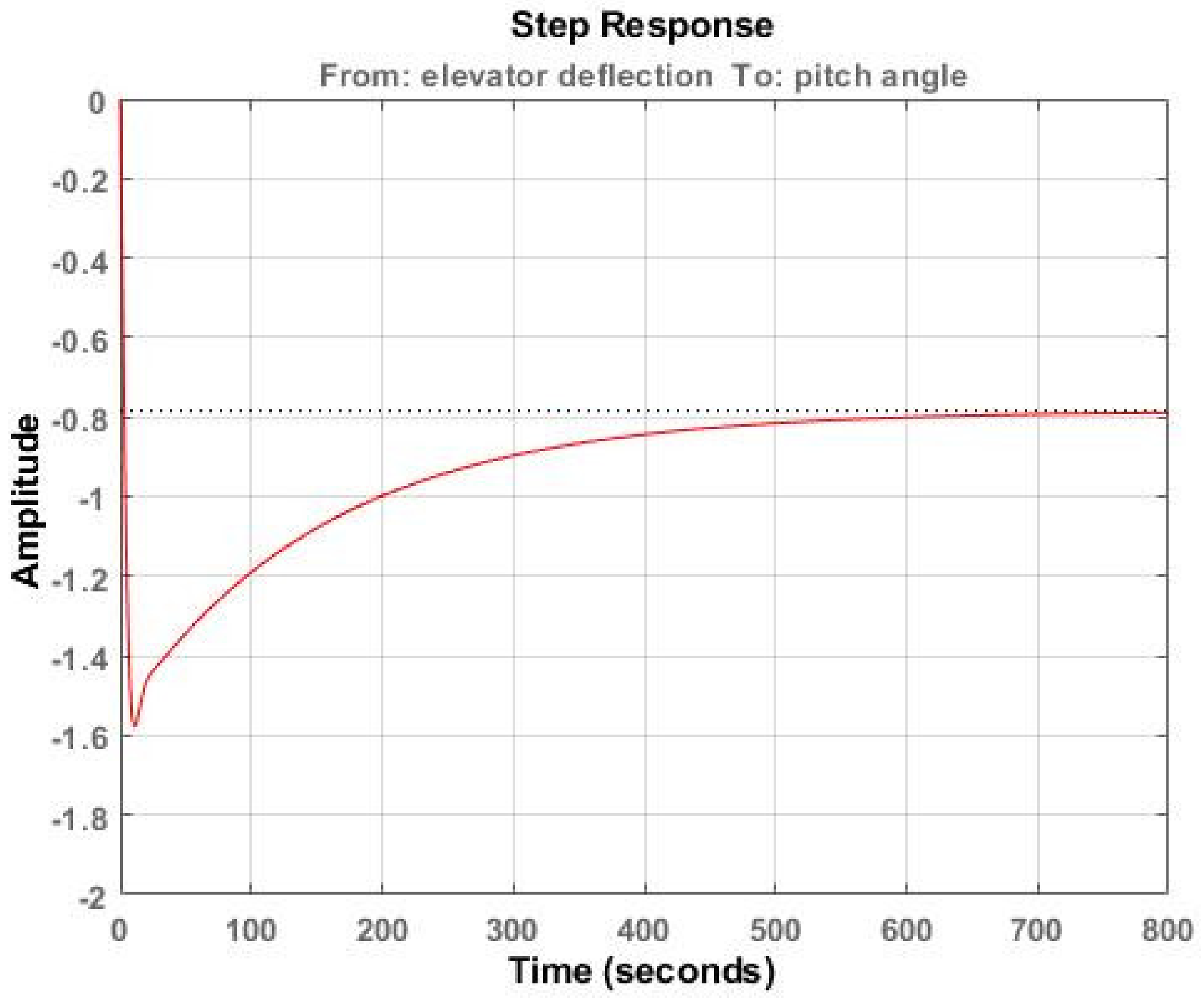
5.1. Open-Loop Step Response: Augmented Dynamics

As a first step, to verify the effectiveness of the proposed pre-compensator for solving problems related to the non-minimum phase behavior of aircraft pitching up, the augmented dynamics of the open-loop system that produced the step responses with the proposed λ values of 0.1 to 0.9 of fractional integral and with the effects of the integral gain, K I are examined without the impact of the LQR controller. As seen in Figure 3a, the non-minimum phase effects of the aircraft pitch angle dynamics on the step response previously presented in Figure 1, are entirely compensated through all proposed values of λ .
Likewise, the step responses of the augmented dynamics in the case of a fractional-order derivative pre-compensator are presented in Figure 3b. The plots show that the augmented dynamics are still in the form of non-minimum phase dynamics, exhibiting initial undershoots. As a result, it can be concluded that the fractional-order derivative pre-compensator cannot convert the non-minimum phase dynamics to the minimum phase because of the high gains that are multiplied for a finite-dimensional rational filter when a fractional-order derivative is approximated for all μ values as presented in Appendix A, which drive the system to move in the wrong direction initially.

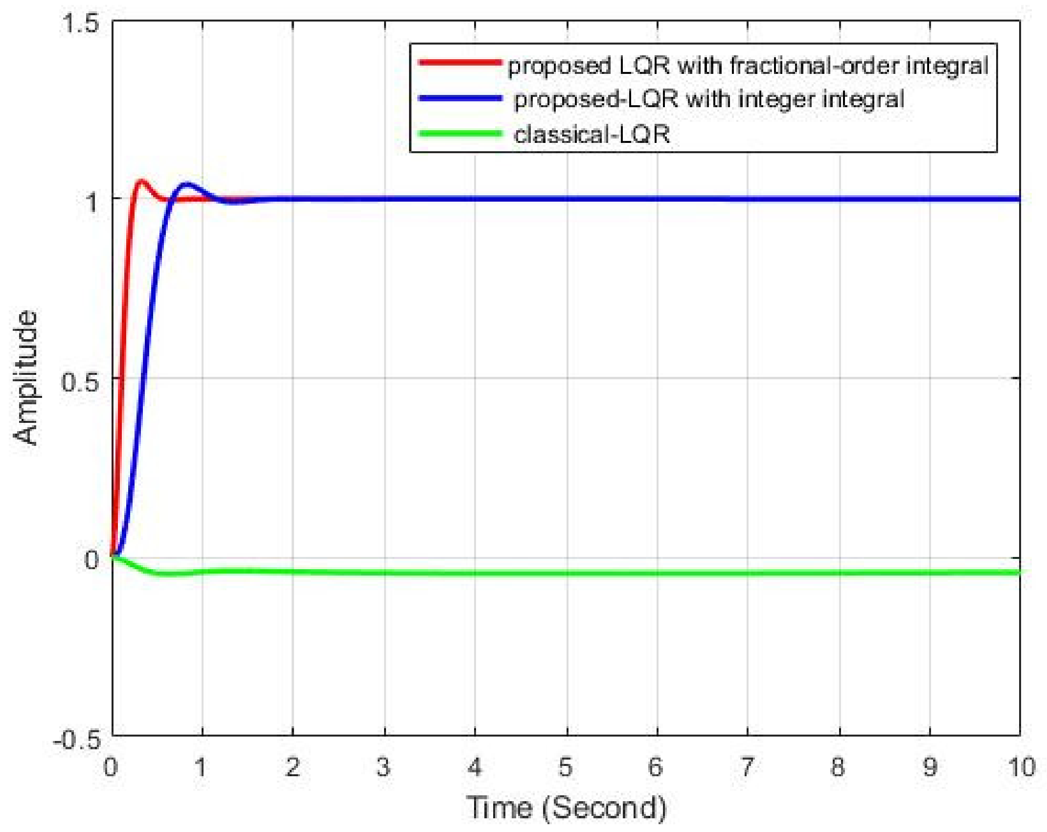
5.2. Closed-Loop Step Response: Proposed LQR-FIC Controller

The proposed optimal LQR controller with fractional-order integral compensator, LQR-FIC is evaluated based on an online optimization problem explained in Section 4.2 for normal flight conditions and with the faults of 50% and 80% actuator losses of effectiveness as presented in the block diagram of the proposed controller. The design parameters denoted as   λ , K I , Q n e w and R simultaneously satisfy the current IAE performance index value.
The LQR controller with an adaptive integer-order integral compensator K I s 1 is also considered and its performance is compared with that of the fractional-order integral compensator to evaluate the effectiveness of changing the λ value on maintaining the augmented state–space dynamics internally stable. The performance of the proposed controllers is compared with the conventional LQR controller in terms of handling the non-minimum phase behavior.
Table 1 presents the obtained numerical results of design parameters and IAE performance index for the two proposed controllers, i.e., K I s 1 , K I s λ compared with conventional LQR controllers. The performances of the two controllers are evaluated according to the IAE index, where the small values of IAE indicate a better time response of the controller. Figure 4 compares the pitch angle step responses of the two proposed controllers with that of a conventional LQR controller for the normal case, i.e., fault-free case.
The obtained transfer function of the pre-compensator and state-feedback gain vector K l q r as per the values of λ , which are selected by the optimization algorithm are presented in Appendix A. The optimal feedback gain, K l q r , is a 2 × 27 matrix. Refer to Appendix B for K l q r and the augmented state-space matrices since they are in large dimensions.

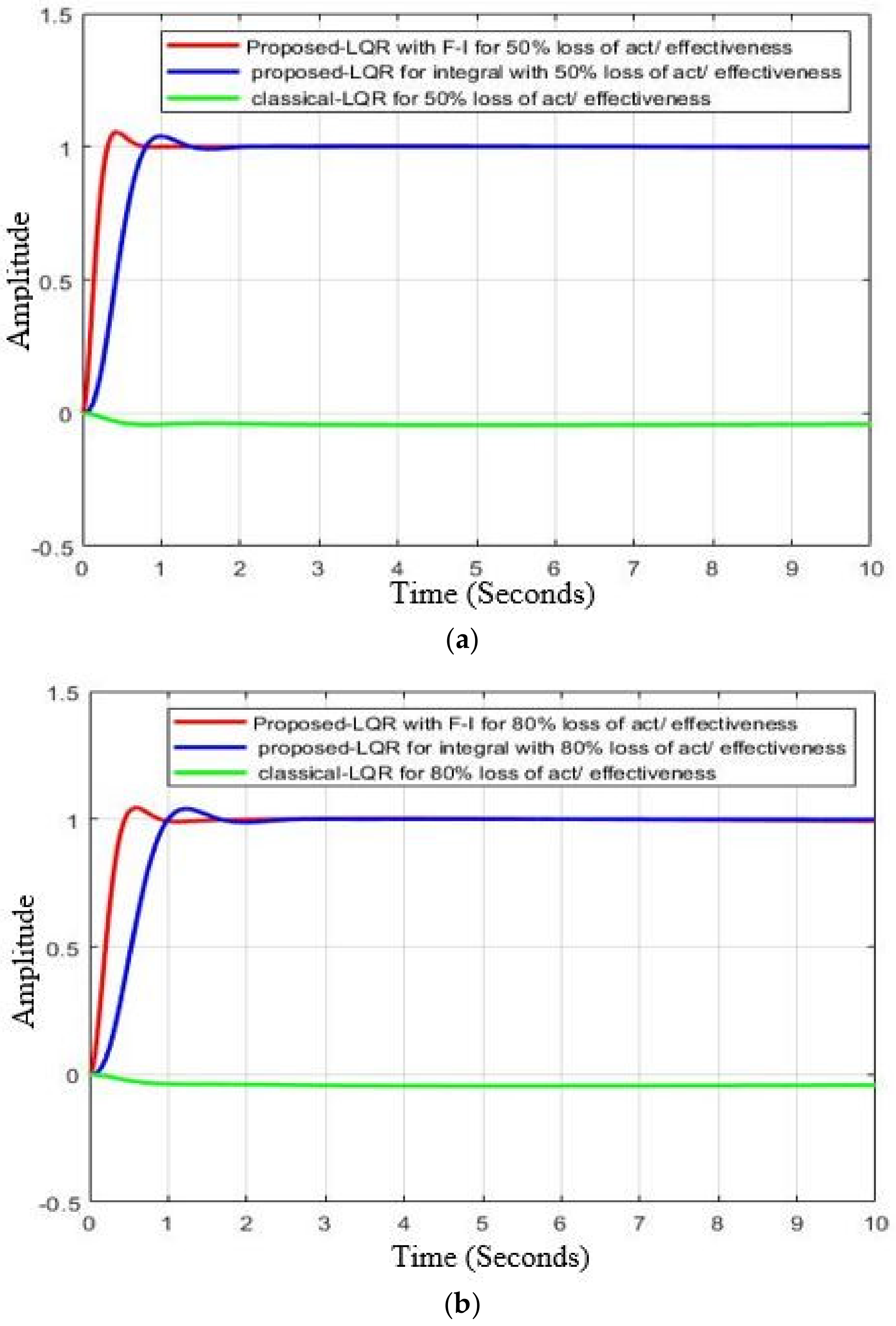
5.3. Proposed LQR-FI Pitch Angle Controller under Fault Flight Condition

The proposed controller can successfully compensate for the 50% and 80% loss of actuator effectiveness faults as shown in Figure 5a,b. Furthermore, Table 1 shows the obtained design parameters of vectors Q n e w ,   R , λ , K I and performance index IAE for the proposed controller compared with a conventional LQR controller in the case of 50% and 80% loss of the actuator gain’s fault.

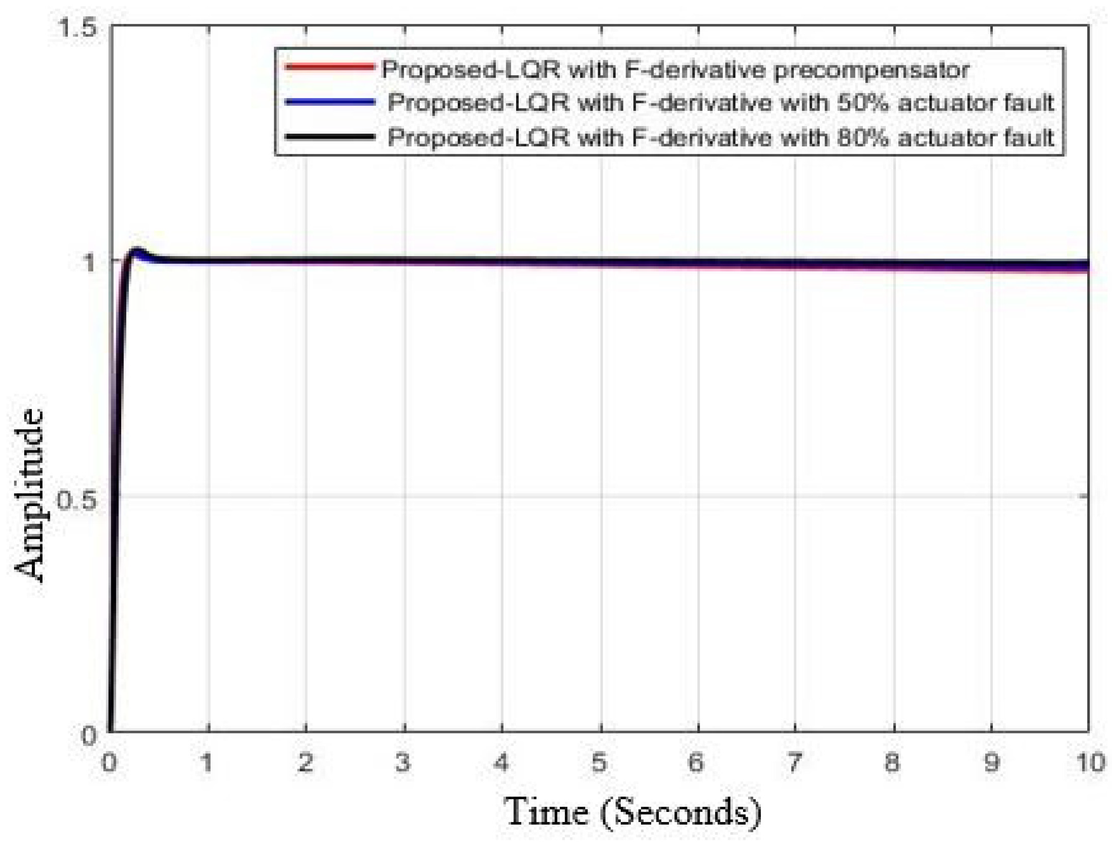
5.4. Proposed Structure with FD Pre-Compensator (LQR-FDC): Fault-Free and Fault Flight Conditions

As explained earlier, the main problem of a non-minimum phase system that occurs when designing a feedback tracking controller is achieving internal stability. In this paper, the internal stability problem is assessed by replacing the fractional-order integral pre-compensator with a fractional−order derivative pre-compensator in the proposed structure. The LQR-FDC control structure produced favorable step responses even in the cases of fault as depicted in Figure 6. However, considering the open-loop step response of the augmented dynamics that was explained earlier in Figure 3b, the open-loop step response still exhibits non-minimum phase dynamics, which may lead to an internal instability problem for some states of the dynamics. This can be appreciated if the results shown in Table 1 for the integral pre-compensator are compared with the derivative compensator. It can be concluded that the LQR-FDC highly penalizes the pitch angle state compared with the other states, which may also lead to the internal stability problem.

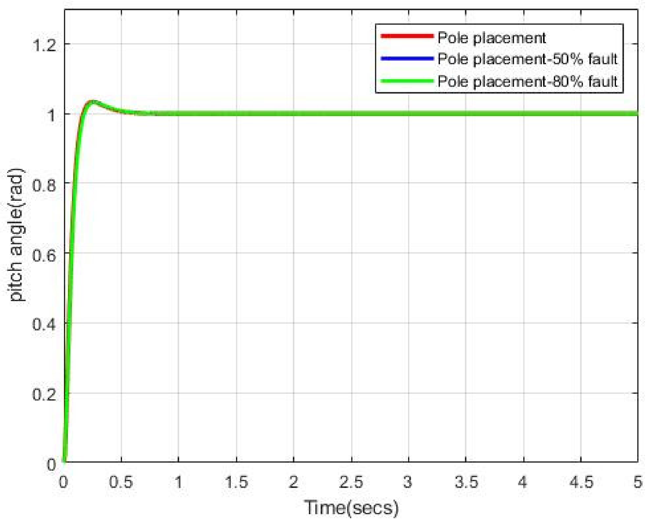
5.5. Proposed LQR-FIC Controller against Pole Placement Controller

Among the techniques frequently found in literature for controlling civil aircraft [59], UAV [60], and military aircrafts [61,62] is the pole placement approach. The proposed LQR-FIC controller is further evaluated by comparing it with the pole placement controller in terms of time and frequency responses under faulty and fault-free conditions. In addition, as described previously, the main obstacle in the classical feedback control loop with NMP dynamics is the problem of internal stability even if the system shows optimal transient and steady-stated time responses. Therefore, for a fair comparison, the desired positions of poles (eigenvalues of the closed−loop system) in the pole-placement controller were selected at the same positions as those captured by the proposed LQR-FIC controller. This, in fact leads to very similar transient responses from both controllers. The forward scaling factor is attached to the pole placement controller at the input of the system to scale the input, and thus force the steady state response to reach the desired level. The value of the scaling factor is selected as the reciprocal of the DC gain of the system to avoid the reversing response of the pole placement controller due to the NMP nature of aircraft altitude control. The main purpose of the proposed controller is to devise a control method to deal with adverse non-minimum phase characteristics in terms of the internal stability problem. It is seen that the proposed method provided better internal stability, which is particularly important in terms of flight quality. The frequency response analysis presented higher gain, phase, and delay margins. Therefore, the evaluation is carried out according to frequency domain analysis to observe the dynamic behavior of the NMP with respect to its internal state stability.
As clearly seen in Figure 7, the pole placement controller with a feedforward scaling factor produced favorable time responses for fault−free and faulty flight conditions. However, as revealed in Figure 8, which represented the Bode plots of the closed-loop system using the pole placement controller, the gain, phase, and delay margins are reduced when compared with the margins of the proposed LQR-FIC controller. Finally, Table 2 presented the results of the pole placement controller that were obtained during the simulation tests.

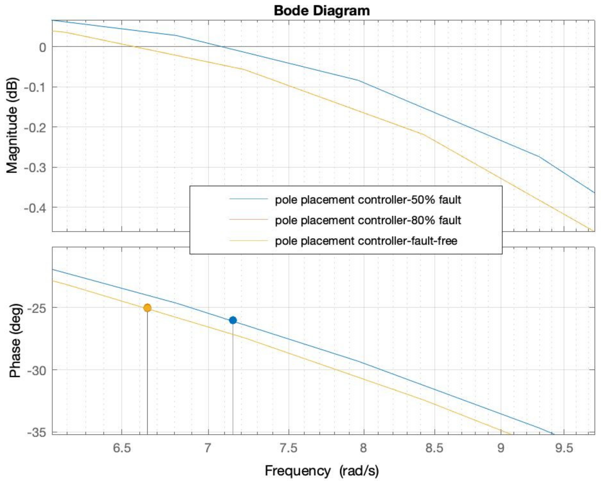
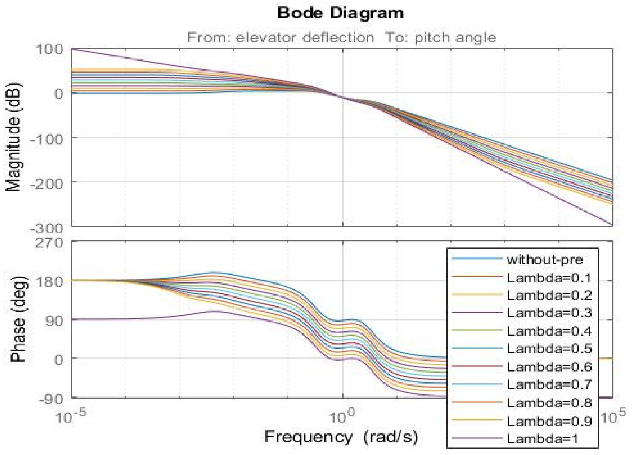
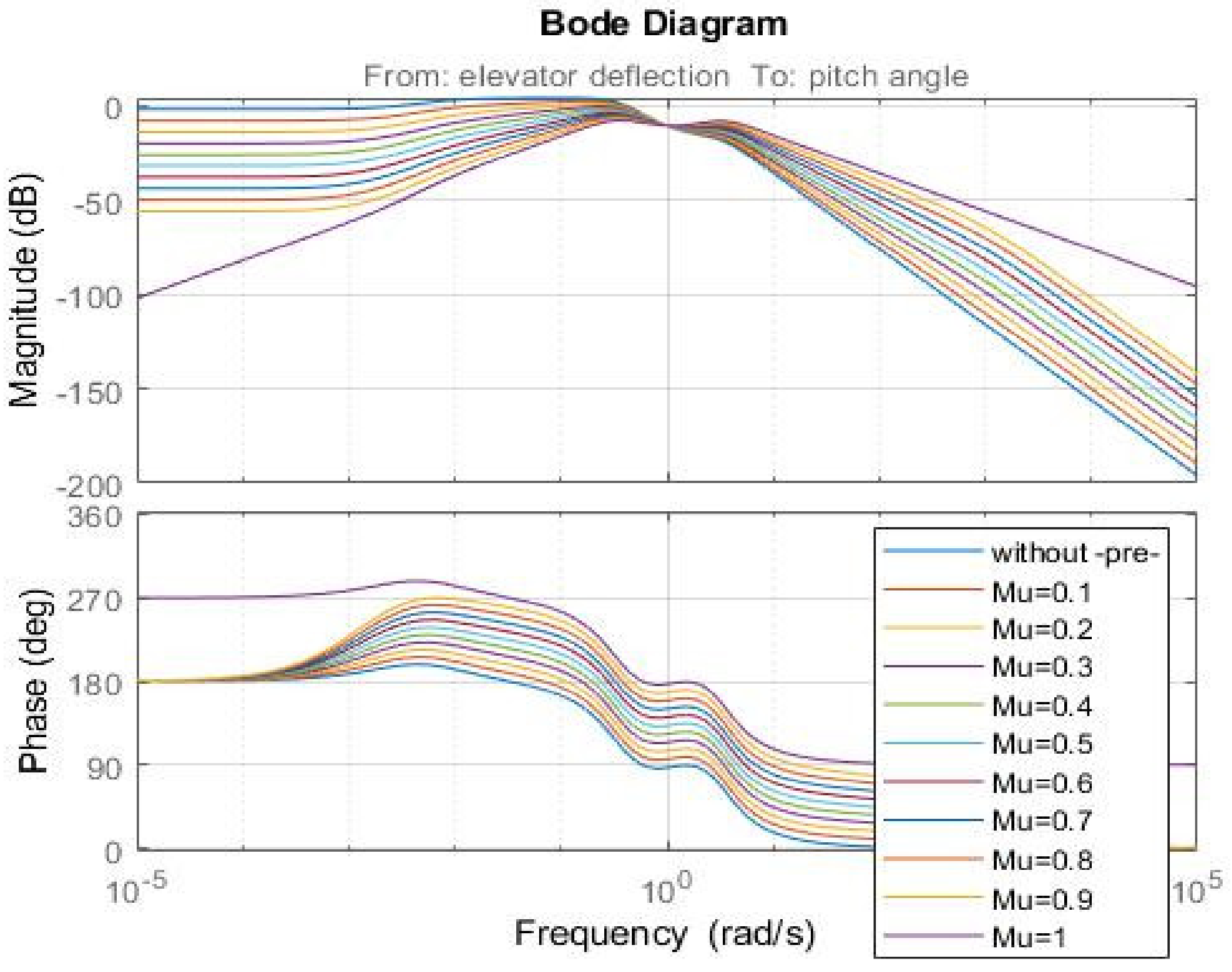
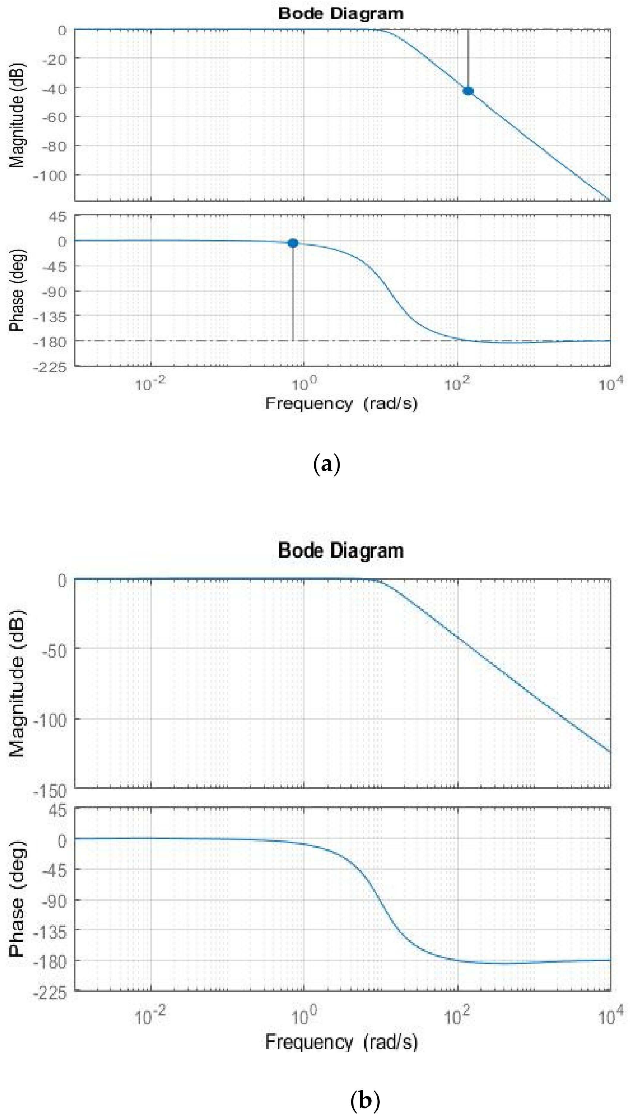
5.6. Effect of Fractional-Order-Based Pre-Compensators on the Phase and Gain Margins of Open- and Closed-Loop Systems

It would be more useful and provide a better evaluation of the effects of both pre-compensators that were demonstrated in the frequency domain by comparing the gain, phase, and delay margins of the augmented dynamic (Open-loop response) with the gain, phase, and delay margins of closed-loop response.
Moreover, the comparison of the two pre-compensators in the frequency domain to emphasize the effectiveness of the compensators removing the limitations of the feedback control system with the non-minimum phase dynamics should be performed. Figure 9 and Figure 10 show comparisons of the Bode diagram of an open-loop response frequency response according to the values of λ and μ with and without the use of FI and FD pre-compensators, respectively. It can be observed from Figure 9 that the fractional integral pre−compensator makes the augmented system more phase lagging. In contrast to this observation, the fractional derivative pre−compensator increases the phase margin, as shown in Figure 10, that is it increases the phase margin of the feedback system.
For a visual comparison of the time responses of the closed-loop systems, Figure 4 presents the fault-free condition, Figure 5a,b presents the 50% and 80% faulty cases. For a visual comparison of the frequency responses that reveal the relative stability of the closed-loop system, the Bode plots are presented for the same fault-free and faulty cases in Figure 11a,b respectively. In addition, the Bode plots in the case of fractional-order derivative (FD) for the fault-free and under 50% faulty cases are depicted in Figure 12a,b, respectively. Accordingly, the associated frequency response performance values are presented in Table 3. All these simulation tests reveal that the closed-loop system is more robust in the case of having the fractional-order integral (FIC) pre-compensator than having the fractional-order derivative compensator in terms of gain, phase, and delay margins as shown in Figure 11a,b, and Table 3. This is achieved owing to simultaneously optimized feedback controller gains and the pre-compensator parameters.

6. Conclusions

In this article, a novel combination structure of the LQR and fractional integral controller (LQR-FIC) was developed to compensate for the non-minimum phase dynamics of Boeing 747 aircraft. A fractional-order integrator was employed as a pre-compensator to convert the longitudinal dynamics of the aircraft from the non-minimum phase dynamics to the minimum phase. Then, the LQR was implemented to find an optimal control law for the augmented dynamics. Nevertheless, the LQR optimal feedback gains and fractional integral parameters are simultaneously adjusted employing the proposed PSO optimization algorithm to create a more flexible combination of controllers with fractional order pre-compensators. Finally, the proposed controller was evaluated in the cases of fault-free flight conditions, internal stability problems, phase and gain margins, and for 50% and 80% losses of actuator effectiveness faults.
In the current study, it is observed that in all implementations with fractional order compensators (FIC and FDC) and full state feedback (pole placement) control systems, the results proved all configurations under examination could ward off the adverse effects of non−minimum phase dynamics when analyzed in the time domain. However, as matter of fact, the frequency domain analysis revealed that a fractional-order integral pre-compensator represents more robust results with stabilized internal states compared with the fractional-order derivative pre-compensator and pole placement methods. Although the LQR-FDC (adaptive fractional−order derivative) and pole placement controllers produced promising results in the cases of faults, the open−loop dynamics exhibited non−minimum phase characteristics, which may lead to internal instability. The proposed control structure, namely adaptive fractional-order integral controller, LQR-FIC showed superior results in the time and frequency response analyses.

Author Contributions

Methodology, software implementation, A.S.E.; conceptualization, formal analysis, investigation, A.S.E. and S.N.E.; writing—original draft preparation, A.S.E.; writing—review and editing, S.N.E., A.A.P., M.M.R. and S.N.P. All authors have read and agreed to the published version of the manuscript.

Funding

This research received no external funding.

Institutional Review Board Statement

Not applicable.

Informed Consent Statement

Not applicable.

Data Availability Statement

Not applicable.

Acknowledgments

This work is produced out of the studies of Aisha Sir Elkhatem under the advisory of Seref Naci Engin. This project was funded by the Deanship of Scientific Research (DSR), King Abdulaziz University, Jeddah, under grant No. (D-145-135-1443). The authors, therefore, gratefully acknowledge DSR technical and financial support.

Conflicts of Interest

The authors declare that there is no conflict of interest regarding the publication of this paper.

Appendix A

F s = 1 s l a m b d a Approximation of the Fractional-Order Integrator using the Oustaloup Method
s 0.1       0.50119 s + 568.3 s + 161.8 s + 46.09 s + 13.13 s + 3.739 s + 1.065 s + 0.3033 s + 0.08637 s + 0.0246 s + 0.007006   s + 0.001995     s + 501.2 s + 142.7 s + 40.65 s + 11.58 s + 3.297 s + 0.9391 s + 0.2675 s + 0.07618 s + 0.0217 s + 0.006179 s + 0.00176      
F s = s M u Approximation of the fractional−order integrator using Oustaloup method
s 0.1 1995.3   s + 501.2 s + 142.7 s + 40.65 s + 11.58 s + 3.297 s + 0.9391 s + 0.2675 s + 0.07618   s + 0.0217   s + 0.006179   s + 0.00176 s + 568.3 s + 1000 s + 161.8 s + 46.09 s + 13.13 s + 3.739 s + 1.065 s + 0.3033 s + 0.08637   s + 0.0246   s + 0.007006   s + 0.001995
K I s 0.1 = 75.176   s + 568.3 s + 161.8 s + 46.09 s + 13.13 s + 3.739 s + 0.08637 s + 0.0246 s + 0.007006   s + 0.001995 s + 1.065 s + 0.3033 s + 501.2 s + 142.7 s + 40.65 s + 11.58 s + 3.297 s + 0.07618 s + 0.0217 s + 0.006179 s + 0.00176   s + 0.9391 s + 0.2675    
K l q r = 0.010   0.011     0.0015   0.0107     0.0172   0.0323       1.0298   0.1476       0.0012   0.008       0.0013   0.00         0.0025   0.00     0.0046   0.00       0.0086   0.00         0.0161   0.00       0.0296   0.00       0.0519   0.00         0.0743   0.0001         0.0698   0.0001         0.048   0.0001         0.0306   0.0001         0.0001   0.0006         0.0002   0.001         0.0002   0.0014         0.0002   0.0013         0.0002   0.001         0.0001   0.0006         0.001   0.0004         0.0001   0.0002         0.0001   0.0001         0.0001   0.0001         0.0001   0.0001      

Appendix B

The augmented state-space matrices for lambda = 0.1.
A e x g = 2.125 0.05 0.5384 0.3522 3.627 0.1327 1 0 0 1.0578 7 0 0 0 0 0 0 0 0 0 0 0 0 0 0 0 0 0 0 0 0 0 0 0 0 0 0 0 0 0 0 0 0 0 0 0 0 0 0 0 0 0 0 0 0 1.813 0 0.0003379 4.733 9.794 0.03635 2.428 4.582 e 8 0.01276 0 0 0 13.6 13.6 0 0 0 0 0 0 0 0 0 0 0 0 0 0 0 0 0 0 0 0 0 0 0 0 0 0 0 0 0 0 0 0 0 0 0 0 0 0 0 0 0 0 0 0 0 0 0 0 0 0 0 0 0 0 0 0 0 0 0 0 0 0 0 0 0 0 0 0.2247 0.421 0.7889 1.663 e 7 3.117 e 7 5.84 e 7 0.07622 0.1428 0.2676 0 0 0 0 0 0 0.00176 0.0004413 0.0008269 0 0.006179 0.001549 0 0 0.0217 0 0 0 0 0 0 0 0 0 0 0 0 0 0 0 0 0 0 0 0 0 0 0 0 0 0 0 0 0 0 0 0 0 0 0 0 0 0 0 0 0 0 0 0 0 0 0 0 0 0 0 0 0 0 0 0 0 1.478 2.77 5.19 1 e 6 2.051 e 6 3.843 e 6 0.5015 0.9397 1.761 0 0 0 0 0 0 0.001549 0.002903 0.00544 0.002903 0.00544 0.01019 0.0054 0.01019 0.0191 0.07618 0.0191 0.03579 0 0.2675 0.06707 0 0 0.9391 0 0 0 0 0 0 0 0 0 0 0 0 0 0 0 0 0 0 0 0 0 0 0 0 0 0 0 0 0 0 0 0 0 0 0 0 0 0 0 0 0 0 0 0 0 0 0 0 9.726 18.22 34.15 7.2 e 6 1.349 e 5 2 e 5 3.3 6.183 11.59 0 0 0 0 0 0 0.01019 0.0191 0.03579 0.0191 0.03579 0.06707 0.03579 0.06707 0.1257 0.06707 0.1257 0.2355 0.1257 0.2355 0.4413 0.2355 0.4413 0.8269 3.297 0.8269 1.549 0 11.58 2.903 0 0 40.65 0 0 0 0 0 0 0 0 0 0 0 0 0 0 0 0 0 0 0 0 0 0 0 0 0 0 0 0 0 0 0 0 0 0 0 0 0 0 0 63.99 119.9 0.2 e 0 4.737 e 5 8.877 e 5 0.001293 21.71 40.68 0.0001018 0 0 0 0 0 0 0.06707 0.1257 0 0.1257 0.2355 0 0.2355 0.4413 0 0.4413 0.8269 0 0.8269 1.549 0 1.549 2.903 0 2.903 5.44 0 5.44 10.19 0 10.19 19.1 0 142.7 35.79 0 0 501.2 0 0 0 0.00176 0 0 0 0 0 0 0 0 0 0 0 0 0 0 0 0 0 0 0 0 0 0 0 0 0 0 0 0 0 0 0.3 e 3 0.0007077 0.001326 0.002422 0.004539 0.008505 0.0001908 0.0003576 0.00067 0 0 0 0 0 0 0 0 0 0 0 0 0 0 0 0 0 0 0 0 0 0 0 0 0 0 0 0 0 0 0 0 0 0 0 0 0 0 0 0.0004413 0.0008269 0.001549 0.006179 0.001549 0.002903 0 0.0217 0.00544 0 0 0.07618 0 0 0 0 0 0 0 0 0 0 0 0 0 0 0 0 0 0 0 0 0 0.002485 0.004656 0.008725 0.01594 0.02986 0.05596 0.001255 0.002352 0.004408 0 0 0 0 0 0 0 0 0 0 0 0 0 0 0 0 0 0 0 0 0 0 0 0 0 0 0 0 0 0 0 0 0 0 0 0 0 0 0 0.002903 0.00544 0.01019 0.00544 0.01019 0.0191 0.01019 0.0191 0.03579 0.0191 0.03579 0.06707 0.2675 0.06707 0.1257 0 0.9391 0.2355 0 0 3.297 0 0 0 0 0 0 0 0 0 0 0 0 0.01635 0.03064 0.1049 0.1965 0.00826 0.01548 0 0 0 0 0 0 0 0 0 0 0 0 0 0 0 0 0 0 0 0 0 0 0 0 0 0 0.0191 0.03579 0.03579 0.06707 0.06707 0.1257 0.1257 0.2355 0.2355 0.4413 0.4413 0.8269 0.8269 1.549 11.58 2.903 0 40.65 0 0 0 0 0.05741 0.1076 0.3682 0.6899 0.029 0.05435 0 0 0 0 0 0 0 0 0 0 0 0 0 0 0 0 0 0 0 0 0 0 0 0 0 0 0.06707 0.1257 0.1257 0.2355 0.2355 0.4413 0.4413 0.8269 0.8269 1.549 1.549 2.903 2.903 5.44 5.44 10.19 10.19 19.1 142.7 35.79 0 501.2
C a u g   = 0 0 1 1 0.2028 0.1321 1.775 3.674 0 0 0 1 1 0 0 0 0 1 0 0 0 0 0 0 1 0 0 0 0 0.01364 6.24 e 8 1.169 e 7 2.191 e 7 4.105 e 7 0 0 0 0 0 0 0 0 0 0 0 0 0 0 0 1 0 0 0 0 0 0 0 0 0 7.693 e 7 1.441 e 6 2.701 e 6 5.061 e 6 9.48 e 6 0 0 0 0 0 0 0 0 0 0 0 0 0 0 0 0 0 0 0 0 0 0 0 0 1.777 e 5 3.33 e 5 0.000485 0.0009087 0 0 0 0 0 0 0 0 0 0 0 0 0 0 0 0 0 0 0 0 0.001703 0.003191 0.005979 0.0112 0 0 0 0 0 0 0 0 0 0 0 0 0 0 0 0 0 0 0 0 0.02099 0.03934 0.07371 0.1381 0 0 0 0 0 0 0 0 0 0 0 0 0 0 0 0 0 0 0.1381 0.2588 0 0 0 0 0 0 0 0
B a u g =   117.1   8.671 e 5 39.74 0 0 0.1228 0.23   0.4311 0.8077   1.514 2.836 5.314   9.958     18.66 34.96   65.52   0 0 0 0 0 0 0 0 0 0 0     0.1051 0.6739 0.05309 0 0 0 0 0 0 0 0 0 0 0 0 0 0.1228 0.23 0.4311 0.8077 1.514 2.836   5.314 9.958 18.66 34.96 65.52  

References

  1. Boeing Commercial Airplanes. Statistical Summary of Commercial Jet Airplane Accidents; Boeing Commercial Airplanes: Seattle, WA, USA, 2015; p. 24. [Google Scholar]
  2. Boeing Operations. Statistical Summary of Commercial Jet Airplane Accidents Worldwide Operations|1959–2016; Boeing Commercial Airplanes: Seattle, WA, USA, 2017. [Google Scholar]
  3. Airbus. A Statistical Analysis of Commercial Aviation Accidents 1958–2019; Airbus: Blagnac, France, 2020; p. 22. [Google Scholar]
  4. Liao, Y.K.; Liao, Y.K. Limitations of non-minimum-phase feedback systems. Int. J. Control 1984, 40, 1003–1013. [Google Scholar] [CrossRef]
  5. Sidi, M. Gain–bandwidth limitations of feedback systems with non-minimum-phase plants. Int. J. Control 1997, 67, 731–744. [Google Scholar] [CrossRef]
  6. Skogestad, S.; Postlethwaite, I. Multivariable Feedback Control—Analysis and Design. IEEE Control Syst. 2007, 27, 80–81. [Google Scholar] [CrossRef]
  7. Estrada, M. Toward the Control of Non-Linear, Non-Minimum Phase Systems via Feedback Linearization and Reinforcement Learning. Master’s Thesis, University of California, Berkeley, CA, USA, 2021. [Google Scholar]
  8. Benvenuti, L.; di Benedetto, M.D.; Grizzle, J.W. Approximate output tracking for nonlinear non-minimum phase systems with an application to flight control. Int. J. Robust Nonlinear Control 1994, 4, 397–414. [Google Scholar] [CrossRef]
  9. Zhao, H.; Chen, D. A finite energy property of stable inversion to nonminimum phase nonlinear systems. IEEE Trans. Autom. Control 1998, 43, 1170–1174. [Google Scholar] [CrossRef]
  10. Rajput, J.; Weiguo, Z. Fundamental methodologies for control of nonlinear non minimum-phase systems: An overview. Proc. Inst. Mech. Eng. Part I J. Syst. Control Eng. 2014, 228, 553–564. [Google Scholar] [CrossRef]
  11. Chen, D.; Paden, B. Stable inversion of nonlinear non-minimum phase systems. Int. J. Control 1996, 64, 81–97. [Google Scholar] [CrossRef]
  12. Zhou, S.; Helwa, M.K.; Schoellig, A.P. An Inversion-Based Learning Approach for Improving Impromptu Trajectory Tracking of Robots with Non-Minimum Phase Dynamics. IEEE Robot. Autom. Lett. 2018, 3, 1663–1670. [Google Scholar] [CrossRef] [Green Version]
  13. Guardabassi, G.O.; Savaresi, S.M. Approximate linearization via feedback—An overview. Automatica 2001, 37, 1–15. [Google Scholar] [CrossRef]
  14. Zietkiewicz, J. Non-minimum phase properties and feedback linearization control of nonlinear chemical reaction. In Proceedings of the 20th International Conference on Methods and Models in Automation and Robotics (MMAR), Miedzyzdroje, Poland, 24–27 August 2015. [Google Scholar] [CrossRef]
  15. Zhao, S. Practical Solutions to the Non-Minimum Phase and Vibration Problems under the Disturbance Rejection Paradigm. Ph.D. Thesis, Cleveland State University, Cleveland, OH, USA, 2012. [Google Scholar]
  16. Lee, H.P.; Clemens, J.W.; Youssef, H.M. Dynamic Inversion Flight Control Design for Aircraft with Non-Minimum Phase Response; SAE Technical Paper Series; SAE International: Warrendale, PA, USA, 2011. [Google Scholar] [CrossRef]
  17. Hoagg, J.B.; Bernstein, D.S. Nonminimum-phase zeros-much to do about nothing-classical control-revisited part II. IEEE Control Syst. 2007, 27, 45–57. [Google Scholar] [CrossRef]
  18. Patrick, M.J.; Ishak, N.; Rahiman, M.H.F.; Tajjudin, M.; Adnan, R. Modeling and controller design for non-minimum phase system with application to XY-table. In Proceedings of the 2011 IEEE Control and System Graduate Research Colloquium, Shah Alam, Malaysia, 27–28 June 2011. [Google Scholar]
  19. Panjapornpon, C.; Soroush, M. Control of non-minimum-phase nonlinear systems through constrained input-output linearization. In Proceedings of the American Control Conference, Minneapolis, MN, USA, 14–16 June 2006. [Google Scholar] [CrossRef]
  20. Terra, M.H.; Cerri, J.P.; Ishihara, J.Y. Optimal robust linear quadratic regulator for systems subject to uncertainties. IEEE Trans. Autom. Control 2014, 59, 2586–2591. [Google Scholar] [CrossRef]
  21. Tanaka, R.; Koga, T. An approach to linear active disturbance rejection controller design with a linear quadratic regulator for a non-minimum phase system. In Proceedings of the 2019 Chinese Control Conference (CCC), Guangzhou, China, 27–30 July 2019; Volume 2019, pp. 250–255. [Google Scholar] [CrossRef]
  22. Benosman, M.; Le Vey, G. Control of flexible manipulators: A survey. Robotica 2004, 22, 533–545. [Google Scholar] [CrossRef]
  23. Ghazali, R.; Sam, Y.M.; Rahmat, M.F.A. Point-to-point trajectory tracking with two-degree-of-freedom robust control for a non-minimum phase electro-hydraulic system. In Proceedings of the 10th World Congress on Intelligent Control and Automation, Beijing, China, 6–8 July 2012; pp. 2661–2668. [Google Scholar] [CrossRef]
  24. Klemm, V.; Morra, A.; Gulich, L.; Mannhart, D.; Rohr, D.; Kamel, M.; de Viragh, Y.; Siegwart, R. LQR-Assisted Whole-Body Control of a Wheeled Bipedal Robot with Kinematic Loops. IEEE Robot. Autom. Lett. 2020, 5, 3745–3752. [Google Scholar] [CrossRef]
  25. Blight, J.D.; Dailey, R.L.; Gangsaas, D. Practical control law design for aircraft using multivariable techniques. Int. J. Control 1994, 59, 93–137. [Google Scholar] [CrossRef]
  26. Balas, G.J. Flight control law design: An industry perspective. Eur. J. Control 2003, 9, 207–226. [Google Scholar] [CrossRef]
  27. Peng, C.; Ma, J. Adaptive Online Data-Driven Tracking Control for Highly Flexible Aircrafts with Partial Observability. IEEE Access 2020, 8, 192844–192856. [Google Scholar] [CrossRef]
  28. Li, Z.; Zhou, W.; Liu, H. Robust Controller Design of Non-minimum Phase Hypersonic Aircrafts Model based on Quantitative Feedback Theory. J. Astronaut. Sci. 2020, 67, 137–163. [Google Scholar] [CrossRef]
  29. Al-Hiddabi, S.A.; McClamroch, N.H. Output tracking for nonlinear non-minimum phase VTOL aircraft. In Proceedings of the 37th IEEE Conference on Decision and Control (Cat. No.98CH36171), Tampa, FL, USA, 18 December 1998; Volume 4, pp. 4573–4577. [Google Scholar] [CrossRef]
  30. Kim, S.; Horspool, K.R. Nonlinear controller design for non-minimum phase flight system enhanced by adaptive elevator algorithm. In Proceedings of the AIAA Scitech 2020 Forum, Orlando, FL, USA, 6–10 January 2020; Volume 1, pp. 1–24. [Google Scholar] [CrossRef]
  31. Tomlin, C.; Lygeros, J.; Benvenuti, L. Output tracking for a non-minimum phase dynamic CTOL aircraft model. In Proceedings of the 34th IEEE Conference on Decision and Control, New Orleans, LA, USA, 13–15 December 1995. [Google Scholar] [CrossRef] [Green Version]
  32. Liu, Z.; Hu, X.; Wang, X.; Guo, Y. Robust Adaptive Control for Uncertain Input Delay MIMO Nonlinear Non-Minimum Phase System: A Fuzzy Approach. IEEE Access 2020, 8, 154143–154152. [Google Scholar] [CrossRef]
  33. Ahmadi, A.; Mohammadi-Ivatloo, B.; Anvari-Moghaddam, A.; Marzband, M. Optimal robust LQI controller design for Z-source inverters. Appl. Sci. 2020, 10, 7260. [Google Scholar] [CrossRef]
  34. Souza, D.A.; de Mesquita, V.A.; Reis, L.L.N.; Silva, W.A.; Batista, J.G. Optimal LQI and PID Synthesis for Speed Control of Switched Reluctance Motor Using Metaheuristic Techniques. Int. J. Control Autom. Syst. 2021, 19, 221–229. [Google Scholar] [CrossRef]
  35. Birs, I.; Nascu, I.; Ionescu, C.; Muresan, C. Event-based fractional order control. J. Adv. Res. 2020, 25, 191–203. [Google Scholar] [CrossRef] [PubMed]
  36. De Almeida, A.M.; Lenzi, M.K.; Lenzi, E.K. A survey of fractional order calculus applications of multiple-input, multiple-output (Mimo) process control. Fractal Fract. 2020, 4, 22. [Google Scholar] [CrossRef]
  37. Shi, X.; Cheng, Y.; Yin, C.; Zhong, S.; Huang, X.; Chen, K.; Qiu, G. Adaptive Fractional-Order SMC Controller Design for Unmanned Quadrotor Helicopter under Actuator Fault and Disturbances. IEEE Access 2020, 8, 103792–103802. [Google Scholar] [CrossRef]
  38. Cieslak, J.; Henry, D.; Zolghadri, A. Fault tolerant flight control: From theory to piloted flight simulator experiments. IET Control Theory Appl. 2010, 4, 1451–1464. [Google Scholar] [CrossRef]
  39. Nie, C. Observer-Based Robust Fault Estimation For Fault-Tolerant Control. Ph.D. Thesis, Department of Engineering, The University of Hull, Hull, UK, 2012. [Google Scholar]
  40. Liu, Y.; Dong, X.; Ren, Z.; Cooper, J. Fault-tolerant control for commercial aircraft with actuator faults and constraints. J. Frankl. Inst. 2019, 356, 3849–3868. [Google Scholar] [CrossRef] [Green Version]
  41. Zhang, Y.; Jiang, J. Bibliographical review on reconfigurable fault-tolerant control systems. Annu. Rev. Control 2008, 32, 229–252. [Google Scholar] [CrossRef]
  42. Xingjian, W.; Shaoping, W.; Zhongwei, Y.; Chao, Z. Active fault-tolerant control strategy of large civil aircraft under elevator failures. Chin. J. Aeronaut. 2015, 28, 1658–1666. [Google Scholar] [CrossRef] [Green Version]
  43. Wang, R.; Wang, J. Passive Actuator Fault-Tolerant Control for a Class of Overactuated Nonlinear Systems and Applications to Electric Vehicles. IEEE Trans. Veh. Technol. 2013, 62, 972–985. [Google Scholar] [CrossRef]
  44. Mirshams, M.; Khosrojerdi, M.; Hasani, M. Passive fault-tolerant sliding mode attitude control for flexible spacecraft with faulty thrusters. Proc. Inst. Mech. Eng. Part G J. Aerosp. Eng. 2014, 228, 2343–2357. [Google Scholar] [CrossRef]
  45. Ijaz, S.; Hamayun, M.T.; Yan, L.; Shi, C. Active fault-tolerant control for vertical tail damaged aircraft with dissimilar redundant actuation system using integral sliding mode control. J. Mech. Eng. Sci. 2018, 29, 1–18. [Google Scholar] [CrossRef]
  46. Abbaspour, A.; Yen, K.K.; Forouzannezhad, P.; Sargolzaei, A. A Neural Adaptive Approach for Active Fault-Tolerant Control Design in UAV. IEEE Trans. Syst. Man Cybern. Syst. 2018, 50, 3401–3411. [Google Scholar] [CrossRef]
  47. Sun, X.; Wang, X.; Zhou, Z.; Zhou, Z. Active Fault-Tolerant Control Strategy for More Electric Aircraft under Actuation System Failure. J. Actuators 2020, 9, 122. [Google Scholar] [CrossRef]
  48. Zhang, Y.M.; Jiang, J. Issues on integration of fault diagnosis and reconfigurable control in active fault-tolerant control systems. IFAC Proc. 2006, 39, 1437–1448. [Google Scholar] [CrossRef]
  49. Lee, T.H.; Lim, C.P.; Nahavandi, S.; Roberts, R.G. Observer-Based H_inf Fault-Tolerant Control for Linear Systems with Sensor and Actuator Faults. IEEE Syst.J. 2019, 13, 1981–1990. [Google Scholar] [CrossRef]
  50. Ru, J.; Li, X.R. Variable-Structure Multiple-Model Approach to Fault Detection, Identification, and Estimation. IEEE Trans. Control Syst. Technol. 2008, 16, 1029–1038. [Google Scholar] [CrossRef]
  51. Sweilam, N.H.; AL-Mekhlafi, S.M.; Baleanu, D. A hybrid fractional optimal control for a novel Coronavirus (2019-nCov) mathematical model. J. Adv. Res. 2020, 32, 149–160. [Google Scholar] [CrossRef]
  52. Esteban, A.M. Aircraft Applications of Fault Detection and Isolation Techniques. Ph.D. Thesis, University of Minnesota, Minneapolis, MN, USA, 2004. [Google Scholar]
  53. Matychyn, I.; Onyshchenko, V. Optimal control of linear systems of arbitrary fractional order. Fract. Calculus Appl. Anal. 2019, 22, 170–179. [Google Scholar] [CrossRef]
  54. Wang, L. Model Predictive Control System Design and Implementation Using MATLAB; Advances in Industrial Control; Grimble, M.J., Johnson, M.A., Eds.; Springer Science & Business Media: Berlin/Heidelberg, Germany, 2008; ISSN 1430-9491. [Google Scholar]
  55. Viaro, U. On the rational approximation of fractional order systems. In Proceedings of the 2011 16th International Conference on Methods & Models in Automation & Robotics, Miedzyzdroje, Poland, 22–25 August 2011; pp. 132–136. [Google Scholar]
  56. Ranaee, V.; Ebrahimzadeh, A.; Ghaderi, R. Application of the PSO–SVM model for recognition of control chart patterns. J. ISA Trans. 2010, 49, 577–586. [Google Scholar] [CrossRef]
  57. Barbieri, R.; Barbieri, N.; De Lima, K.F. Some applications of the PSO for optimization of acoustic filters. J. Appl. Acoust. 2015, 89, 62–70. [Google Scholar] [CrossRef]
  58. Doctor, S.; Venayagamoorthy, G.K.; Gudise, V.G. Optimal PSO for collective robotic search applications. In Proceedings of the 2004 Congress on Evolutionary Computation (IEEE Cat. No. 04TH8753), Portland, OR, USA, 19–23 June 2004; pp. 1390–1395. [Google Scholar]
  59. Guo, W. Gain Scheduling for a Passengeraircraft Control System to Satisfy Handling Qualities; Cranfield University: Silsoe, UK, 2010. [Google Scholar]
  60. Qian, Z.Z.; Zhai, X.H. Flight Control Law Design via Pole Placement. Adv. Mater. Res. 2012, 466–467, 1202–1206. [Google Scholar] [CrossRef]
  61. Andrade, J.P.P.; Campos, V.A.F. Robust Control of a Dynamic Model of an F-16 Aircraft with Improved Damping through Linear Matrix Inequalities. World Acad. Sci. Eng. Technol. Int. J. Comput. Inf. Eng. 2017, 11, 230–236. [Google Scholar]
  62. Wahab, A.A.; Mamat, R.; Shamsudin, S.S. The Effectiveness of Pole Placement Method in Control System Design for an Autonomous Helicopter Model in Hovering Flight. Int. J. Integr. Eng. 2009, 1, 33–46. [Google Scholar]
Figure 1. Open−loop step response of Boeing 747 pitch angle dynamic.
Applsci 11 11705 g001
Figure 2. Proposed LQR-FIC controller scheme.
Applsci 11 11705 g002
Figure 3. (a) Open−loop step responses of augmented pitch angle control-fractional integral, and (b) open−loop step response for augmented pitch angle control − fractional derivative.
Applsci 11 11705 g003
Figure 4. Pitch angle step responses to various controllers.
Applsci 11 11705 g004
Figure 5. Pitch angle step response with (a) 50% fault and (b) 80% fault.
Applsci 11 11705 g005
Figure 6. Pitch angle step response with and without faults.
Applsci 11 11705 g006
Figure 7. Pitch angle step response with and without faults—pole placement controller.
Applsci 11 11705 g007
Figure 8. Closed-loop Bode plots of pole placement.
Applsci 11 11705 g008
Figure 9. Open-loop Bode plots of the plant with and without FI compensator.
Applsci 11 11705 g009
Figure 10. Open-loop Bode plots of the plant with and without FD compensator.
Applsci 11 11705 g010
Figure 11. (a) Closed-loop Bode plots of LQR-FI compensator for λ = 0.1 : fault−free, and (b) closed-loop Bode plots of LQR-FI compensator with 50% loss of actuator effectiveness for λ = 0.1 .
Applsci 11 11705 g011
Figure 12. (a) Closed-loop Bode plots of LQR-FD compensator for λ = 0.6 : fault-free, and (b) closed-loop Bode plots of LQR-FD compensator with 50% loss of actuator effectiveness for λ = 0.6 .
Applsci 11 11705 g012
Table 1. The numerical results of the proposed controller−based fractional integral/fractional compensator: fault−free and faulty conditions.
ParametersLQR-FIC and LQR-ICLQR-FDCClassical-LQR
Fault-Free50% Fault80% FaultFault-Free50% Fault80% FaultFault-Free50% Fault80% Fault
LQR-FICLQR-ICLQR-FICLQR-ICLQR-FICLQR-ICLQR-FDCLQR-FDCLQR-FDCLQRLQRLQR
IAE0.01380.03860.01830.04530.02550.05680.00430.00610.01011.04361.04161.0428
K I −149.9−150−150−149.9−150−150−150−149.99−150--
λ 0.110.110.110.60.60.5--
Q q 0.010.010.011.28870.01050.80770.010.010.01101010
Q v 0.04090.010.03580.04190.010.02480.010.010.01101010
Q α 0.44530.83180.32580.59530.50150.46840.180.82370.01101010
Q θ 89.472396.188169.4887.98687.74592.616788.72974.16984.8474100010001000
Q h 0.010.010.010.010.010.010.010.010.01101010
R 99.87310079989299.4215797.77986.24999.9998101010
Table 2. Numerical performance results of the pole placement controller.
Controller IAEP1P2P3P4P5Forward Negative Scaling Factor
Pole placement-Fault free0.0704−50.117−10.420−14.27−14.200−1.26−627.4238
Pole placement-50% Fault free0.0728−50.117−47.777−9.29−14.274−1.21−599.9231
Pole placement-80% Fault free0.0728−50.117−47.769−9.29−14.274−1.21−599.9041
Table 3. Obtained numerical results of the closed-loop phase and gain margins.
Adaptive Fractional
Integral Pre-Compensator (AFI)
Adaptive Fractional Derivative
Pre-Compensator (AFD)
Pole Placement
Controller
Gain Margin (dB)42.434.8Inf
Phase Margin (deg)175171155
Delay margin (second)4.30.4190.472
50% loss of actuator effectiveness
Gain Margin (dB)51.248.2Inf
Phase Margin (deg)162162154
Delay margin (sec)1.850.710.37
Publisher’s Note: MDPI stays neutral with regard to jurisdictional claims in published maps and institutional affiliations.

