Computer simulations are planned in several steps. In the initial phase a simplified vehicle model was used, and a large number of simulations was performed in order to compare various approaches of detecting the track curvature and the algorithms for controlling wheelset steering. The performance of selected solution will be consequently assessed by detailed simulation model of an electric locomotive. The simulations focused on the detection of the track radius using simplified vehicle model are described in this study, the simulations focused on the comparison of control algorithms, as well as simulations with detailed vehicle model, will be published in subsequent papers.
Track Radius Estimation
In general, two main approaches for the track radius estimation exist:
Utilization of the track map and detecting the position of the vehicle on the track. This method assumes the knowledge of the curvature along the track, which must be available to the controller, for example in the form of a look up tables. The position of the vehicle on the track could be detected by GPS navigation or by measurement of wheelset revolutions. Integration wheelset revolutions is rather inaccurate due to slips in wheel-rail contacts and unknown value of exact wheel radius. However, it can be refined by track marks at certain known positions. Most of the railway tracks are already equipped with such marks, for example balise transmission modules of European Train Control System could be utilized for this purpose.
Estimation of the track radius using on board sensors.
Although vehicle positioning systems based on the GPS navigation exist and achieve continuously improving parameters in terms of accuracy and reliability, estimation of track radius by of onboard sensors was finally chosen. The main advantages of an onboard system are:
independence of GPS signal which can be difficult to reach in urban areas with high buildings around the track, deep valleys, or in tunnel sections;
independence of wheel radius measurement or estimation;
independence of the track map. This gives the possibility to operate the vehicle on any track without the need to provide the controller by track data, which can be very important in the event of unexpected obstacles on the track, lockouts, etc.
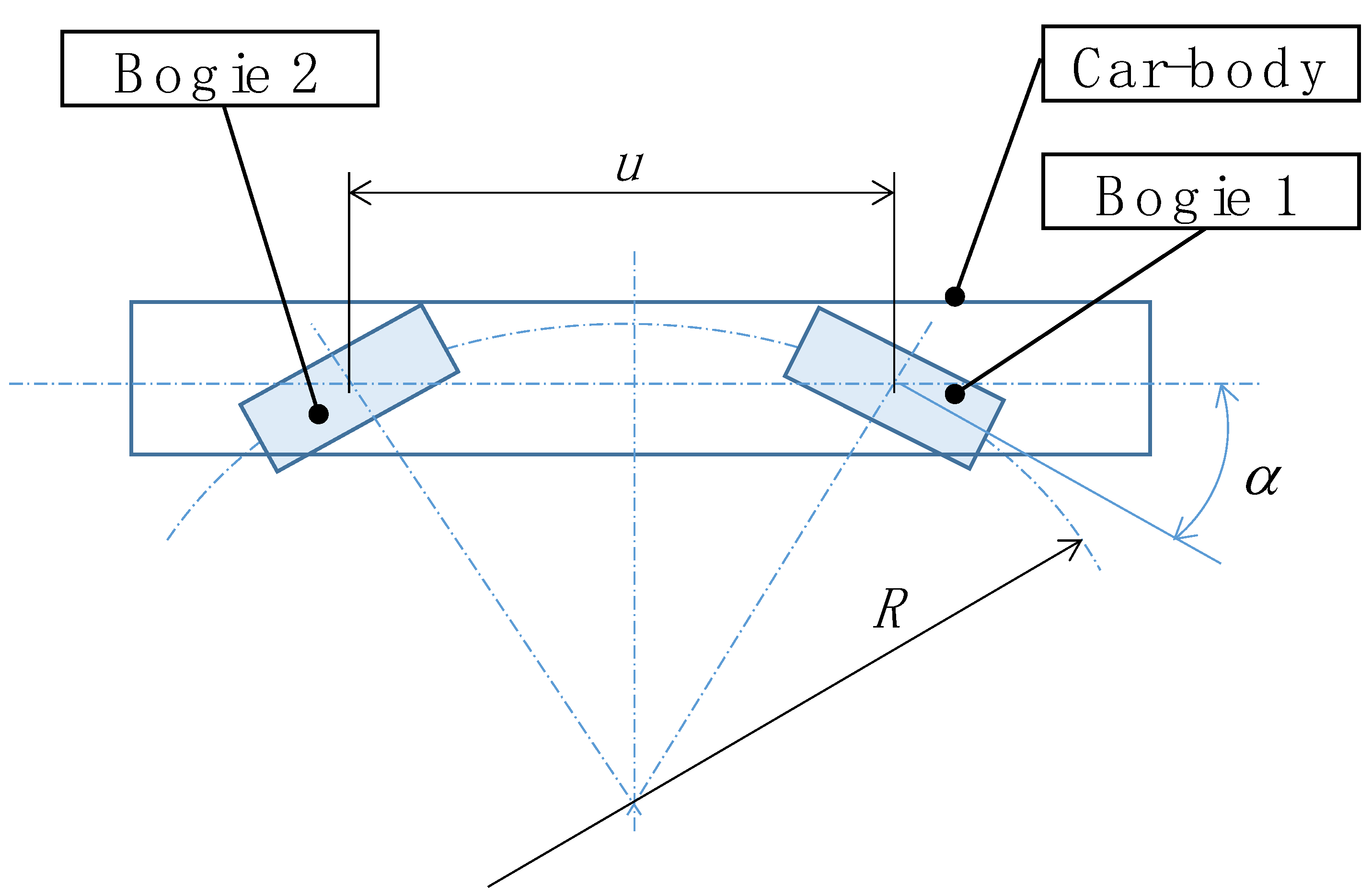
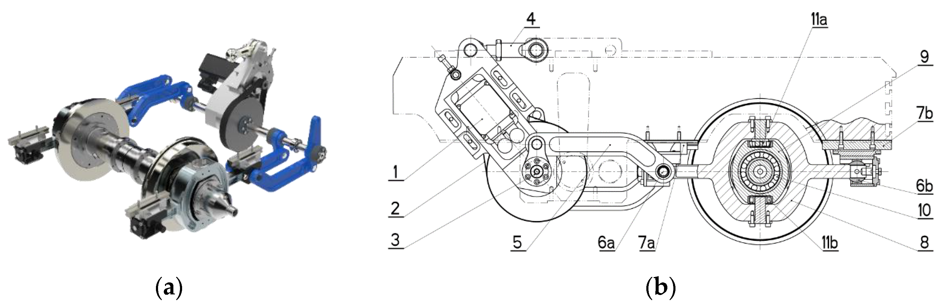
Due to the above reasons the estimation of the track radius by onboard sensors is proposed in this study. As an input for the tack radius estimation the rotation angle around vertical axis of the bogie towards the car body can be used. Assuming that the wheelsets follow the track centreline, the track curvature can be expressed by:
where
is track radius,
is track curvature,
is bogie distance, and
is angle of rotation of bogies towards the car body, see
Figure 6.
Equation (1) is fully valid only when the whole vehicle is in a curved track of a constant curvature.
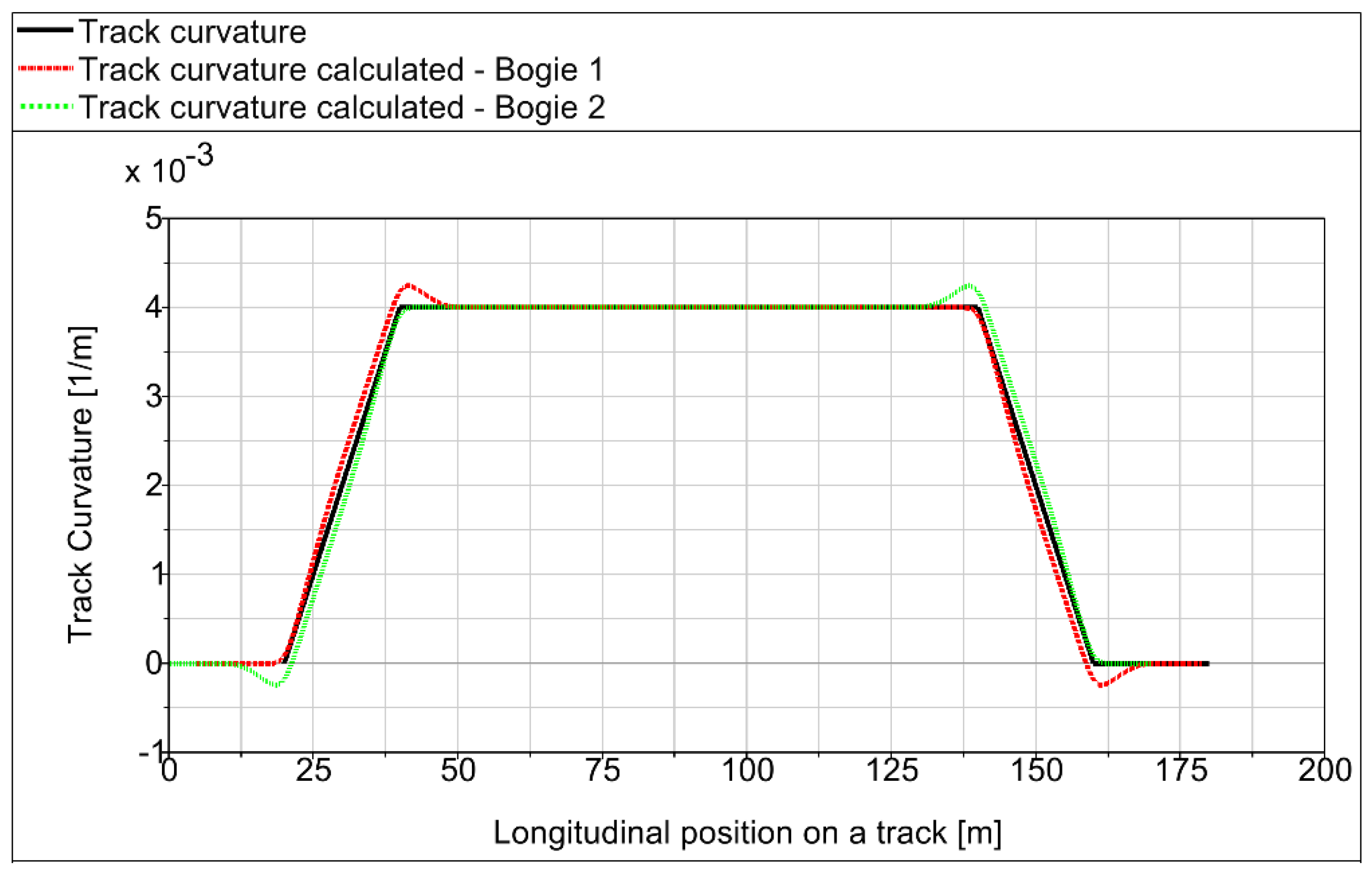
Figure 7 shows simulation results of a vehicle negotiation of a
track curve. It can be seen that in the transition track section, where the track curvature changes, the track curvature estimated by Equation (1) lags behind the actual track curvature on the leading bogie, whereas track curvature estimated on trailing bogie is ahead.
This phenomenon could be considerably eliminated by the method proposed in [
18]. The method utilizes not only the angle of bogie rotation towards the car body
, but also its derivative:
where
is time derivative of
and
is vehicle forward velocity.
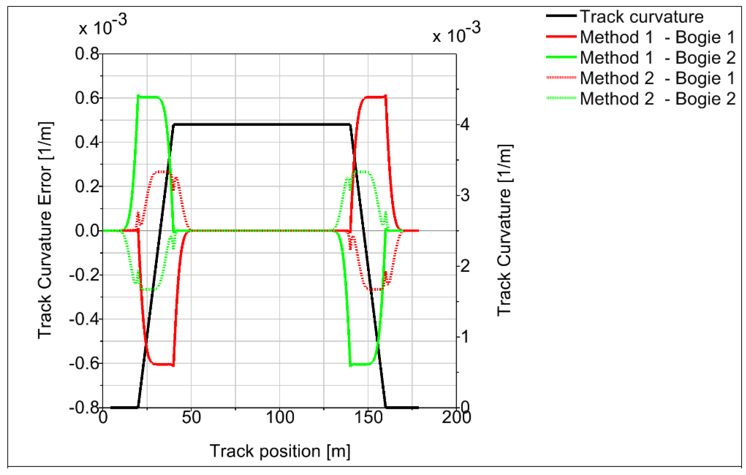
Figure 8 shows track curvature estimation by Equation (2) in
curve.
The curvature estimation leg is virtually eliminated, although small overshoots occur around points where the second derivative of track curvature changes. The error of the track curvature estimation for both calculation algorithms is plotted on
Figure 9. The algorithm according Equation (2) reduces the track estimation error in the transition track by more than 50% compared to the Equation (1). The track estimation error of Equation (2) in the transition track is less than 7%.
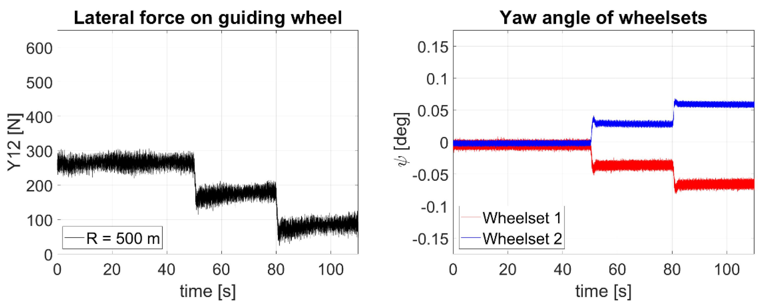
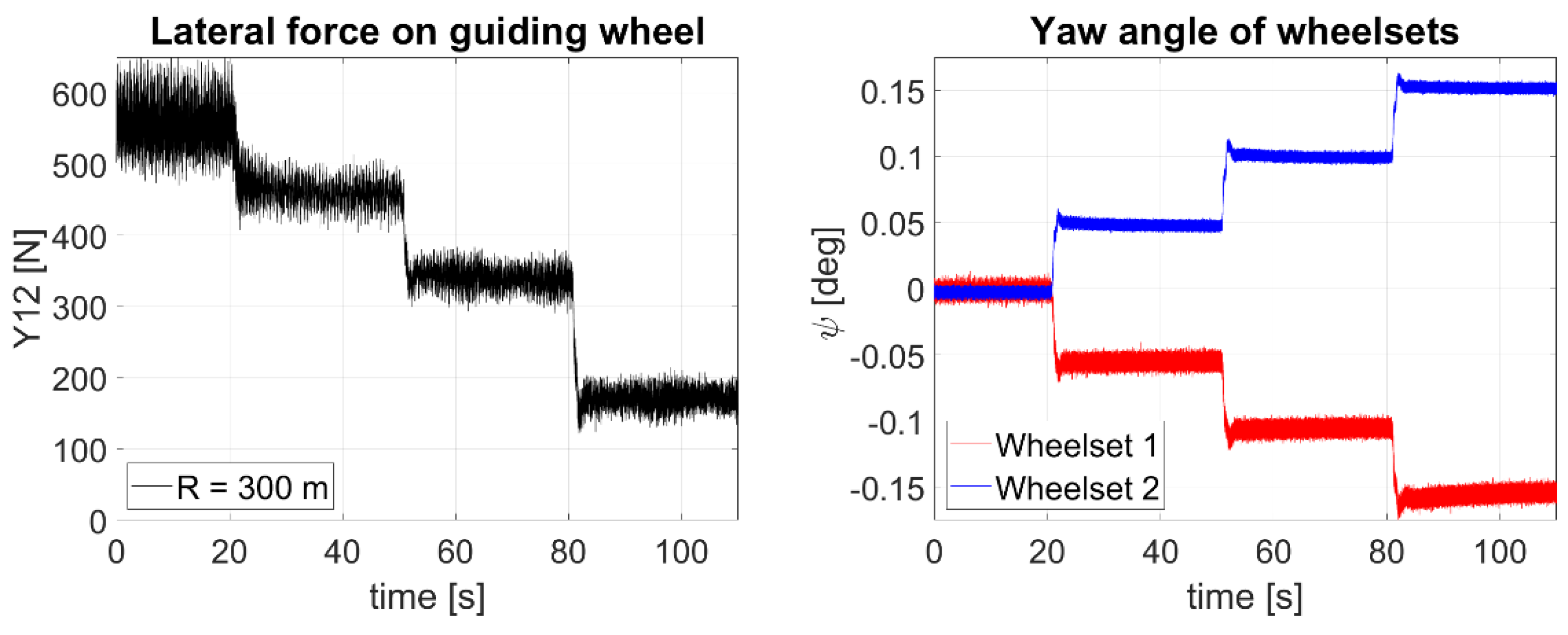
One problem is that the assumption of wheelsets that are perfectly aligned with the track centreline is not fully satisfied. A wheelset can move towards the track centreline in the lateral direction within the gauge clearance. Consequently, the angles of rotation of the first and second bogie differ, and vary in dependence of many parameters such as wheel and rail profiles, creep coefficients, value of unbalanced lateral acceleration, or torque caused by lateral deflection of flexi-coil springs. Typically, the leading bogie exhibits smaller angle and trailing bogie larger angle than is expected by ideal alignment of wheelsets and the track centre. The maximum deviation of the angles of rotation can be expressed by:
where
is gauge clearance and
is the wheelbase of the bogie. For the rail profile UIC 60, rail inclination 1:40, wheel profile S1002, and nominal values of wheelset and rail gauge is the gauge clearance
. Wheelbase of the locomotive under consideration
. According to Equation (3), it is then
. Thus, due to uncertain lateral position of wheelsets the error of estimated track curve curvature can reach tens of percent (see
Table 3).
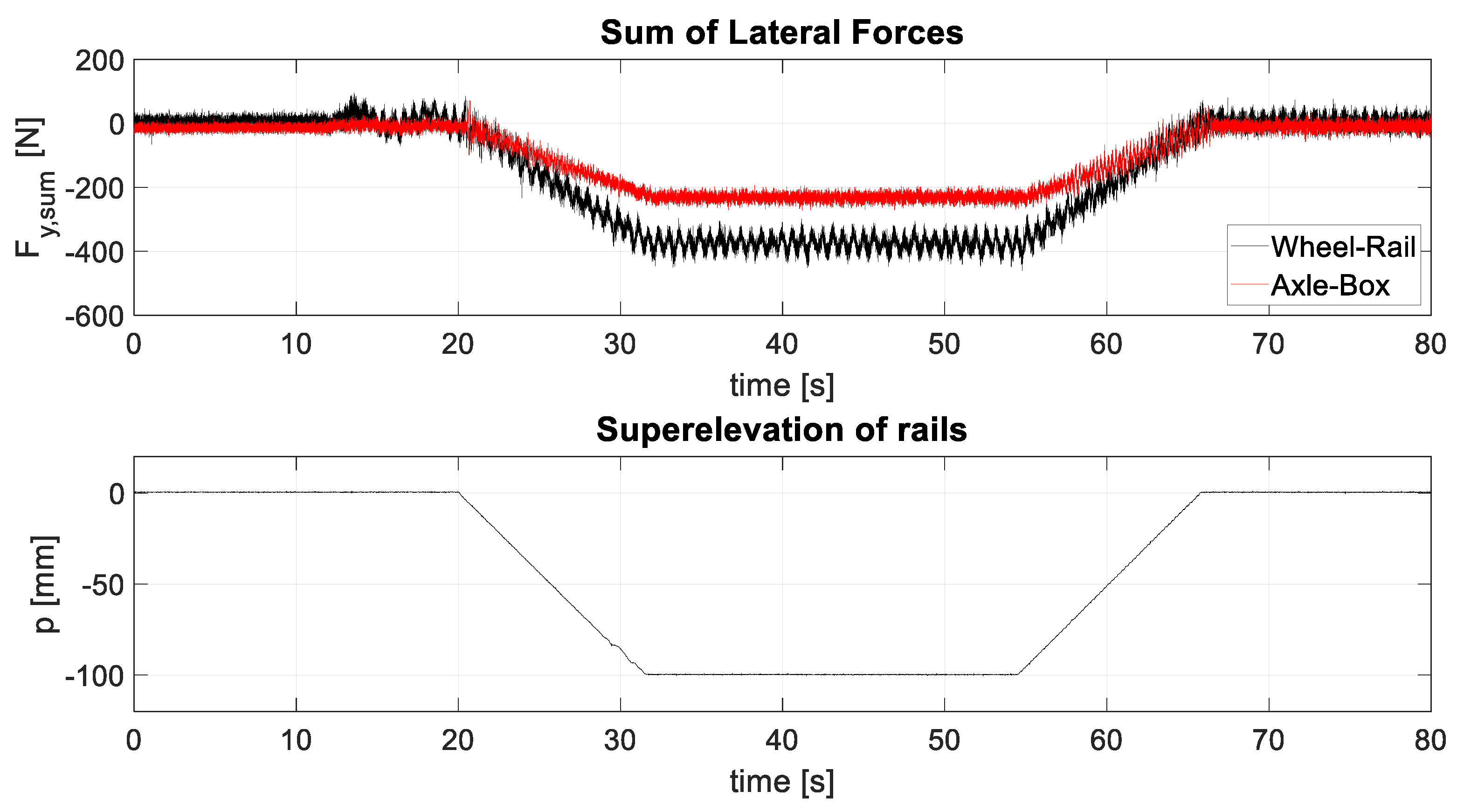
In order to determine the probable position of the wheelsets within the gauge clearance the set of simulations was performed. The simulation parameters are summarized in
Table 4, where
is superelevation of rails and
is the value of uncompensated lateral acceleration.
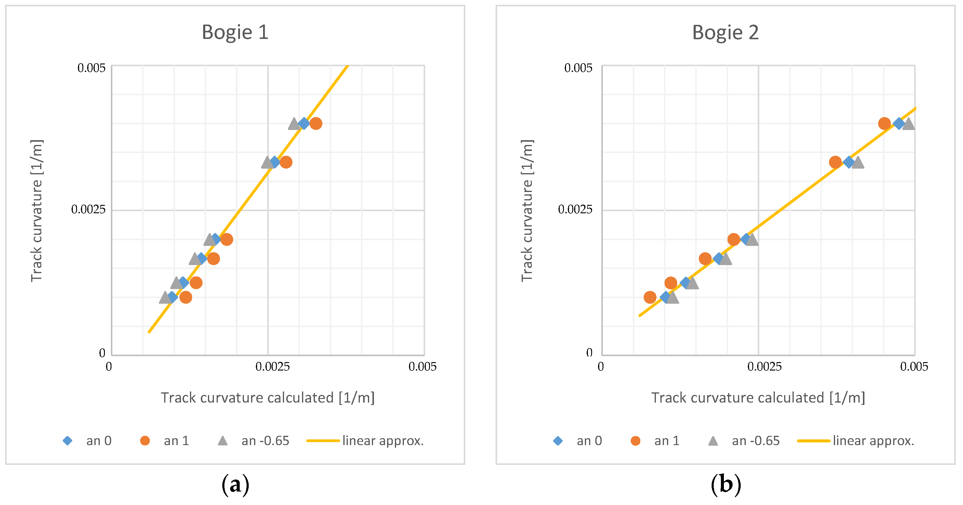
The simulations were performed for the ideal track without irregularities and friction coefficient 0.4. The quasistatic value of bogies rotation towards car body were observed. Based on the bogie rotations the track curvature was calculated using Formula (2) and compared to the real track curvature. The results are shown of
Figure 10.
The results confirm underestimation of track curvature on leading bogie and overestimation of track curvature on trailing bogie. This phenomenon is more significant for negative values of uncompensated lateral acceleration, i.e., in low speeds. In order to eliminate it, a linear approximation of relation between calculated and real track curvature was constructed. The approximation is shown on
Figure 10 by yellow curve and mathematically can be expressed by:
where
is real track curvature,
and
are track curvatures calculated on leading and trailing bogie, respectively, and
,
,
, and
are coefficients of the linear approximation.
Combining the relations Equations (2) and (4) the final relation for calculation of the track curvature is obtained:
Track curvatures obtained by Formula (5) for the set of 18 simulations are summarized in
Table 5.
The maximal error in track curvature calculation is around 25%. However, the maximal error values are obtained in large curve radiuses. The system of active wheelset steering is aimed especially for the small and very small radius curves, which radius is typically in the range from 250 m to 600 m. In this range, the error of track curvature calculation is under 14%.
The track conditions vary in time due to the wear, weather, rail pollution, and other factors that significantly influence the value of friction coefficient in the wheel-rail contacts. All above simulations were performed in dry rail conditions with friction coefficient 0.4. To assess the influence of the friction coefficient to track curvature estimation a set of simulations for friction coefficient 0.15 was completed. The results are summarised in
Table 6.
The results show that for the low value of friction coefficient, the precision of the track curvature calculation is decreased. The maximal error reaches 28% in large radius curves and 25% in small and very small radius curves. This relatively high error is obtained in runs with large positive uncompensated lateral acceleration, runs № 10 and 11.
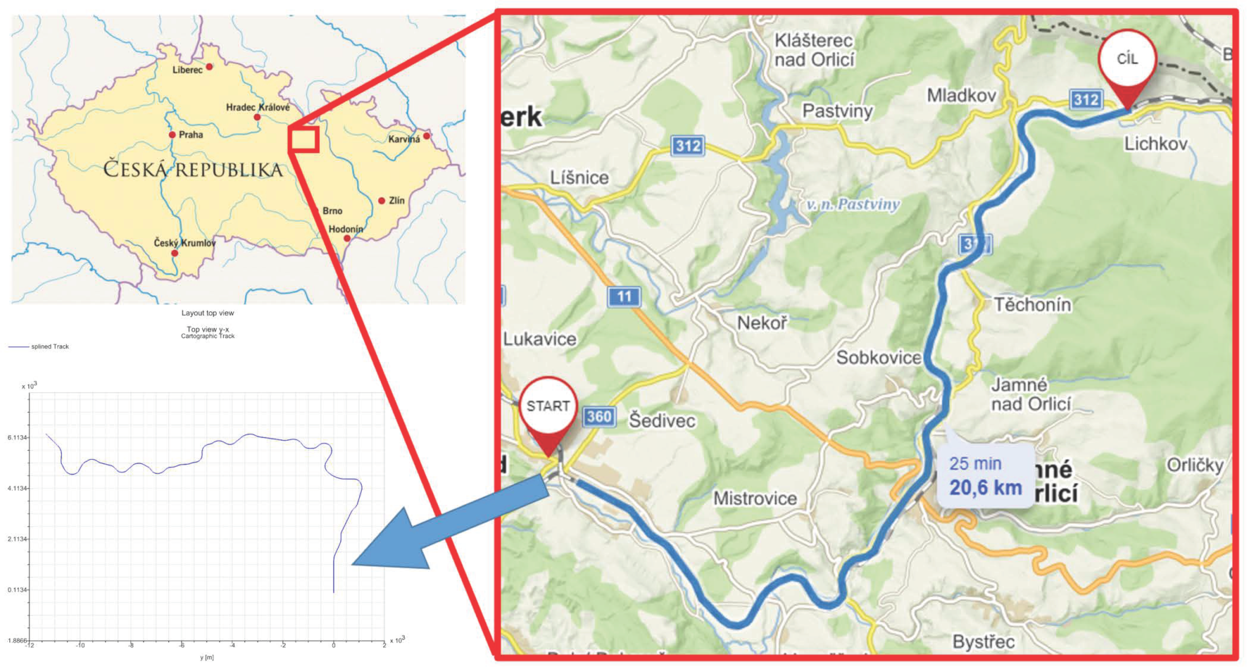
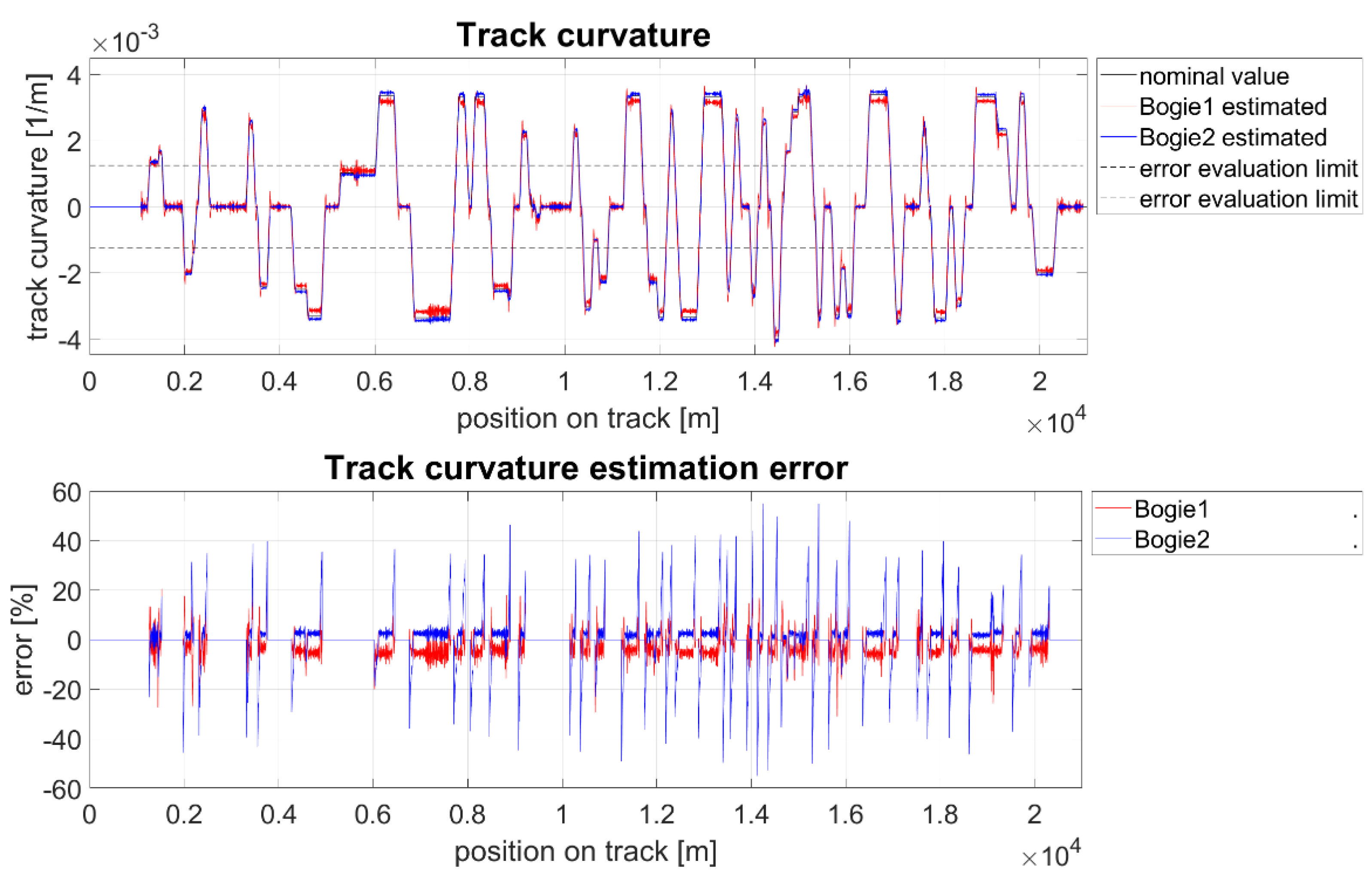
The section of the Letohrad–Lichkov line (
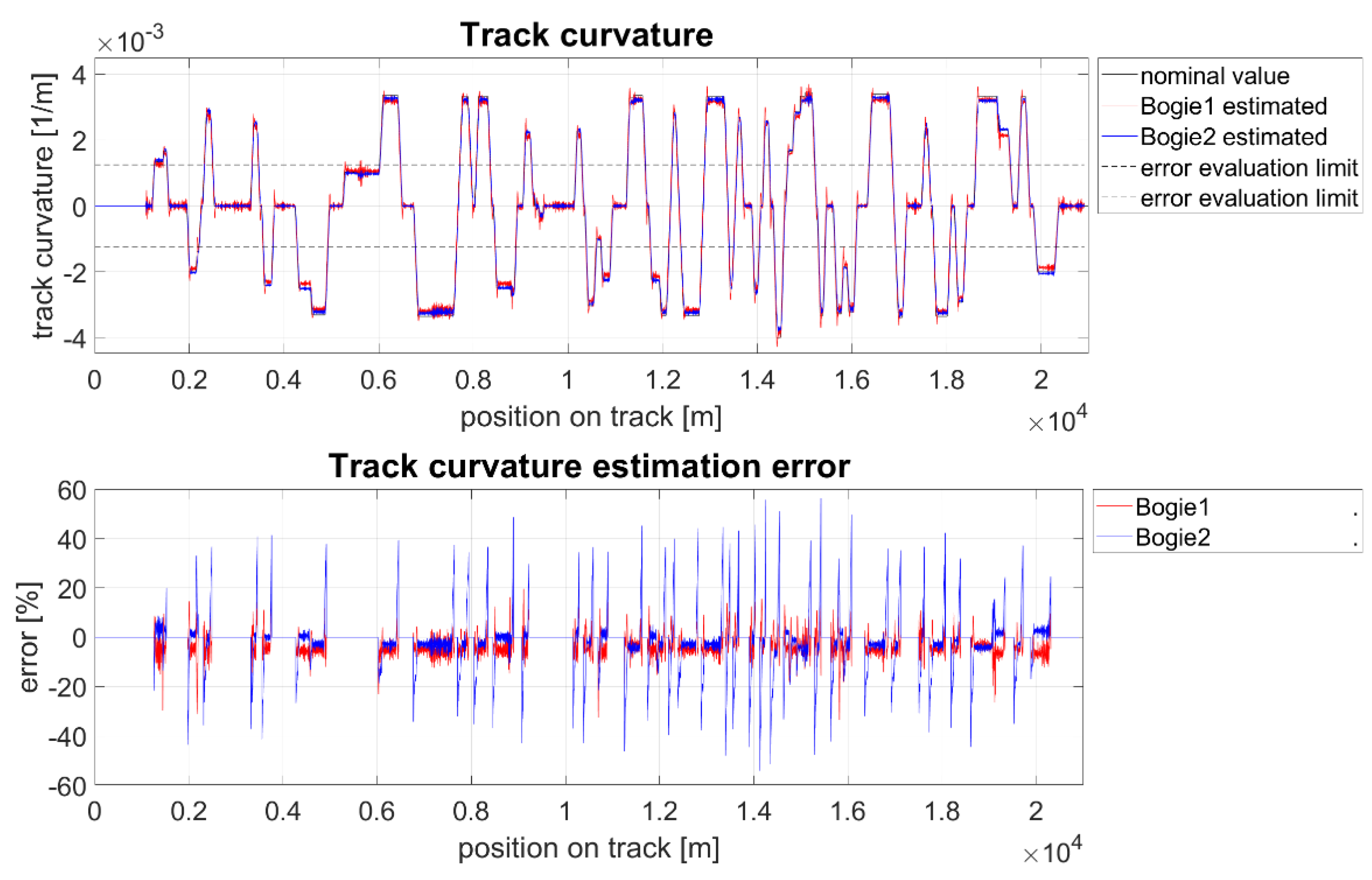
Figure 11) was chosen as the test track for assessing the behaviour of the proposed track curvature estimation algorithm. This track is characterized by a large number of consecutive curves and is also often used during test runs of new types of rail vehicles. The track was modelled including the measured track irregularities that were obtained by track geometry measurement.
The simulations were performed at the vehicle speed of 80 km/h for two values of the friction coefficient in wheel-rail contacts
f = 0.4 (
Figure 12) and
f = 0.15 (
Figure 13). The error between the estimated and the actual value of the track radius was evaluated for the both bogies in curves with an absolute value of track curvature greater than 0.00125 m
−1 which corresponds to track radiuses less than 800 m.
The simulations show a very good agreement between the calculated and the actual value of the track curvature. In constant radius curves, the error is less than 10% regardless of the friction coefficient. In transitions sections, the error on the rear bogie occasionally exceeds 50%. However, errors that exceed 20% occur only for a very short time. This phenomenon thus can be eliminated by signal filtering, or by track curvature estimation performed by measurement on leading bogie only and utilizing it for the wheelset steering controllers on both bogies.


