Abstract
During transients that occur in an electric network, large currents can flow and large electromagnetic torques can be developed in electric generators. Accurate calculation of currents and magnetic fields during transients is an important element in the optimal design of generators and network parts, as well as mechanical parts of machines and other torque transmission parts. This paper describes the modeling of a sudden three-phase short-circuit on a synchronous generator using the finite element method (FEM) and the dynamic model. The model for simulations that use the FEM was built in the MagNet software package, and the dynamic model is embedded in the MATLAB/Simulink software package. The dynamic simulation model of a part of a network with two identical generators, represented by equivalent parameters, was developed. The results obtained after the simulation of a sudden three-phase fault in the generators by both methods are presented, including three-phase voltages, three-phase currents, machine speeds, excitation voltages, and mechanical power. In particular, the short-circuit current in the phase with the highest peak value was analyzed to determine the accuracy of the equivalent parameters used in the dynamic model. Finally, the results of these two calculation methods are compared, and recommendations are presented for the application of different modeling methods.
1. Introduction
Transients are the time intervals that occur when a system is transiting from one steady state to another. Such a time interval can be understood as the time of adaptation by all system parameters to the new conditions in the network. Electromagnetic transients occur in the windings of electrical machines after a disturbance, the activation of a protective system, or the interaction between electrical machines and the network. The duration of transients is from milliseconds to seconds. Electromechanical transients refer to changes in speed and torques in the rotating parts of electrical machines and turbines. These transients are slower, and last from a second to a few seconds.
Understanding the details of transients is very important in the proper design of all parts of a power system, including synchronous generators, which are an integral part of a power system [1]. Early models for calculating parameters that occur during transients consisted of simple analytical expressions, included many simplifications, and were only used in some special cases. From a general model of electrical machines [2] that can be represented by equivalent circuits, dynamic models have been developed for certain types of electrical machines. These models consist of systems of differential equations that are solved numerically for given initial conditions, mainly in the time domain. The application of these systems became possible after computers reached a stage of development that provided the solutions in a relatively short time. Dynamic models have significantly increased the precision of the results. However, the accuracy of these models still depends on how precisely the parameters of the equivalent circuit are calculated. The parameters are still determined by analytical methods or measured on a built-in generator.
In these models, it is usually assumed that the parameters of the electrical machine are constant. The variability of the parameters is considered only in models that are more complex. The variability in parameters is mainly caused by saturation and by the shape of the air gap; the skin effect in conductors could also have a significant influence.
Nowadays, very sophisticated methods are used to calculate the parameters of electrical machines, including those in transient processes. These methods are based on numerical calculations in determining the electromagnetic field. Specialized software, such as the MagNet software package [3], was developed for such modeling using the finite element method (FEM), as presented here. The application of this software requires an approach that includes setting the electrical and magnetic characteristics of the materials from which the machine is made, building a solid model, and defining the conductors and their connections to the electrical circuits. Finally, it is necessary to define a finite element network, which can be a very time-consuming process.
The parameter estimation of a model synchronous generator is analyzed in [4,5,6,7,8]. A two-dimensional (2D) time-stepped FEM is used to model three-phase short-circuit test responses on large hydro generators [4]. The authors in [5] describe the application of a 2D model based on the Gaussian Modulated Sinusoidal Pulse (GMSP), validated by comparing the simulation results with the experimental data from a sudden three-phase short-circuit fault. The parameters for standard test procedures, such as the three-phase short-circuit test, have been implemented in time-stepping finite element software in [6] and validated by comparison with test results from the commissioning of a large hydropower generator. The rotor of a large turbo generator is modeled using the FEM with solid, hollow, and tapered elements in [7,8]. Different types of faults were simulated and analyzed in MATLAB: line-to-ground (L-G), line-to-line (L-L), three-phase (L-L-L), and loss of synchronism.
The most severe outcomes occurred during three-phase short-circuit testing. Ongoing research confirms that it is important to analyze generator parameters in the event of a sudden short-circuit. In [9], subtransient reactances and time constants are calculated by both analytical and finite-element methods, and applied to the classical circuit-theory simulation of a short-circuit fault. The terminal reactance parameters during the transient process were obtained using a 2D finite element analysis and validated by experimental results in [10]. Transient torques that appeared during faulty synchronization were observed in [11], and the physical quantities existing during faulty synchronization were compared with a three-phase sudden short-circuit state. From this comparison, the values of physical quantities that should be taken into account during the design of new hydro generators were selected. There are other interesting studies regarding transient modeling, such as [12], which deals with the transient modeling of thermoelectric modules as power generators and [13], which deals with the transient simulation of a combined system consisting of internal combustion engines and the organic Rankine cycle (ICE-ORC) designed in MATLAB/Simulink.
Many studies are engaged in the development of models that allow monitoring of generator behavior, especially during transients. In [14], the authors present the transverse magnetomotive force (m.m.f.) distribution model, and the calculated results are validated by the FEM and measurements. The multi-loop model of fractional pole-path ratio synchronous generators is proposed in [15], and comparisons of simulation results are again made by the FEM. The linear saturated lumped magnetic parametric model is developed to exhibit magnetic characteristics of a line-start permanent magnet synchronous motor, as proposed in [16]. The evaluation of analytical model validity is verified using a 2D FEM. In [17], the field-circuit coupled finite-element method is applied to predict the performance of an induction motor by solving the nonlinear time-stepping finite-element equations, coupled with circuit equations and mechanical motion equations. The research described in [18] is focused on the transient analysis of the electromagnetic and temperature fields on tubular hydro-generators during short-circuit faults. Testing and fine-tuning of the developed dynamic mathematical model of the hydropower plant, for research into the dynamic conditions of a transmission power system, are described in [19].
In the models presented here, the researchers successfully solved the problem of transients, but mostly in isolated cases of electrical machines on a network. However, if the impact on the wider parts of a power system, with all installed elements, is to be considered, then each element of the system must be presented with equivalent parameters. Then, the transients are solved by applying a system of differential equations, for which special software packages have been developed. Such a methodology is very practical and fast, but the accuracy of the obtained results depends on the accuracy of the equivalent parameters. The FEM is the most suitable method for calculating equivalent parameters, because testing procedures for extracting equivalent parameters often cannot be performed in real conditions. The research presented here refers to the methodology for verifying the accuracy of a fast simulation method by comparison with a more accurate method.
In this paper, results are presented for the simulation of a sudden three-phase short-circuit of a hydro generator, using the FEM for the calculation of the model’s magnetic field, which corresponds to an actual state. By using the FEM to calculate the magnetic field in electrical machines, it is possible to determine the actual values of electrical parameters, as this research indicates. The electromagnetic transients are also analyzed by simulating a three-phase short-circuit at the generator terminals on a simulation model that uses dynamic models of elements, such as actual hydropower plants connected to the distribution network.
The aim of this research was to determine deviations in the values of electrical parameters when using the dynamic simulation model, according to accurate calculations with the factory values of the synchronous generator. Comparing the simulation results obtained by these methods for a sudden three-phase short-circuit, a fine adjustment of the dynamic model parameters could be made to reduce these deviations. After such calibration of the dynamic model during the analysis of a particular event, the model can be used to analyze other disturbances in the network, as well as to analyze transients in other parts of the network in case of failure in the synchronous generator whose model is calibrated.
By analyzing the impact of interference in one part of the power system on other network elements, an appropriate selection of protective devices can be carried out, and the existing elements can be dimensioned to reduce the adverse impact of interference on their operation. Thereupon, the possibilities of applying different simulation models of the power network for transients analysis could be verified by the methodology presented here, which is the main contribution of this paper. Furthermore, the time dependence of the generator currents and voltages is presented, as well as the obtained results for rotational speeds, excitation voltages, and mechanical powers.
This paper is organized as follows: after the main parameters of the analyzed generator are presented, the calculation of the sudden three-phase short-circuit using the FEM is described; then, a description of a system of differential equations is used to calculate the transients in a dynamic model; this algorithm is built into the MATLAB software and used in the dynamic simulation model presented in this paper; a model of the network used for the simulation in the MATLAB software is presented in the next section; an overview of the obtained results related to current densities and magnetic field at characteristic moments of the transition is then provided, as well as the results obtained via a simulation model; a comparison of the calculation results of both methods is provided; and finally, the most important conclusions are summarized.
2. Modeling Methods for Transients Calculation
The calculation of the sudden three-phase short-circuit was performed on the synchronous hydro generator model with the following nominal data: power 30,000 KVA, voltage 10,500 V, current 1650 A, power factor 0.9, frequency 50 Hz, pole number 48, and rotation speed 125.
2.1. Modeling of a Sudden Three-Phase Short-Circuit Using the FEM
In order to conduct the FEM calculations, some preconditions needed to be introduced:
- all of the coils in windings have equal numbers of conductors and therefore equal resistance; windings are placed symmetrically on poles, enabling the analysis of one repeating segment of the generator;
- the ratio of the core length and the end winding length of the generator is 3.2, and allows the 2D model to be applicable;
- the influence of the skin effect, which can appear in excitation or in armature winding conductors, is neglected;
- the stray current and the eddy current are excluded because the electric conductivity of iron can also be neglected;
- embedded materials are isotropic, the hysteresis loop is neglected, and the iron permeability depends on the magnetic field strength;
- the rotor speed variations throughout the transients, due to high inertia of mass, are also neglected; and
- the sources used to feed the windings are assumed to be perfect.
These introduced assumptions significantly simplify the calculation. Therefore, although they have a certain influence on the obtained results, this calculation method gives the most accurate possible results because the original factory data on the dimensions, material properties, and other characteristics of all parts of the machine are used.
Figure 1 shows a solid model of 8 poles of the hydro generator using the previously presented software [3]. As there are 306 slots on a 48-pole generator, the segment for the model is chosen so that the symmetry is repeated after each part.
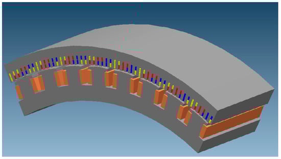
The model includes stator and rotor. Stator is made of non-skewed slots with three-phase winding conductors in a laminated core.
Rotor poles are mounted on a steel hub and made of steel laminations. Excitation winding coils are placed around the poles, and they are comprised of copper wires. Five holes are in the pole shoes, where round copper bars are inserted, creating the damping winding. Damper winding slots are closed.
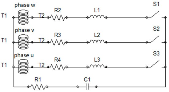
The windings of armature are coupled in Star (Y) without grounding the neutral point. Resistance and inductance representing the end windings are connected into the series with each phase. Because the end windings are in the air, these parameters can be assumed to be constant. In the path between the neutral point and the beginning of the phase there is capacitance and resistance, which represents the capacitances of the windings to the ground. Into the series with capacitance a small resistance is connected (Figure 2).
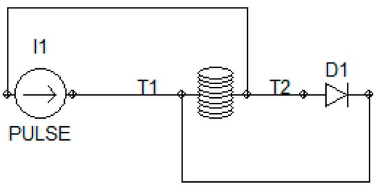
The excitation winding is connected to a current source, to which a diode is connected in parallel. The diode represents the branches of the rectifier bridge located on the output from the source that supplies the excitation winding and prevents overvoltage in the excitation circuit, allowing a positive current component to flow through it (Figure 3).
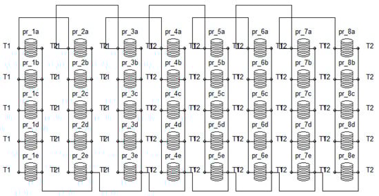
Damper winding is short-circuited at the ends of the bars by copper segments of negligible resistance (Figure 4).
A 2D FEM solver that considers the motion of the rotor must be applied to calculate the sudden short-circuit. The field can be solved with the equations presented in (1):
where
- is the electric field strength in the conductors,
- is the lux density,
- is the magnetic field strength,
- is thecurrent density,
- C is the curve bounding the surface S,
- S is the plane in which the field is calculated, and
- is the unit vector normal to surface S.
2.2. Sudden Short-Circuit by a Dynamic Model
The node-voltage matrix Equation (4) is used to determine electromagnetic events in windings of the machine [1]:
where
- [U] is the matrix of voltage,
- [i] is the matrix of current,
- [R] is thematrix of resistance,
- [L] is the matrix of inductance,
- ωel is the electric angle velocity of rotor, and
- γ is the electric angle between the axis of stator phase “a” and the d-axis of rotor.
The practice is to make the transformations of variables in the two-phase rotors “dq0” coordinate system instead of in the primary three-phase “abc” system, in order to eliminate the mutual inductance connection placed between the windings with axes that are not perpendicular to each other, as well as the interrelation of inductance on the angular position of the rotor. The transformation matrices used for the substitution of a three-phase electrical machine to a two-axis model are elaborated upon in (2). In order to prepare the system for suitability with computer modeling, the matrix in Equation (4) is disassembled into a system of differential equations. That system introduces current substitution and mutual magnetic fluxes. However, the zero component of the current cannot flow in the armature winding, thus the zero variables are not present in the next system of equations:
where
- Ψd is the magnetic flux in armature winding in d-axis,
- Ψf is the magnetic flux in excitation winding,
- ΨD is the magnetic flux in damping winding in d-axis,
- Ψq is the magnetic flux in armature winding in q-axis,
- ΨQ is the magnetic flux in damping winding in q-axis,
- ud is the transformed armature winding in d-axis,
- uf is the excitation voltage,
- uq is thetransformed armature winding in q-axis,
- kd is the linkage factor of armature winding in d-axis,
- kf is the linkage factor of excitation winding,
- kD is the linkage factor of damping winding in d-axis,
- kq is the linkage factor of armature winding in q-axis,
- kQ is the linkage factor of damping winding in q-axis,
- is the transient inductance of damping and excitation windings,
- is the transient inductance of armature and damping windings,
- is the transient inductance of excitation and damping windings,
- is the transient inductance of armature and excitation windings,
- is the transient inductance of excitation and armature windings,
- is the transient inductance of damping and armature windings,
- is the subtransient inductance of armature winding in d-axis,
- is the subtransient inductance of excitation winding,
- is the subtransient inductance of damping winding in d-axis,
- is the subtransient inductance of armature winding in q-axis,
- is the subtransient inductance of damping winding in q-axis,
- is the subtransient time constant of the armature winding at short-circuit in d-axis,
- is the subtransient time constant of the armature winding at short-circuit in q-axis,
- is the subtransient time constant of the damping winding at short-circuit in d-axis,
- is the subtransient time constant of the damping winding at short-circuit in q-axis,
- is the subtransient time constant of the excitation winding at short-circuit, and
- H is the inertia constant.
The presented algorithm is suitable for simulation of transients that are symmetric, such as a three-phase short-circuit, fault synchronization, or asynchronous start-up. In case of asymmetric states in the network, such as a two-phase short-circuit, other assumptions should be introduced.
In the case of a two-phase short-circuit in the network, the system can be used as determined by the corresponding values of the phase voltages, known as direct and inverse components. In the case of a two-phase short-circuit without a network, on an open phase terminal the system is simulated by adding a fictitious resistance to the open phase and subsequently performing the transformations described in [2].
The algorithm for calculating the initial inductances, the transient inductances, the initial time constants, and all linkage factors, is described in [2].
Differential Equations (5)–(9) are used to calculate the linked fluxes, and (10) presents the equation of motion. Figure 5 and Figure 6 present the equivalent diagrams for transverse and longitudinal axes, as the result of this system of equations.
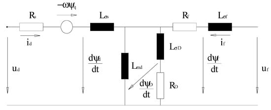
Figure 5.
Synchronous machine equivalent diagram for d-axis adapted with permission from ref. [1]. Copyright 2021 IEEE.
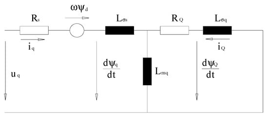
Figure 6.
Synchronous machine equivalent diagram for q-axis adapted with permission from ref. [1]. Copyright 2021 IEEE.
The following equations have been used to calculate initial conditions:
Under the no-load operation, the only current flowing through the generator is the excitation current if0, which influences only the magnetic fluxes in d-axis. Therefore, the initial values of parameters in the q-axis equal zero. In the windings of armature and damping, the magnetic flux in the p. u. system is . The magnetic flux in the winding of excitation is slightly higher, because it contains the component of leakage flux between the poles.
3. Transient Analysis Using a Dynamic Simulation Model
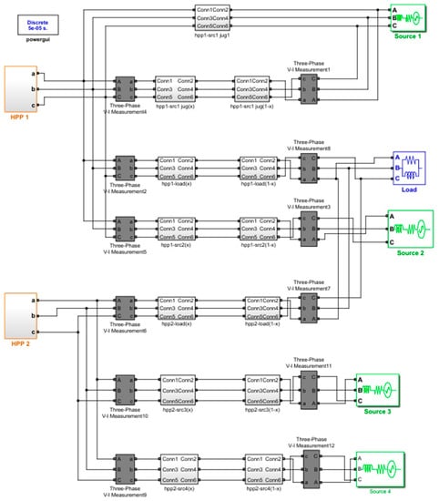
Electromagnetic transients were simulated on the model built in the MATLAB/Simulink/Simscape electrical software environment shown in Figure 7. The model is based on a real power network (a part of the Slovenian transmission system) and consists of several subsystems: hydropower plants HPP 1 and HPP 2, transmission lines, three-phase V-I measurements at the beginning and the end of each transmission line, three-phase sources, and a three-phase parallel RLC load. A transmission line was modeled by RL elements for each phase. The three voltage sources were connected in Y to an internal floating neutral. The load flow tool, which uses the Newton-Raphson method to provide a robust and fast convergence solution, was used to perform the load flow and for the initialization of three-phase networks and machines, so that the simulation starts in a steady state. For HPP 1, simulations were performed at no-load conditions. The generator type of the voltage sources was modeled to allow for control of the magnitude and the phase angle of the terminal voltage; the active power P and the reactive power Q were adjusted to allow the calculation to converge. The load type was set to constant PQ, i.e., active power and reactive power were kept constant and equal to the specified values, and the voltage angle was adjusted. The generator type of the synchronous machine was PV, i.e., active power and voltage magnitude were specified, and the voltage angle and the reactive power were adjusted. As a method to solve a circuit, discretization of the electrical system at the fixed time-step of 50 µs was chosen.
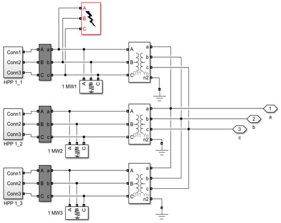
The influence of the short-circuit on the current-voltage conditions of the observed network was analyzed by simulating a three-phase short-circuit at the generator terminals in HPP 1, as shown in Figure 8. The three-phase fault block implemented a three-phase circuit breaker, where the opening and closing times were controlled.
The values of the parameters used for the synchronous generator model were:
- d-axis synchronous reactance Xd = 1.06 p. u.,
- d-axis transient reactance Xd′ = 0.28 p. u.,
- d-axis subtransient reactance Xd″ = 0.192 p. u.,
- q-axis synchronous reactance Xq = 0.61 p. u.,
- q-axis subtransient reactance Xq″ = 0.176 p. u.,
- leakage reactance Xl = 0.14 p. u.,
- d-axis transient short-circuit time constant Td′ = 1.56 s,
- d-axis subtransient short-circuit time constant Td″ = 0.05 s,
- q-axis subtransient open-circuit Tqo″ = 0.09 s,
- inertia constant H = 3.2 s,
- friction factor F = 0, and
- stator resistance Rs = 0.0161 p. u.
4. Results and Discussion
This section provides an overview of the results of the calculations made using different methods, and a comparison and discussion of the obtained values for the observed hydro generator.
4.1. The Results of the FEM Calculation Method
The calculation was performed in the time from 0 to 0.1 s, i.e., which corresponds to five periods of the fundamental harmonic. The rotor speed was constant and equal to the nominal value. Figure 9 shows the magnetic field as the result of the FEM at the beginning of the transient, and in Figure 10 the magnetic field is shown after half of the period, when the current at one phase reaches its maximum.
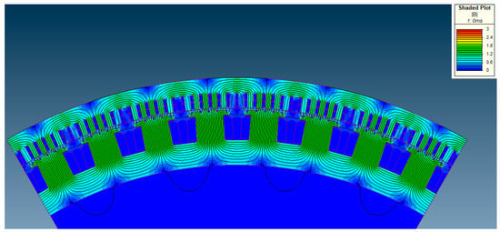
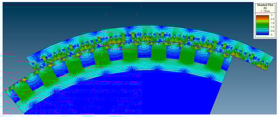
Figure 11 shows the steady state magnetic field. In the moment of the half period after the start of a short-circuit, the magnetic field of the stator is the same as at no load but does not penetrate the rotor. In addition, the magnetic field of the rotor is the same as at the initial moment. In the steady state, the magnetic field is much smaller, but its distribution is similar to that at no load. The magnetic field penetrates the rotor. The results are as expected and in accordance with well-known theory.
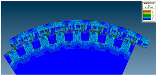
The magnetic induction absolute value at each point in the model can be read in the legend in the upper right corner of each Figure.
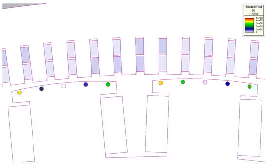
The current densities in the phase windings and damper winding bars, half the time after the beginning of the short-circuit, are shown in Figure 12. The current densities are of different amounts and their absolute value is visible in the logarithmic scale located in the upper right corner of Figure 12. The current density in an individual bar depends on its position on the pole shoe, and on the current position of the pole relative to the stator. The current densities are higher in the bars placed at the ends of the pole, while the current density decreases in the bars placed closer to the middle of the pole. The reason for that difference is that the current loop formed by the end bars has the largest surface through which the magnetic flux passes. The symmetry in damper bar currents is repeated for each generator segment.
The currents in the damping bars affect the saturation of the core above the slot. Figure 13 shows that the highest saturation is just above the slots where the current density is highest. The peak value of the sudden short-circuit current depends on the magnetic flux component that closes just above the slot. In addition, harmonics in the phase currents may also occur.
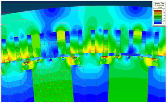
Figure 14 shows the results for phase currents obtained by the FEM calculation. The current in phase “w” reaches a maximum of 27.8 kA, as the initial moment is selected when the voltage in that phase is equal to zero.
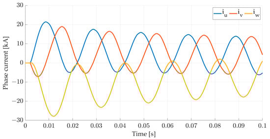
In all the currents, a distortion of sinusoidal shape is present because of calculations with materials that have a nonlinear magnetization characteristic. The material used for the poles and the stator core is dynamo sheet M330-50A. It is known that the short-circuit current is mostly affected by the initial reactances, and that they depend on the shape of the damper winding slot. In the case of this generator, these slots are closed, and the reactance is dependent on the current flowing through the damper bars. The saturation of the magnetic paths above the damping winding, and thus the phase current of the generator, depends on the current through the damper bars. This impact can only be seen by the FEM in the time domain calculation.
In addition to the harmonics in the phase currents, DC components are disclosed, which decrease with the subtransient and transient time constants.
4.2. The Results of Three-Phase Fault on the Generator in the Dynamic Simulation Model
Figure 15 and Figure 16 show the results obtained for the observed two power plants in real power networks HPP 1 and HPP 2, after the simulation of the three-phase fault at the generator terminals in HPP 1. The fault is initiated at 0 s, which is the moment when the voltage in one phase is equal to zero. In Figure 15, it can be seen that the currents of all three phases increase. It can also be observed that there is a voltage drop in all three phases (the voltage is 0) in HPP 1. In HPP 2, there is almost no voltage drop and a small increase in currents can be noticed. Short-circuit currents are higher in HPP 1 because it is electrically closer to the fault location.
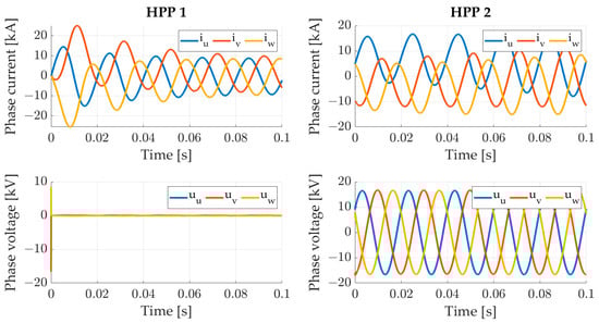
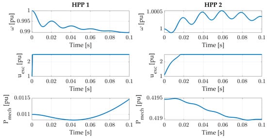
Figure 16 shows the machine speed, excitation voltage, and mechanical power for the two observed power plants, HPP 1 and HPP 2, when the three-phase fault occurs in HPP 1 at the generator terminals. Speed value was set at 1 p. u., which corresponds to the synchronous speed in the steady state, and a minimal change in speed is visible. In response to increased excitation voltage in HPP 2, transients occur as the behavior approaches the new steady state. Voltage goes to 2.5 p. u., which is the regulator output limit; 1 p. u. corresponds to the excitation voltage at no load. The variation of the excitation voltage caused by the voltage regulator does not significantly influence the values of the electrical and mechanical parameters of the generator where the short-circuit occurred, but does affect the parameters that occur on the generator that is farther from the fault location. Due to the function of the voltage regulator on the generator that is farther away from the fault location, the phase voltages do not show a significant deviation from the nominal value, and the asymmetry of the phase currents is reduced.
In the dynamic simulation model, the generator no-load characteristic is considered, and the calculation of the transient with and without the influence of saturation can be performed. Since the machine is low-saturated at the rated voltage, i.e., the saturation factor of the magnetic circuit is only 1.05, no significant differences were observed between the currents obtained by the dynamic simulation model, with or without taking the magnetic saturation into account. The presented values used for comparison of the two analyzed methods shown in Figure 17 are with saturation.
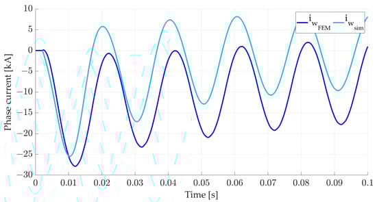
Figure 17.
The comparison of phase current “w” obtained by the FEM calculation and by the dynamic model.
In Figure 17, the currents in phase “w” obtained by the FEM calculation with the dynamic model are presented. The peak value of current obtained by the dynamic model is 25.48 kA; with the FEM, it is 27.87 kA, which is a deviation of 9.38%. This is the current of the phase in which the voltage was zero at the time of the short-circuit.
Since the actual sudden short-circuit current can only be determined by measuring on a produced machine in real conditions, its exact amount is not known. The dynamic model uses the parameters of the equivalent diagram, obtained by measuring with standard methods that are usually performed at low voltages on such large machines. Those conditions cause the obtained reactances to always be higher than the actual ones. Therefore, the peak value of the sudden short-circuit current obtained by the dynamic model is less than that obtained by the FEM.
There is a small phase shift between the waveforms due to a change in the rotational speed considered in the dynamic simulation model, while in the FEM it is calculated with a constant speed during the transient.
The FEM calculation takes into account the actual form of the produced machine as well as the actual conditions under which the transients occur. The actual state of saturation can only be obtained by the FEM. The solution for the magnetic field shows high saturations in the region above the slot of the damping winding, and it is obvious that the actual initial reactance Xd″ is less than that set in the dynamic model. This is the main reason that the peak value of the short-circuit current obtained by the FEM is higher than that obtained by the dynamic model. The results obtained by different methods in all three phases could be very similar if the parameters of the equivalent diagram needed for the dynamic model could be determined properly. In this example, the performance of the FEM calculation is recommended, followed by elaboration of the results in the same way as is done when testing the finished generator, in order to determine the standard generator reactances in the longitudinal axis and the time constants. This procedure demonstrates the proper way to apply these methods for the analysis of transients during a three-phase short-circuit on a synchronous hydro generator, and on the other parts of the system.
5. Conclusions
Power system disturbances are becoming more frequent and faster due to continuous decreases in inertia. Therefore, it is important to have accurate models of all power system elements, especially synchronous generators, which are last-standing inertia contributors. This paper proposes a methodology for accurate fine adjustment of the dynamic model of synchronous generators by applying a combination of two independent algorithms.
In calculating the transients in synchronous generators and the network, it is possible to apply a simulation model or the FEM to an actual generator model. The application of the simulation model is simpler and faster, but it requires accurate knowledge of the parameters of the generator-equivalent diagram. These parameters are not constant, due to the nonlinear magnetizing characteristic of the core from which the magnetic circuit is made, and also due to the complex form of the magnetic circuit of the generator. Calculations using the FEM require knowledge of the actual form of the machine and all the built-in materials. However, these calculations provide results that are more complex and require significantly more time.
To obtain more accurate results of transients using a standard simulation model, it is recommended that calculations be performed on the model by the FEM for a certain system, and that the parameters be subsequently corrected in the equivalent diagram in the simulation model. Such a finely adjusted simulation model will provide more precise results in the analysis of other possible disturbances of the observed system.
Author Contributions
Conceptualization, D.S. and B.T.; methodology, B.T. and A.Š.; validation, D.S. and J.N.; formal analysis, B.T. and J.N.; resources, A.Š.; data curation, B.T.; software, B.T. and A.Š.; writing—original draft preparation, B.T. and A.Š.; writing—review and editing, D.S.; visualization, D.S., B.T. and A.Š.; supervision, D.S. All authors have read and agreed to the published version of the manuscript.
Funding
This research received no external funding.
Data Availability Statement
Data is contained within the article.
Conflicts of Interest
The authors declare no conflict of interest.
References
- Tomicic, B.; Stih, Z.; Car, S. The Modelling of Transients in Synchronous Generators for Wind Turbine. In Proceedings of the 2007 International Conference on Clean Electrical Power, Capri, Italy, 21–23 May 2007; pp. 591–597. [Google Scholar] [CrossRef]
- Krause, P.C. Analysis of Electric Machinery; McGraw Hill, Inc.: New York, NY, USA, 1986. [Google Scholar]
- Magnet, Version 6.5; “Tutorials”; Infolytica Corporation: Montreal, QC, Canada, 2000.
- Wamkeue, R.; Kamwa, I.; Chacha, M. Line-to-line short-circuit-based finite-element performance and parameter predictions of large hydrogenerators. IEEE Trans. Energy Convers. 2003, 18, 370–378. [Google Scholar] [CrossRef]
- Hernandez, C.; Cisneros-Gonzalez, M.; Arjona, M.A. A Gaussian Modulated Sinusoidal Pulse for Circuit-Parameter Estimation of a Synchronous Generator Using a 2D-FE Field Model. Appl. Comput. Electromagn. Soc. J. 2012, 27, 734–741. [Google Scholar] [CrossRef]
- Lidenholm, J.; Lundin, U. Estimation of Hydropower Generator Parameters through Field Simulations of Standard Tests. IEEE Trans. Energy Convers. 2010, 25, 931–939. [Google Scholar] [CrossRef]
- Kumar, T.; Kumar, R.; Jain, S.C. Finite Element Modeling of Big Turbo-Generator Rotor Vibrations using Newmark-beta Integration Method. IOP Conf. Ser. Mater. Sci. Eng. 2020, 876, 012004. [Google Scholar] [CrossRef]
- Kumar, T.; Kumar, R.; Jain, S.C. Numerical Investigation of Semi-active Torsional Vibration Control of Heavy Turbo-generator Rotor using Magnetorheological Fluid Dampers. J. Vib. Eng. Technol. 2021, 9, 967–981. [Google Scholar] [CrossRef]
- Klontz, K.W.; Miller, T.J.E.; McGilp, M.I.; Karmaker, H.; Zhong, P. Short-Circuit Analysis of Permanent-Magnet Generators. IEEE Trans. Ind. Appl. 2011, 47, 1670–1680. [Google Scholar] [CrossRef]
- Xiao, Y.; Zhou, L.; Wang, J.; Yang, R. Finite Element Computation of Transient Parameters of a Salient-Pole Synchronous Machine. Energies 2017, 10, 1015. [Google Scholar] [CrossRef] [Green Version]
- Gozdowiak, A. Faulty Synchronization of Salient Pole Synchronous Hydro Generator. Energies 2020, 13, 5491. [Google Scholar] [CrossRef]
- Marjanović, M.; Prijić, A.; Randjelović, B.; Prijić, Z. A Transient Modeling of the Thermoelectric Generators for Application in Wireless Sensor Network Nodes. Electronics 2020, 9, 1015. [Google Scholar] [CrossRef]
- Liu, T.; Wang, E.; Meng, F.; Zhang, F.; Zhao, C.; Zhang, H.; Zhao, R. Operation Characteristics and Transient Simulation of an ICE-ORC Combined System. Appl. Sci. 2020, 9, 1639. [Google Scholar] [CrossRef] [Green Version]
- Gang, L.; Dihui, Z.; Tong, Z. Influences on performance in 3D analysis of linear induction motors with different transverse m.m.f. models in winding end-regions. IET Electr. Power Appl. 2017, 11, 1424–1431. [Google Scholar] [CrossRef]
- Xiao, S.; Ge, B.; Liu, Z. Multi-loop model for fractional pole-path ratio synchronous generators with stator winding internal faults. IET Electr. Power Appl. 2020, 14, 2687–2696. [Google Scholar] [CrossRef]
- Waheed, A.; Ro, J.S. Analytical Modeling for Optimal Rotor Shape to Design Highly Efficient Line-Start Permanent Magnet Synchronous Motor. IEEE Access 2020, 8, 145672–145686. [Google Scholar] [CrossRef]
- Huangfu, Y.; Wang, S.; Qiu, J.; Zhang, H.; Wang, G.; Zhu, J. Transient Performance Analysis of Induction Motor Using Field-Circuit Coupled Finite-Element Method. IEEE Trans. Magn. 2014, 50, 873–876. [Google Scholar] [CrossRef]
- Hu, Q.L.; Xiao, K.; Zhou, Z.T.; Fan, Z.N.; Yang, Y.; Bian, Z.Y.; Li, J.C.; Yao, B. 3D Transient Electromagnetic-Temperature Field Analysis of the Loss and Heat of the Damper Bars of a Large Tubular Hydro-Generator During Short Circuit Faults. IEEE Access 2020, 8, 135963–135974. [Google Scholar] [CrossRef]
- Skok, S.; Ivanković, I.; Zbunjak, Z. Two Layer Hydropower Plant Dynamic Mathematical Modelling Using Synchronized Measurements. Int. J. Electr. Power Energy Syst. 2018, 103, 302–309. [Google Scholar] [CrossRef]
Publisher’s Note: MDPI stays neutral with regard to jurisdictional claims in published maps and institutional affiliations. |
© 2021 by the authors. Licensee MDPI, Basel, Switzerland. This article is an open access article distributed under the terms and conditions of the Creative Commons Attribution (CC BY) license (https://creativecommons.org/licenses/by/4.0/).