
Field Tests on Bearing Characteristics of Large-Diameter Combined Tip-and-Side Post Grouted Drilled Shafts

 ,
,
Abstract
:1. Introduction
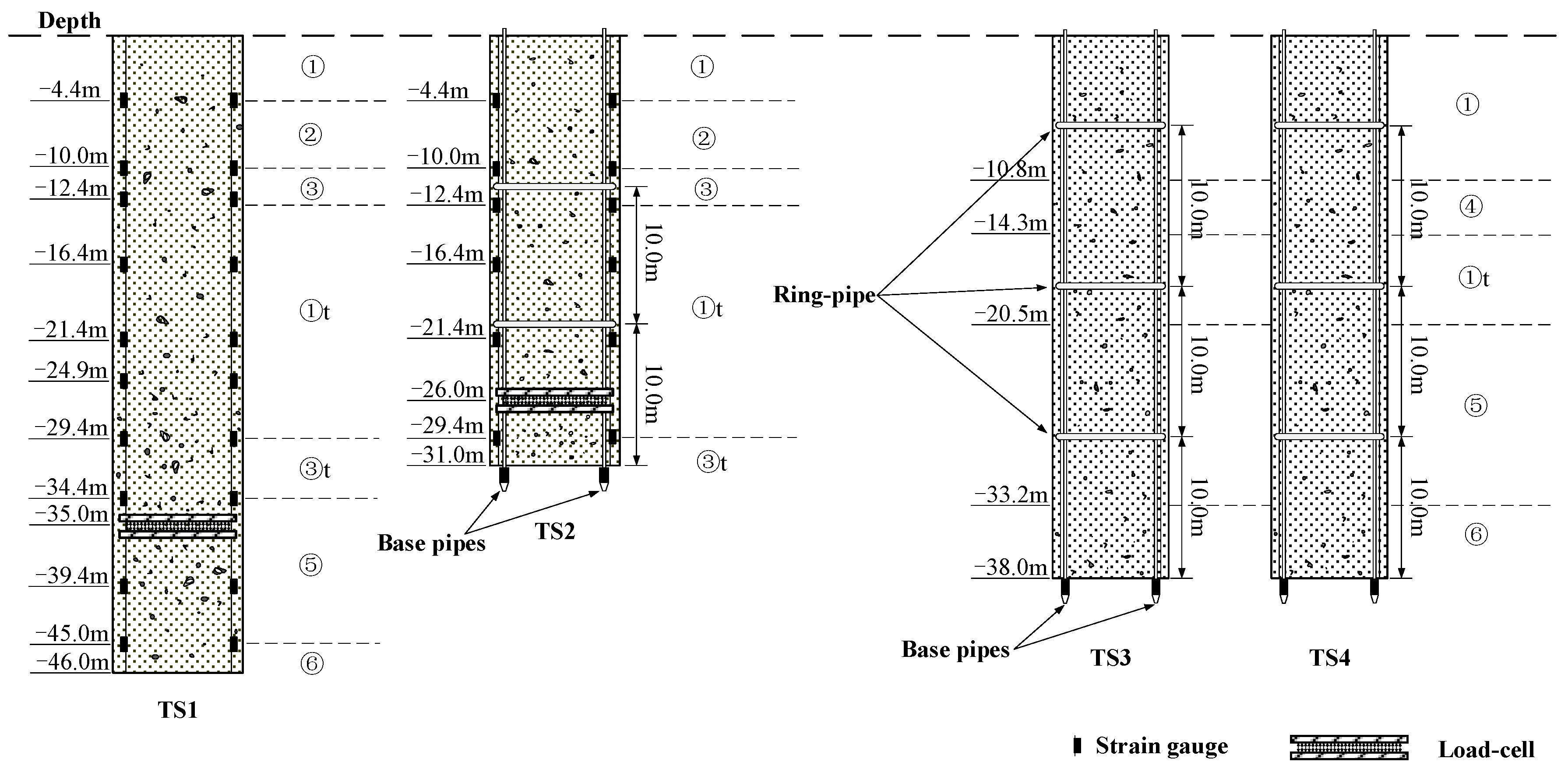
2. Site Description and Test Shafts Details
3. Grouting and Loading Test
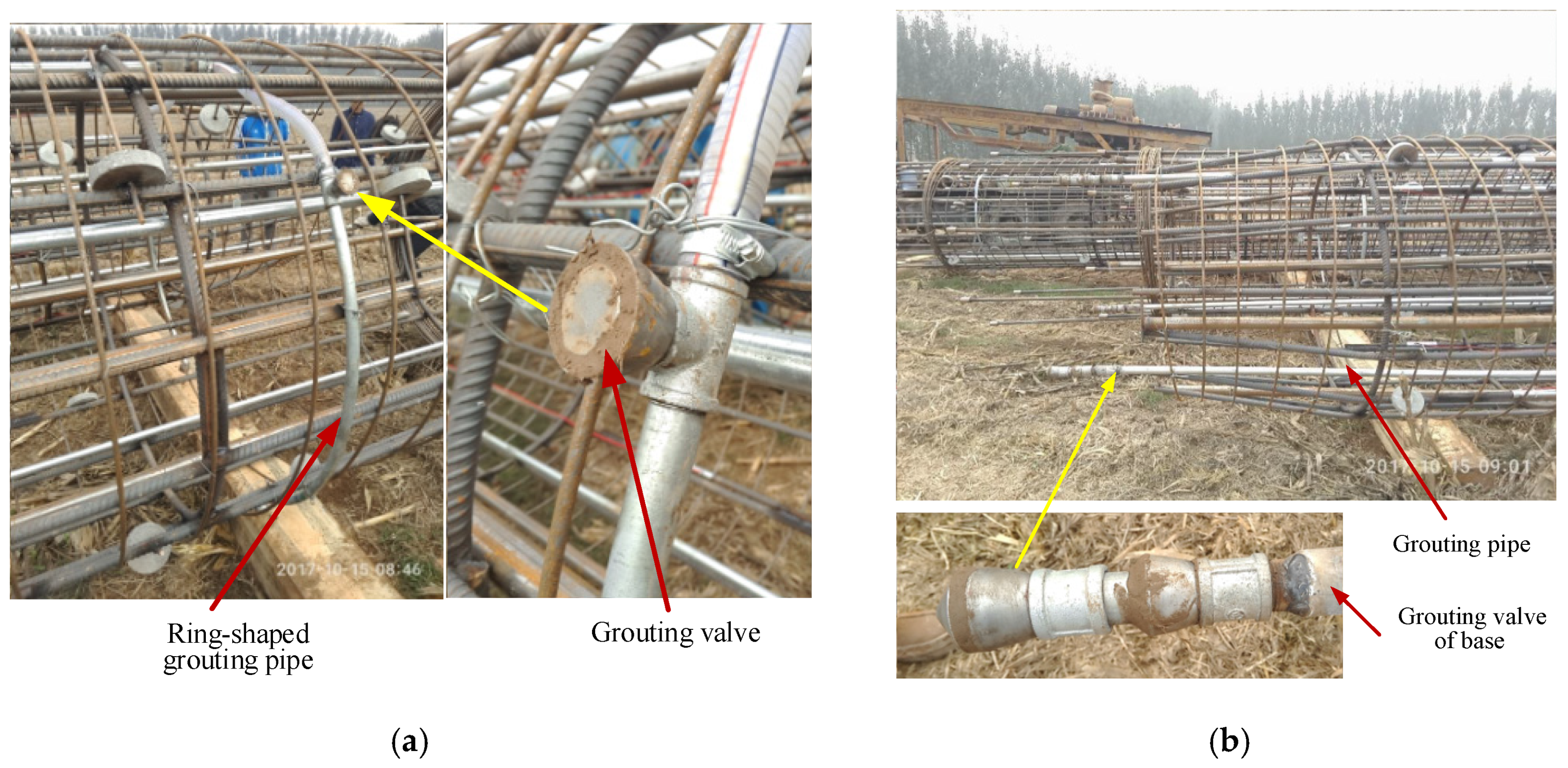
3.1. Post-Grouting Operation
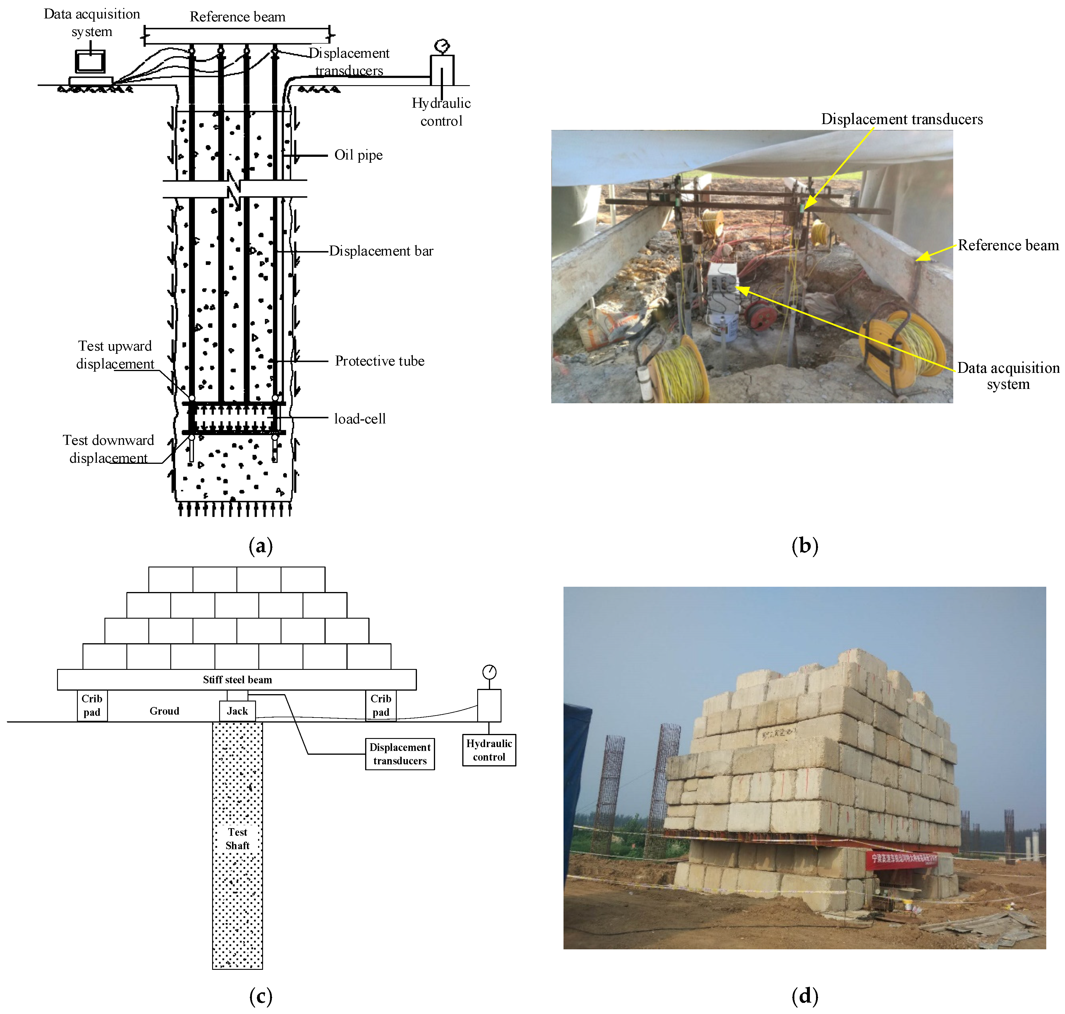
3.2. Test Methods
3.3. Test Procedures
4. Prediction of SPT Blow Counts
4.1. Prediction Model
4.2. Prediction and Analysis of SPT Blow Counts
5. Results and Discussion
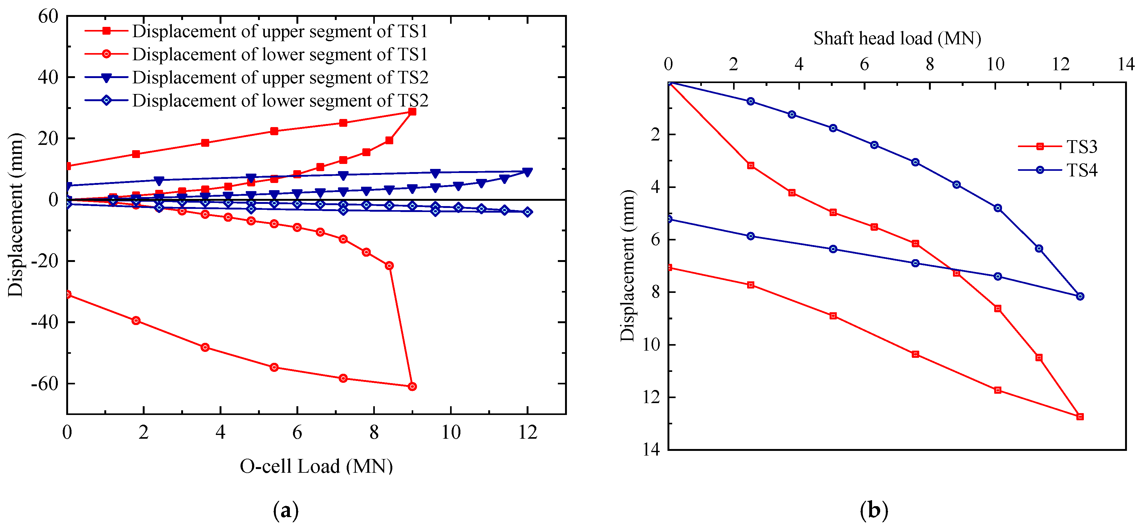
5.1. Load-Displacement Responses
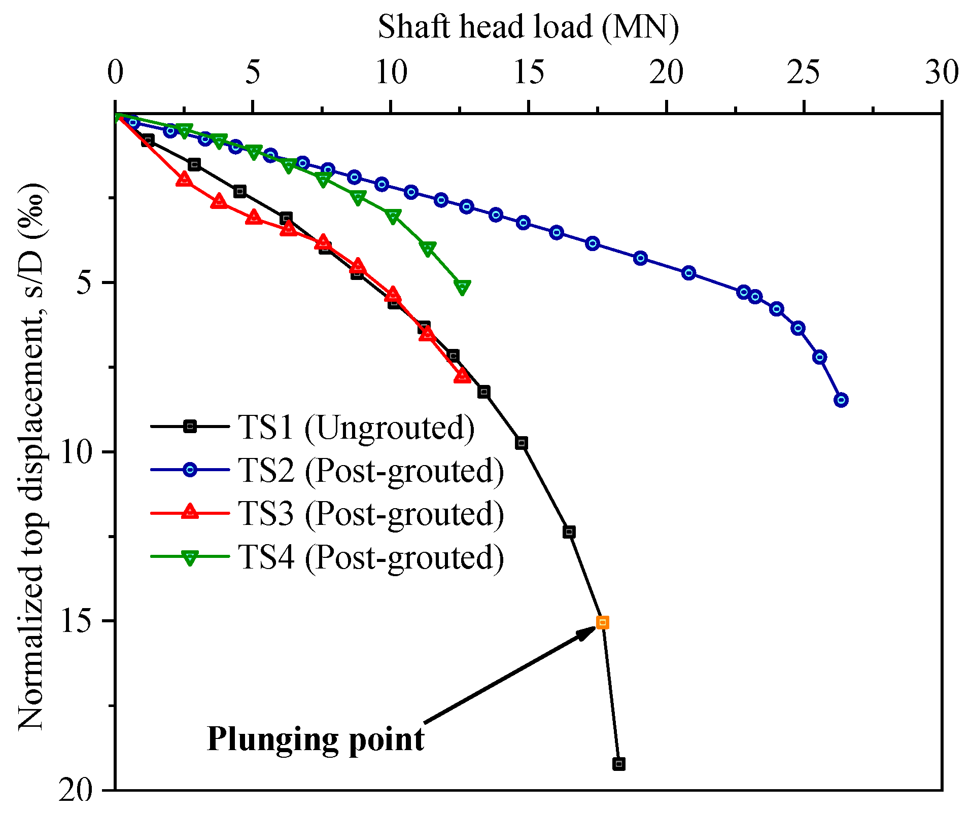
5.2. Responses of Shaft Top Load Versus Normalized Displacement
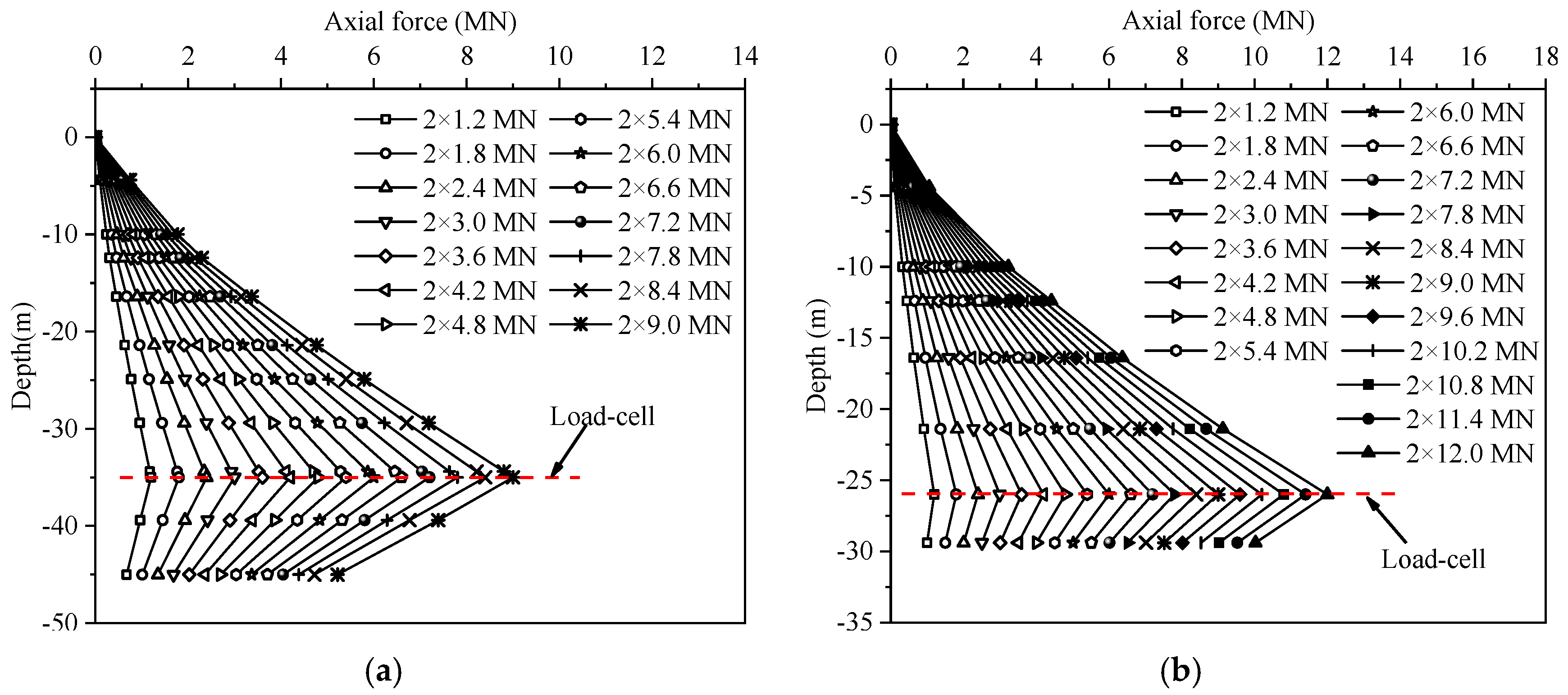
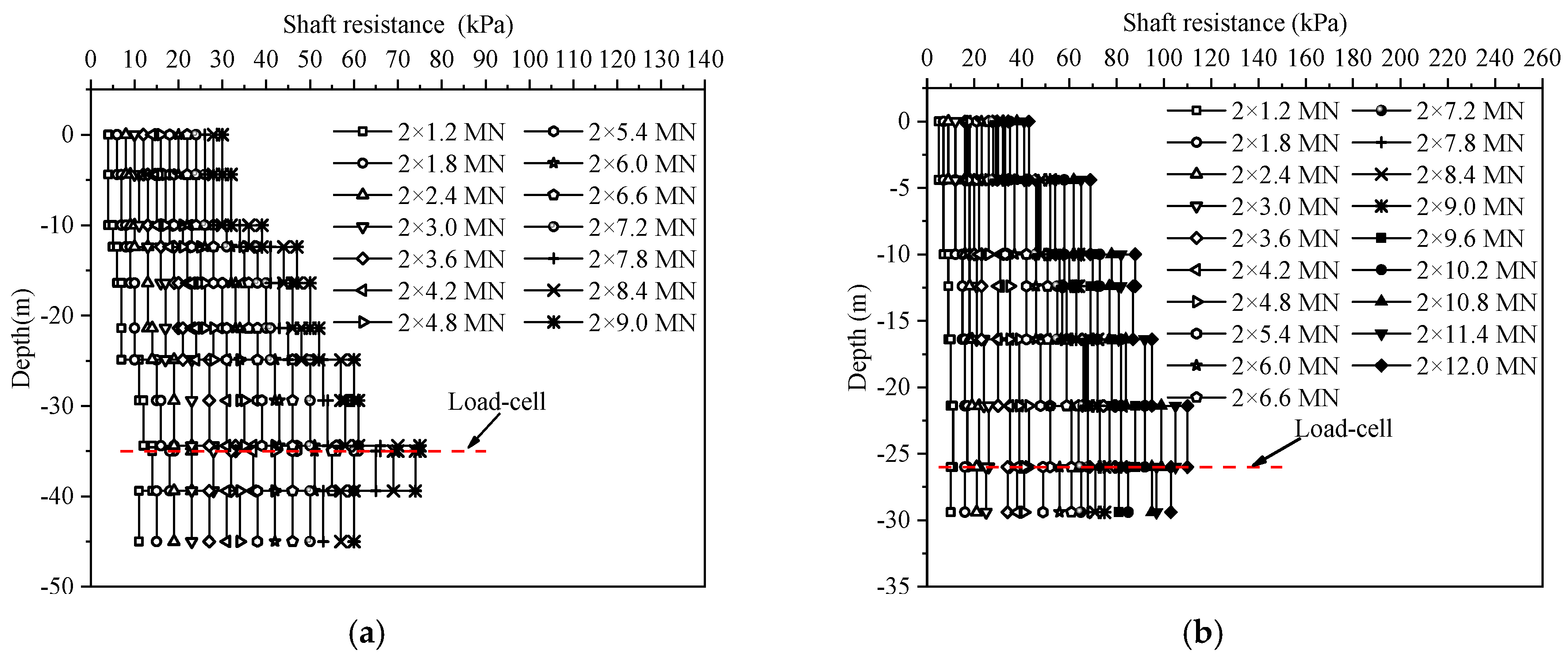
5.3. Distribution of Axial Force on Test Shafts
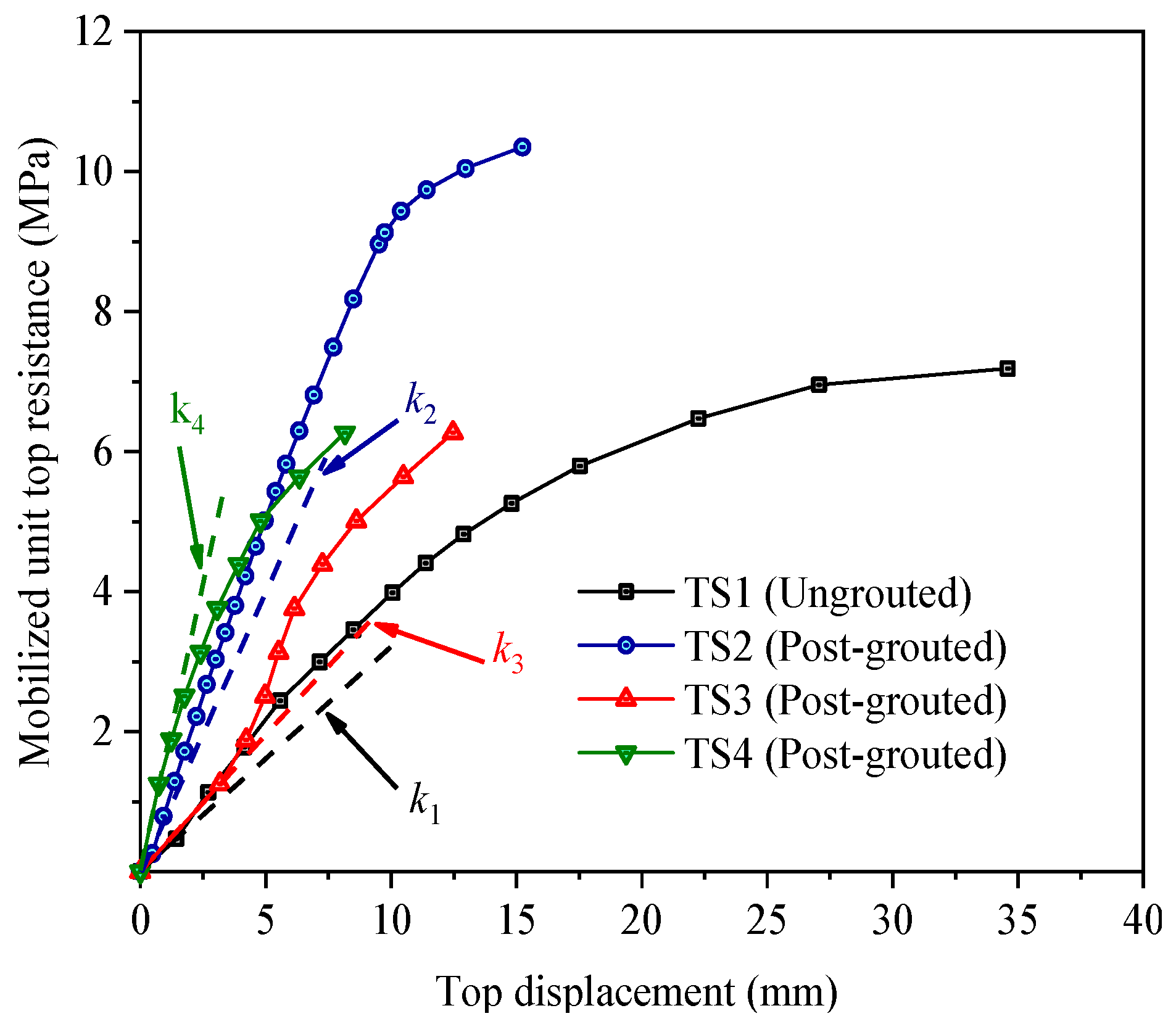
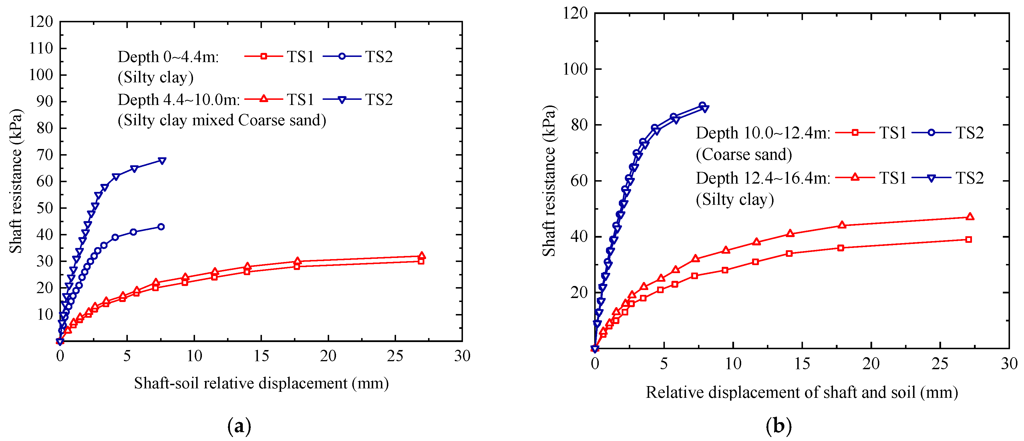
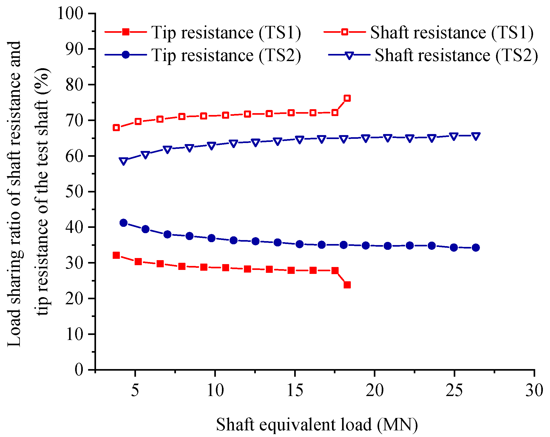
5.4. Mobilized Shaft Resistance
5.5. Mobilized Tip Resistance
6. Conclusions
- Post-grouting drilled shaft has great advantages in terms of economy and safety. The bearing characteristics of the shaft can be effectively enhanced by using the combined tip and side post grouting technique. The load was determined to be 10.08 MN, the corresponding normalized displacements of control shaft (TS1) and grouted shaft (TS2, TS3 and TS4) were 5.56‰ D, 2.18‰ D, 5.39‰ D and 3.00‰ D, respectively.
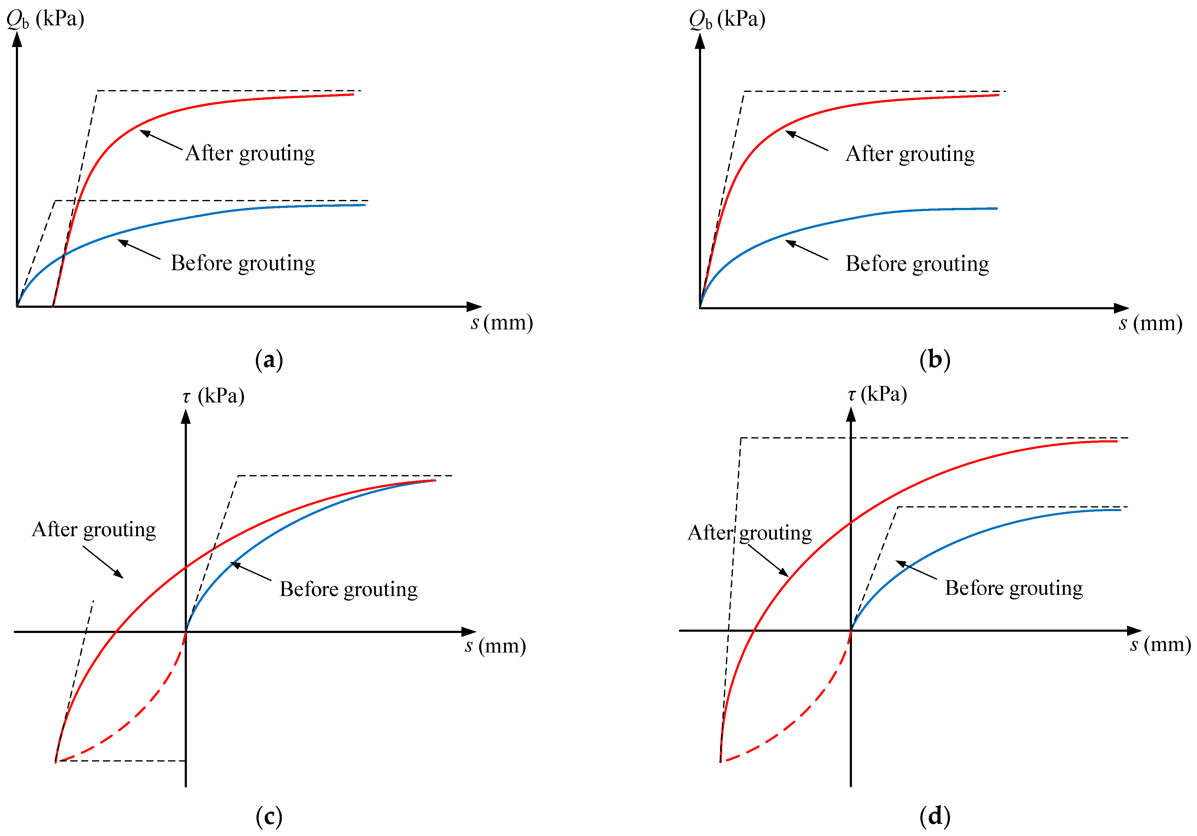
- The index of shaft tip grouting has a significant influence on the performance of the test shaft. Pre-mobilization that tends to stiffen the response of post grouted drilled shaft but not increase the ultimate tip resistance, whereas ground improvement at the shaft tip and enlargement of the shaft tip would increase the ultimate tip resistance.
- The SPT blow counts of soil increased after grouting, and it is nonlinear with the increase of soil strength parameters. The SPT blow counts of cohesive soil increased by about 12.5~160%, and the SPT blow counts of cohesionless soil increased by about 69.2~200%.
- The pressurized cement grout can improve the physical and mechanical properties of the soil layers surround the shaft and the shaft–soil interface, and the enhancement effect is more significant for cohesionless soil.
- Tip resistance of shaft can be mobilized more rapidly and fully after grouting, and the side and tip resistance are mobilized in a more synchronized and coordinated manner due to the pre-mobilization of the grouted cement.
- Although the designed tip grouting quantity of test shaft TS3 was not reached, the bearing capacity required for the design load of shaft TS3 was fully met.
Author Contributions
Funding
Institutional Review Board Statement
Informed Consent Statement
Data Availability Statement
Acknowledgments
Conflicts of Interest
References
- Bruce, D.A. Enhancing the performance of large diameter piles by grouting. Ground Eng. 1986, 19, 9–15. [Google Scholar]
- Majano, R.E.; O’Neill, M.W.; Hassan, K.M. Perimeter load transfer in model drilled shafts formed under slurry. J. Geotech. Eng. 1994, 120, 2136–2154. [Google Scholar] [CrossRef]
- Sliwinski, Z.J.; Fleming, W.G.K. The integrity and performance of bored piles. In Piling and Ground Treatment; Thomas Telford Publishing: London, UK, 1984; pp. 211–223. [Google Scholar]
- Stocker, M.F. Influence of post-grouting on the load-bearing capacity of bored piles. In Proceedings of the 8th European Conference on Soil Mechanics and Foundation Engineering, Helsinki, Finland, 23–26 May 1983; pp. 167–170. [Google Scholar]
- Zhang, Z.M.; Yu, J.; Zhang, G.X.; Zhou, X.M. Test study on the characteristics of mudcakes and in situ soils around bored piles. Can. Geotech. J. 2009, 46, 241–255. [Google Scholar] [CrossRef]
- Wan, Z.H.; Dai, G.L.; Gong, W.M. Field study on post-grouting effects of cast-in-place bored piles in extra-thick fine sand layers. Acta Geotech. 2019, 14, 1357–1377. [Google Scholar] [CrossRef]
- Zhang, Z.T.; Gong, W.M.; Dai, G.L.; Xu, J. Enhancement of load bearing of post-grouted drilled shafts based on in situ tests. Arab. J. Geosci. 2021, 14, 1–13. [Google Scholar] [CrossRef]
- El-Kelesh, A.M.; Matsui, T.; Tokida, K. Field investigation into effectiveness of compaction grouting. J. Geotech. Geoenviron. Eng. 2012, 138, 451–460. [Google Scholar] [CrossRef] [Green Version]
- Wan, Z.H.; Dai, G.L.; Gong, W.M. Field and theoretical analysis of response of axially loaded grouted drilled shafts in extra-thick fine sand. Can. Geotech. J. 2020, 57, 391–407. [Google Scholar] [CrossRef]
- Fiscina, L.F.G.; Barbosa, Y.; Albuquerque, P.J.R.D.; Carvalho, D.D. Field study on axial behavior of instrumented post-grouted steel pipe micropiles in tropical lateritic soil. Innov. Infrastruct. Solut. 2021, 6, 1–17. [Google Scholar] [CrossRef]
- Sinnreich, J.; Simpson, R.C. Case histories of full-scale comparative load testing of base grouted and Ungrouted test shaft pairs. In Proceedings of the IFCEE 2015, San Antonio, TX, USA, 17–21 March 2015; pp. 486–499. [Google Scholar]
- Frizzi, R.P.; Meyer, M.E.; Zhou, L.J. Full Scale Field Performance of Drilled Shafts Constructed Utilizing Bentonite and Polymer Slurries. In GeoSupport 2004: Drilled Shafts, Micropiling, Deep Mixing, Remedial Methods, and Specialty Foundation Systems; Geotechnical Special Publication: Orlando, FL, USA, 2004; pp. 573–586. [Google Scholar]
- Ruiz, M.E.; Pando, M.A. Load transfer mechanisms of tip post-grouted drilled shafts in sand. In Proceedings of the International Foundation Congress and Equipment Expo 2009, Orlando, FL, USA, 15–19 March 2009; pp. 23–30. [Google Scholar]
- Thiyyakkandi, S.; McVay, M.; Bloomquist, D.; Lai, P. Measured and predicted response of a new jetted and grouted precast pile with membranes in cohesionless soils. J. Geotech. Geoenviron. Eng. 2013, 139, 1334–1345. [Google Scholar] [CrossRef]
- Dai, G.L.; Gong, W.M.; Xue, G.Y.; Tong, X.D. Effect examination for a base post-grouted overlength drilling pile. Rock Soil Mech. 2006, 27, 849–852. [Google Scholar]
- Day, T.J.; Boeckmann, A.Z.; Loehr, J.E. Separating contributions from pre-mobilization and ground improvement for post-grouted drilled shafts. In Proceedings of the IFCEE 2015, San Antonio, TX, USA, 17–21 March 2015; pp. 951–960. [Google Scholar]
- Wen, L.; Kong, G.Q.; Li, Q.S.; Zhang, Z.D. Field Tests on Axial Behavior of Grouted Steel Pipe Micropiles in Marine Soft Clay. Int. J. Geomech. 2020, 20, 06020006. [Google Scholar] [CrossRef]
- Mullins, G.; Winters, D.; Dapp, S. Predicting end bearing capacity of post-grouted drilled shaft in cohesionless soils. J. Geotech. Geoenviron. Eng. 2006, 132, 478–487. [Google Scholar] [CrossRef] [Green Version]
- Thompson, P.A. Base and shaft grouted piles. Proc. Inst. Civ. Eng. Geotech. Eng. 1996, 119, 186–192. [Google Scholar] [CrossRef]
- Duan, X.S.; Kulhawy, F.H. Tip Post-Grouting of Slurry-Drilled Shafts in Soil: Chinese Experiences; Contemporary Topics in Deep Foundations: Orlando, FL, USA, 2009; pp. 47–54. [Google Scholar]
- Fang, K.; Zhang, Z.M.; Zhang, Q.Q.; Liu, X.W. Prestressing effect evaluation for a grouted shaft: A case study. Proc. Inst. Civ. Eng.-Geotech. Eng. 2014, 167, 253–261. [Google Scholar] [CrossRef]
- Tan, Y.; Lu, Y.; Peng, F.; Liao, S.M. Post-Grouting of long bored piles in clay. In Proceedings of the Grouting 2017, Honolulu, HI, USA, 9–12 July 2017; pp. 338–347. [Google Scholar]
- Fernandez, A.L.; Pando, M.A.; King, P.G. Load test program to validate model for post grouted drilled shafts. In Proceedings of the Geo-Denver 2007, Denver, CO, USA, 18–21 February 2007; pp. 1–11. [Google Scholar]
- Ministry of Water Resources of the People’s Republic of China. GB/T 50123-1999 Standard for Soil Test Method; China Planning Press: Beijing, China, 1999. (In Chinese)
- The Traffic Professional Standards Compilation Group of People’s Republic of China. JT/T 738-2009 Static Loading Test of Foundation Pile-Self-Balanced Method; China Communications Press: Beijing, China, 2009. (In Chinese)
- People’s Republic of China Industry Standards Writing Group. JGJ 106-2014 Technical Specifications for Building Pile Testing; China Building Industry Press: Beijing, China, 2014. (In Chinese)
- Meyerhof, G.G. Bearing capacity and settlement of pile foundations. J. Geotech. Eng. Div. 1976, 102, 197–228. [Google Scholar] [CrossRef]
- Zhang, X.M.; Wang, J.H.; Li, S.B.; Du, Q. New method for estimation of ultimate bearing capacity of friction pile. Chin. J. Rock Mech. Eng. 2004, 23, 2305–2311. [Google Scholar]
- Liu, J.L. Estimation of ultimate bearing capacity of pile with SPT blow count. Geotech. Eng. Tech. 2002, 2, 88–91. [Google Scholar]
- Wan, Z.H.; Dai, G.L.; Gong, W.M. Full-scale load testing of two large-diameter drilled shafts in coral-reef limestone formations. Bull. Eng. Geol. Environ. 2018, 77, 1127–1143. [Google Scholar] [CrossRef]


| Layer | Stratum Description | Thickness of Each Soil Layer/m | ω (%) | γ (kN/m3) | c (kPa) | φ (°) | |||
|---|---|---|---|---|---|---|---|---|---|
| TS1 | TS2 | TS3 | TS4 | ||||||
| ① | Silty clay | 4.4 | 4.4 | 10.8 | 10.8 | 25.7 | 19.0 | 41.1 | 11.7 |
| ② | Silty clay mixed Coarse sand | 5.6 | 5.6 | 24.5 | 19.4 | 31.7 | 25.3 | ||
| ③ | Coarse sand | 2.4 | 2.4 | 30 | 18.4 | 18.5 | 6.1 | ||
| ④ | Fine sand | 3.5 | 3.5 | 26.3 | 19.1 | 21.3 | 9.4 | ||
| ①t | Silty clay | 17.0 | 17.0 | 6.2 | 6.2 | 25.7 | 19.2 | 11.7 | 4.9 |
| ③t | Coarse sand | 5.0 | 1.6 | 26.2 | 18.4 | 3.7 | 18.9 | ||
| ⑤ | Silty clay | 10.6 | 12.7 | 12.7 | 23.7 | 19.2 | 44.3 | 15.8 | |
| ⑥ | Coarse sand | 1.0 | 4.8 | 4.8 | 22.0 | 18.5 | 4.3 | 25.9 | |
| Shaft No. | Diameter (m) | Length (m) | Concrete Grade | O-Cell above Shaft Tip (m) |
|---|---|---|---|---|
| TS1 | 1.8 | 46 | C30 | 11 |
| TS2 | 1.8 | 31 | C30 | 5 |
| TS3 | 1.6 | 38 | C30 | - |
| TS4 | 1.6 | 38 | C30 | - |
| Shaft No. | Design Quantity (kg) | Actual Quantity (kg) | Number of Grouting Pipes | Grouting Pressure (MPa) | |
|---|---|---|---|---|---|
| Straight Pipes, Side Pipes | C1, C2, C3 | D1, D2, D3, D4 | |||
| TS2 | 7380 | 8400 | 3, 2 | 1.711, 0.461, _ | 2.2–2.5 |
| TS3 | 10,300 | 8375 | 4, 3 | 1.689, 1.212, 0.521 | 2.0–2.8 |
| TS4 | 10,300 | 10,460 | 4, 3 | 1.727, 1.182, 0.642 | 2.2–3.4 |
| Shaft No. | Limit Load (MN) | Loading Increments | Load Per Level (kN) | Initial Load (kN) |
|---|---|---|---|---|
| TS1 | 2 × 9.0 | 14 | 2 × 600 | 2 × 1200 |
| TS2 | 2 × 12.0 | 19 | 2 × 600 | 2 × 1200 |
| TS3 | 12.6 | 9 | 1260 | 2520 |
| TS4 | 12.6 | 9 | 1260 | 2520 |
| Shaft No. | Quu (kN) | Qlu (kN) | Length of Upper Shaft Segment (m) | W (kN) | γc | Pu (kN) |
|---|---|---|---|---|---|---|
| TS1 | 9000 | 8400 | 35 | 1291 | 0.78 | 18,283 |
| TS2 | 12,000 | 12,000 | 26 | 959 | 0.77 | 26,339 |
| Layer | α | ξ | μ |
|---|---|---|---|
| ① | 100.0010 | 37.0370 | 0.1207 |
| ② | 100.0105 | 136.8877 | 0.2782 |
| ③ | 100.0104 | 36.0832 | 0.0479 |
| ④ | 100.0168 | 62.8278 | 0.1138 |
| ①t | 99.9910 | 94.5084 | 0.2309 |
| ③t | 99.9956 | 51.0261 | 0.1501 |
| ⑤ | 100.0011 | 40.7986 | 0.1842 |
| ⑥ | 99.9931 | 58.2229 | 0.2329 |
| Layer | Before Grouting | After Grouting | Improvement of SPT Blow Counts (%) | ||
|---|---|---|---|---|---|
| the Ultimate Side Resistance (kPa) | Tested SPT Blow Count | the Ultimate Side Resistance (kPa) | Predicted SPT Blow Counts | ||
| ① | 35 | 8 | 37 | 9 | 12.5 |
| ② | 40 | 14 | 55 | 31 | 121.4 |
| ③ | 45 | 13 | 76 | 22 | 69.2 |
| ④ | 35 | 14 | |||
| ①t | 50 | 22 | 75 | 39 | 77.3 |
| ③t | 60 | 19 | 90 | 45 | 136.8 |
| ⑤ | 60 | 15 | 98 | 39 | 160.0 |
| ⑥ | 65 | 20 | 100 | 60 | 200.0 |
| Shaft No. | Maximum Load (MN) | Maximum Displacement (mm) | Maximum Rebound (mm) | Rebound Rate (%) | ||||
|---|---|---|---|---|---|---|---|---|
| Upward | Downward | Upward | Downward | Upward | Downward | Upward | Downward | |
| TS1 | 9.0 | 9.0 | 28.73 | 60.97 | 17.76 | 30.03 | 61.82 | 49.25 |
| TS2 | 12.0 | 12.0 | 9.27 | 4.01 | 4.61 | 1.44 | 50.27 | 64.09 |
| TS3 | 12.6 | 12.74 | 5.68 | 44.58 | ||||
| TS4 | 12.6 | 8.16 | 2.94 | 36.03 | ||||
Publisher’s Note: MDPI stays neutral with regard to jurisdictional claims in published maps and institutional affiliations. |
© 2021 by the authors. Licensee MDPI, Basel, Switzerland. This article is an open access article distributed under the terms and conditions of the Creative Commons Attribution (CC BY) license (https://creativecommons.org/licenses/by/4.0/).
Share and Cite
Zhang, Z.; Gong, W.; Dai, G.; Cao, X.; Zhu, Y.; Huang, H. Field Tests on Bearing Characteristics of Large-Diameter Combined Tip-and-Side Post Grouted Drilled Shafts. Appl. Sci. 2021, 11, 11883. https://doi.org/10.3390/app112411883
Zhang Z, Gong W, Dai G, Cao X, Zhu Y, Huang H. Field Tests on Bearing Characteristics of Large-Diameter Combined Tip-and-Side Post Grouted Drilled Shafts. Applied Sciences. 2021; 11(24):11883. https://doi.org/10.3390/app112411883
Chicago/Turabian StyleZhang, Zhitong, Weiming Gong, Guoliang Dai, Xiaolin Cao, Yu Zhu, and Hao Huang. 2021. "Field Tests on Bearing Characteristics of Large-Diameter Combined Tip-and-Side Post Grouted Drilled Shafts" Applied Sciences 11, no. 24: 11883. https://doi.org/10.3390/app112411883
APA StyleZhang, Z., Gong, W., Dai, G., Cao, X., Zhu, Y., & Huang, H. (2021). Field Tests on Bearing Characteristics of Large-Diameter Combined Tip-and-Side Post Grouted Drilled Shafts. Applied Sciences, 11(24), 11883. https://doi.org/10.3390/app112411883