Article

Implementation of a Floating Head Pressure Condensation Control to Reduce Electrical Energy Consumption in an Industrial Refrigeration System

by
Fábio Luiz da Costa Carrir
1,2,
Cesare Biserni
3,*,
Danilo Barreto Aguiar
4,
Elizaldo Domingues dos Santos
1,4 and
Ivoni Carlos Acunha Júnior
1,2
1
Graduate Program of Computational Modeling, Federal University of Rio Grande—FURG, Italia Avenue, km 8, Rio Grande 96201-900, Brazil
2
Refrigeration Department, Federal Education Science and Technology Institute of Rio Grande do Sul-IFRS, Alfredo Huch Engineer St., 475, Rio Grande 96201-900, Brazil
3
Department of Industrial Engineering, Alma Mater Studiorum, University of Bologna, Viale Risorgimento 2, 40136 Bologna, Italy
4
School of Engineering, Federal University of Rio Grande—FURG, Italia Avenue, km 8, Rio Grande 96201-900, Brazil
*
Author to whom correspondence should be addressed.
Appl. Sci. 2021, 11(24), 11923; https://doi.org/10.3390/app112411923
Submission received: 8 October 2021 / Revised: 11 December 2021 / Accepted: 13 December 2021 / Published: 15 December 2021
(This article belongs to the Section Applied Thermal Engineering)

Abstract

:

Featured Application

Featured Application: The present work shows the importance of controlling pressure condensation to reduce the consumption of electric energy in refrigeration system. The developed system of control was validated by means of application in a laboratory scale evaporative condenser. The results showed that the system also efficiently reduces electric consumption in an industrial refrigeration system.

Abstract

The growing global demand for energy and the costly taxes on electric energy demonstrate the importance of seeking new techniques to improve energy efficiency in industrial facilities. Refrigeration units demand a large amount of electricity due to the high power needs of the components of the system. One strategy to reduce the electric energy consumption in these facilities is pressure condensation control. The objective here was to develop a logical control model where the physical quantities in the thermodynamic process can be monitored and used to determine the optimum point of the condensation pressure and the mass flow rate of the air in the evaporative condenser. The algorithm developed was validated through experiments and was posteriorly implemented in an ammonia industrial system of refrigeration over a period of sixteen months (480 days). The results showed that the operation of the evaporative condenser with a controlled air mass flow rate by logical modeling achieved a reduction of 7.5% in the consumption of electric energy, leading to a significant reduction in the operational cost of the refrigeration plant.

1. Introduction

The population growth and economic development of countries has resulted in increasing demands for electricity over the years. Moreover, the costs of energy can be very high, which can be justified by several reasons, including difficulties that arise during the electricity generation process [1].
The food industry is the sector with the highest consumption of electric energy in the world, representing approximately 42% of the total demand [1]. In this industry, there are large food processing companies that require industrial refrigeration systems. One important aspect is that these refrigeration systems demand a large amount of electricity due to the high thermal loads, long periods of operation, and high power demands from the equipment, which also leads to high consumption of electricity for driving the devices.
An efficient way to reduce electric energy consumption in a refrigeration system is to modify the operation condensation pressure (OCP). Another important alternative is the use of mathematical and computational modeling to simulate various conditions. In this context, the use of the grey-box model has led to several important results using data acquired from the refrigeration system during its operation [2,3]. The correct sizing of the condenser and the control of the fans have significant effects on the total electricity demand of the refrigeration system [4]. One strategy that can be used is a floating head pressure condensation control (FHPCC). For instance, Lu et al. [5] achieved an increase in COP in a recirculating system of ammonia when associating the FHPCC technique with compressors of variable speed. In addition, in some situations, the refrigeration system operates partially loaded during the year. Chang and Yu [6] performed a study to identify the energy consumption savings in an air-cooled reciprocating multiple-chiller plant under conventional pressure control and a new condensation-temperature control. There was a substantial efficiency drop during partial loaded operation due to the pressure control compared with the control of the condensation temperature, with potential energy savings of 18.2% and 29% for the annual cooling energy consumption.
The pressure condensation control can be performed by means of changes in the rotation velocity of the fans of the electric motors of the evaporative condenser. Thus, the modulation allows for modification of the heat transfer rate and, therefore, directly impacts the condensation pressure of the refrigeration system. In the study of Yu and Chang [7], it was found that the use of condenser fans with FHPCC applied in chillers, which work with screw compressors, allowed for the operation of the refrigeration system at a higher efficiency than the system without any control. The use of different strategies to control the drive of compressors and fans in refrigeration systems was shown to be an important strategy to reduce electric energy consumption in comparison with the traditional drive system of this equipment. This behavior has previously been demonstrated in the literature [8,9,10,11,12].
An efficient way to save electricity is the use of a variable speed drive (VSD) to control the rotation of electric motors. According to the behavior of the blowers, the power consumed by the electric motor of the fan varies as the cube of its speed [13]. There is a significant global reduction in energy consumption in HVAC (heating, ventilation, and air conditioning) systems when VSDs are employed in motors in comparison with equipment that operates at constant rotation [14,15]. Al-bassam and Alasseri [16] demonstrated a decrease of 5.8% in the combined power in a chiller and cooling tower when installing VSD in the fans of the heat exchanger in comparison with a system with dual velocity. Afterward, Yu et al. [17] analyzed the significant economic benefits of four different strategies of operation using VSD in the fans of an air condenser in one chiller, and the annual electricity consumption dropped by 5.91% in VSD mode.
As mentioned above, various studies on refrigeration and energy efficiency have been presented in experimental and numerical frameworks using theoretical data at the laboratory scale. However, it is not common to find experiments where ammonia is the working refrigerant fluid and the study is conducted in an actual industrial environment, as performed here. For each environmental condition and thermal load that a unit is subjected to, there is a condensation temperature that results in the lowest global electric energy consumption. Thus, the logical model developed here can be an important tool for minimizing energy waste in the industrial refrigeration realm. In this sense, this research has as an objective the development of logical control modeling, in which the present physical quantities in the thermodynamic process can be analyzed and used to implement actions to modulate the rotation of evaporative condenser fans. Consequently, the mass flow rate of the air in the evaporative condenser is controlled to modify the condensation pressure to remain within magnitudes that result in less electricity demand.

2. Methodology

In this section, information about the experimental bench used to configure the logical control model, the configuration of the refrigeration unit monitored over sixteen months, and an explanation of the working principle of the developed logical control model are presented.

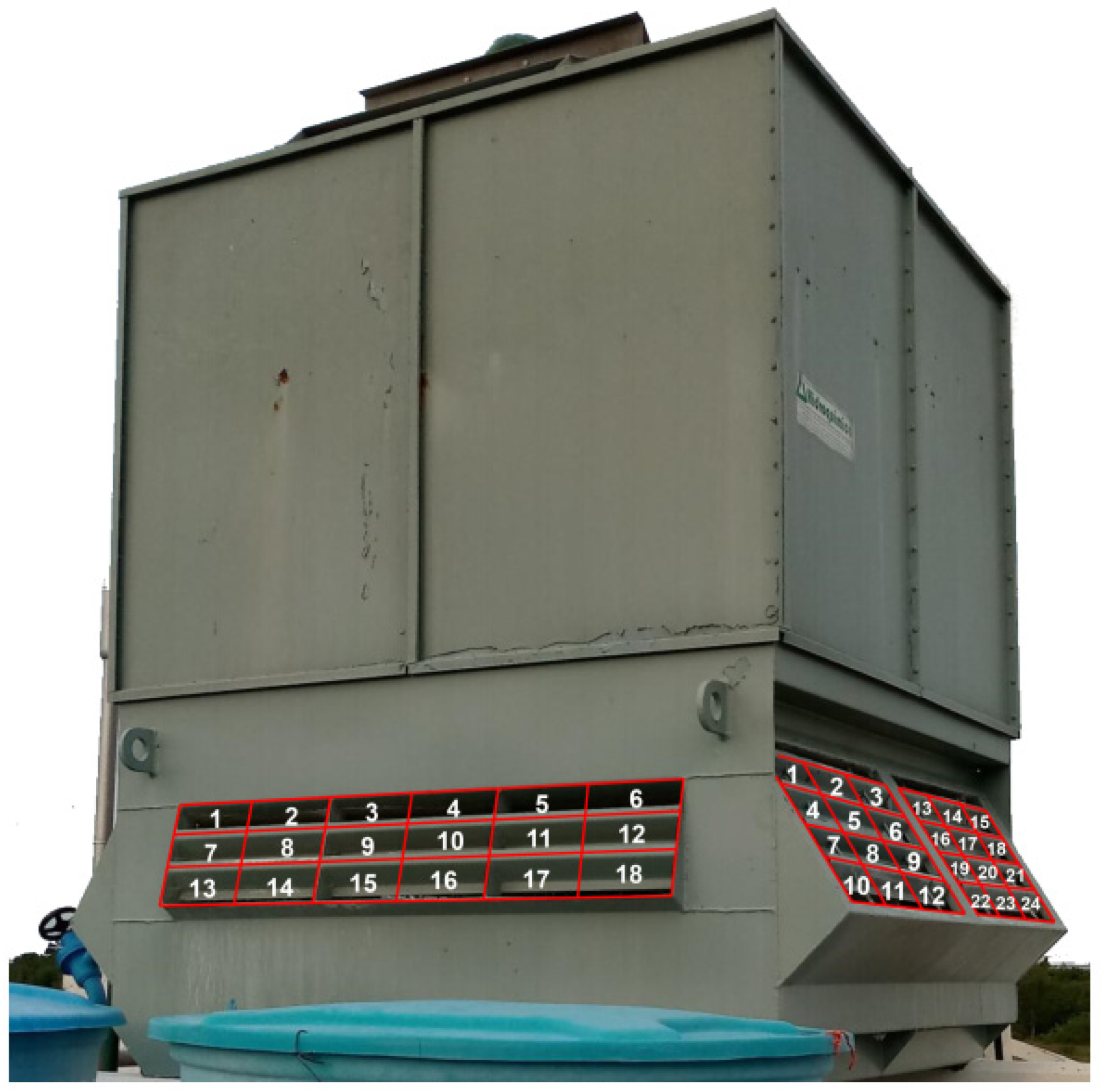
2.1. Experimental Bench

The logical model developed was tested in an experimental bench before being deployed in an ammonia refrigeration system. The main purpose was to identify patterns of variations of condensation head pressure and its relationship with other variables, allowing for the modulation of the mass flow rate of air in the evaporative condenser (EC).
The experimental bench consisted of a refrigeration system of vapor compression that uses R-22 as a refrigerant working fluid operating in the laboratory. R-22 was choose as the refrigerant fluid due to its lower toxicity in comparison to R-717, together with its low corrosion potential to the evaporative condenser tubes, which are made of copper.
A schematic configuration of that bench is shown in Figure 1. It consisted of a unit of an air conditioner with a capacity of 2.2 kW. The unit was composed of a hermetic alternative compressor model, with demanded power of 0.186 kW, a capillary tube, one evaporator with forced ventilation, an evaporative condenser on a reduced scale of one-fourth in comparison with a commercially produced model [18], one VFD model CFW10 easydrive, and one programmable logic controller (PLC) where logical control modeling was implemented. It is worth mentioning that this was previously used in the study of Acunha and Schneider [18].
The measurement data of some variables of the refrigeration system were directly connected with the PLC, which provides the read and storage of the quantities in a database created for this purpose. These data were collected continuously with a defined time interval between readings. The measurement points and the respective information collected are shown in Figure 1. Point 1 represents the location where the condensation pressure (P in bar) and R-22 temperature (T in °C) measurements are made at the inlet of EC, while Point 2 depicts the pressure (P in bar) measurement of R-22 leaving the EC. Points 3 and 4 represent R-22 at the inlet and outlet airflow rates of the EC, respectively, where the velocity (V in m/s), dry bulb temperature (TDB in °C), and relative humidity (UR in %) measurements are realized. At Point 5, the volumetric flow rate (Q in m3/s) of the water is measured, while at Point 6, the sump temperature (T in °C) is acquired. Temperature measurements of the water and R-22 were performed by PT-100 sensors with an uncertainty of ±0.1 °C. The dry bulb temperature (TDB) and wet bulb temperature (TWB) of the airflow rate at the inlet and outlet EC were measured by an HT-270 thermohygrometer with an uncertainty of ±0.8 °C for temperature and 4.0% of the measured value for relative humidity. The air velocity was measured by an anemometer with an uncertainty of ±0.1 m/s. The uncertainty of the R-22 pressure measurements was 0.067 bar. Concerning the energy consumption, one analyzer of energy with an uncertainty of ±1.0% of the measured value was considered. The same measurement equipment used to collect information in the experimental bench of R-22 refrigeration system were employed for measurements of the ammonia industrial refrigeration unit. In this study, we did not analyze the relation between the inlet temperature of the air in the EC and the performance of the refrigeration unit.
Initially, experiments were performed by changing the mass flow rates of the air through the EC and systematically varying the frequency driver of the fan with 5 Hz steps in the range of 10 Hz ≤ f ≤ 50 Hz. When the frequency changed for a new value, this magnitude was kept constant until the refrigeration system reached a stable condition; in such way the measurements were calculated with a higher accuracy. It is worth mentioning that only the frequency was kept constant during this time interval, with the remaining variables free to vary. The same measurement procedure was used for the study in the field of the industrial refrigeration unit. The sole difference was the range of frequency where the EC fans operated.
Thus, for each sample, the measured variables were saved, and the results served as the basis to identify patterns involved in the condensation pressure. This variation allowed for identification of the operational criterion that made the system operate with the lowest possible electricity consumption. It is worth mentioning that the investigation of the parameters related to the bench, such as the thermal load and evaporation temperature was not performed. The objective of the bench operation was just to demonstrate that the operation of the fans’ motor of the EC under varied frequencies could result in a minimal consumption of the refrigeration system (set of fans and compressor).
After identifying the existing relationships between the involved quantities of the refrigeration system, the logical control modeling developed automatically made operational decisions. Logical modeling was implemented in a PLC, and after tests alternating the manual and automatic operation modes, similar trends of the results were observed with both operation modes.
It is worth mentioning that the laboratory scale R22 system was studied to perform a sort of validation of the methodology used in the present work, as well as to verify whether the variation of pressure condensation over the system performance was similar to previous findings in the literature.

2.2. Industrial Refrigeration System

The logical model developed was employed in an industrial food freezing system after the tests with the experimental bench and studied for a period of 16 months (480 days). The EC used locally had a heat transfer rate rejection capacity of qrej = 349 kW. The EC had two fan motor drives with an electric motor with a power of Pmotor = 3 kW and had the following nominal conditions of the project: wet bulb temperature equal to TBU = 24 °C and condensation temperature of TC = 35 °C. The refrigeration system had two compressors (C1 and C2) with capacities of 60.35 kW and 80.76 kW, operating at −35/+35 °C. Both compressors had oil separators. In the present investigation, only C1 was working during the measurements realized. All the evaporators were overfeed with pumps directly linked to a liquid separator that drove the refrigerant fluid in the heat exchangers. Moreover, the evaporators were finned and forced convection hot gas flow was used for defrost.
For the measurements of inlet air velocity, the four sides of the EC were divided so that the two largest sides had 24 measurement points, while the other two smaller sides were divided into 18 measurement points. Figure 2 illustrates the EC studied and the divisions made for the data collection in the intakes of the mass flow rate of the air.

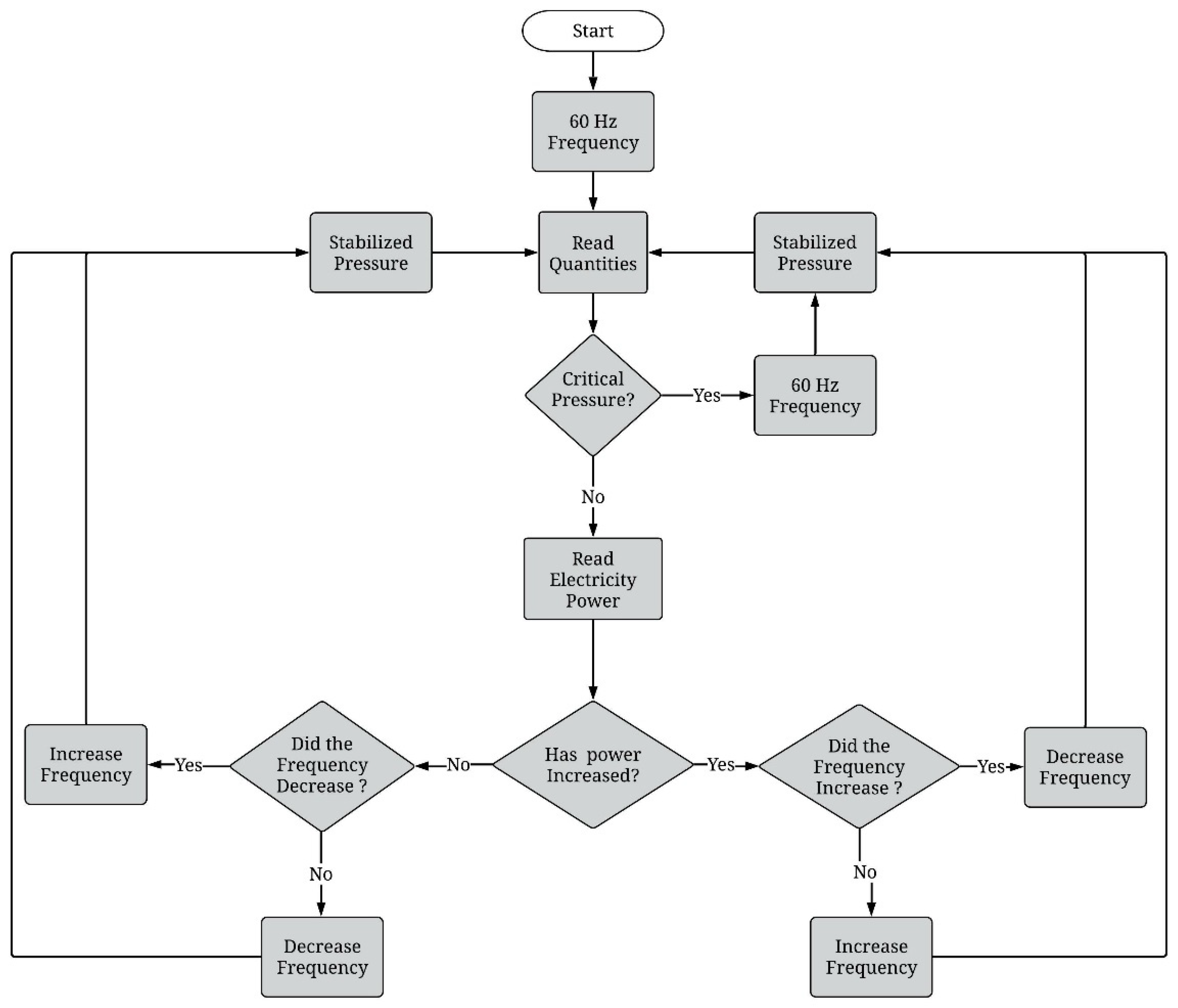
2.3. Modeling of the Logical Control

Environmental conditions are constantly changing, which affects the refrigeration system operation. Therefore, any manual intervention in the system probably would not lead to any energy savings. Thus, the use of some autonomous strategy, such as logical modeling, allows the achievement of continuous decisions to ensure the operation of the refrigeration system in a more efficient way.
The logical control modeling developed in this work consisted of the dynamic analysis of the variations suffered by the condensation pressure inside a refrigeration system. During a configurable period, taking the evaporative condenser pressure as a principal parameter, the model examined the possibility of modifying the rotation of the electric motors of the heat exchanger fans to increase or reduce the airflow rate in the device.
The dynamic modulation applied to the fan produced variations in the electrical power demands of the condenser and compressor. This change could initially modify the heat transfer rate rejected in the condenser, requiring a modification of the condensation pressure so that the thermal balance could be satisfied. These continuous modifications directly influenced the compression ratio pressure in which the compressor is operating.
The flowchart illustrated in Figure 3 shows the main steps explaining the logical control modeling work. At any instant of time, various monitored physical quantities were acquired using the measuring instruments connected to the PLC, such as the head condensation pressure, the suction pressure, the TDB, the TWB inverter frequency, and the electrical consumption. Next, these values were analyzed by the model and compared with the previously stored data from previous measurements. If the answer of the logical model was positive for modulation as a function of the previous air mass flow rate, the controller changed the frequency value to be transmitted to the electric motor of the fan. This new operating mass flow rate of air led the refrigeration system to a new thermodynamic equilibrium seeking to identify the point of the lowest electricity consumption.
The programming was developed using structured block language and scripts. The flowchart of the algorithm consisted of the following logical process steps:
  • Initially, it started the refrigeration facility with the airflow rate of the evaporative condenser (EC) at the maximum magnitude;
  • The model collected the operation data variables that were part of the process;
  • At this point, the condensation pressure value was changed. In this step, if the head pressure achieved a critical limit as previously established, logical control modeling improved the maximum mass flow rate of the air through the EC to reduce the pressure levels. At each pressure input, it was necessary to wait a required time interval for stabilization of the pressures and temperatures. The stabilization time is very important to the system to avoid impacts caused by the variation of the mass flow rate of the air. If the condensation pressure did not achieve a critical level, the logical model read the instantaneous consumed power and, at the same time, evaluated the magnitudes of the other stored quantities (condensation pressure and temperatures);
  • In case a reduction in the electricity consumption has occurred, the algorithm examined the last item in the database and identified whether there was a reduction in the frequency operation of electric motors of the fans. If positive, the algorithm decided to reduce the operation frequency again. If negative, the algorithm increased the frequency. An analog action occurs when the electricity consumption increases, i.e., if the previous action led to the increase in the operation frequency, the algorithm leads to the reduction in operation frequency of the fans; on the other hand, if the previous action led to reduction in the frequency, the new intervention reduces the rotation of the electric motors. In the present algorithm control, the frequency can be varied 5 Hz for each time step.
The logical control modeling works in an infinity loop, repeating readings, analyzing, and determining the operational decisions related to the mass flow rate of air through the EC, ensuring the system operates in a dynamic way based on the variations of the quantities presented during the process of refrigeration. These variables can be concerned with environmental conditions or those intrinsic to the interaction between the components of the refrigeration system.

3. Results and Discussion

3.1. Analysis of the Experimental Bench

We investigated a wide range of frequencies in the fans’ motors of the evaporative condenser. The volumetric flow rate of air through EC varied from 4.16 m3/s with successive reduction until the magnitude of 0.66 m3/s. Table 1 shows the values obtained for the electricity consumption in the refrigeration system (compressor and fans of condenser) and condensation pressure in the EC after the measurements on the experimental bench. The results showed that it is not necessarily beneficial for the refrigeration system to maximally reduce the magnitude of condensation pressure. For higher frequencies, there was a more significant gain of electric consumption in the fans driven motors than the reduction in consumption for to the lowest compression ratios in the compressor. On the other hand, for the lower frequencies, despite the lower consumption in the fans’ driven motors, the global consumption of the system (compressor and fans motors) was not reduced due to the augmentation of the power demand in the compressor. It is worth mentioning that parameters, such as thermal load and wet bulb temperature, were not used in the strategy of control of the developed algorithm and definition of operation frequency. Therefore, we used electric power for the logic control, which was the performance indicator considered in the refrigeration system. This parameter was chosen due to the commonly transient behavior of the ambient conditions and variation of thermal load by the product to be cooled, which makes difficult the use of other parameters as ambient information.
The results showed that the lowest volumetric flow rate of the air, Q = 0.66 m3/s, led to a power consumption of P = 2.51 kW. As the volumetric flow rate increased, the power consumption reduced up to the minimum magnitude of 1.81 kW for Q = 2.04 m3/s. From this point, the augmentation in the magnitude of Q led to an increase in electricity consumption up to the maximum magnitude of P = 3.19 kW, obtained when Q = 4.16 m3/s. The optimal volumetric flow rate of air was obtained for Q = 2.04 m3/s. This point of operation represented the condition where thermodynamic equilibrium (removing the unnecessary magnitude of thermal load out of the refrigeration system) and compression ratio that minimizes the consumption of the refrigeration system (compressor and fans of evaporative condenser) were obtained. The reason for this behavior was that for a volumetric flow rate of air above Q = 2.04 m3/s, there was a more significant gain of electric consumption in the fans’ driven motors than the reduction in consumption due to the lowest compression ratios in the compressor. On the other hand, for a volumetric flow rate of air lower than Q = 2.04 m3/s, despite the lower consumption in the fans’ driven motors, the global consumption of the system (compressor and fans motors) was not reduced due to the augmentation of the power demand in the compressor. This behavior occurred with the increase in the compression ratios and decrease in efficiency of the compressor for the lowest magnitudes of frequency of the control system.
For the range of values experienced, the lowest overall consumption was achieved when the EC fan operated at 49.0% of the maximum volumetric flow rate of the air. The consumption for this volumetric flow rate of air led to a measured consumption of 1.81 kW, which corresponded to a savings of 43.2% of the power consumed for the case with a maximum flow rate magnitude (4.14 m3/s). The results for the experimental bench indicated that the use of control modeling applied to the EC can be a superb strategy to save consumed energy in a refrigeration system. Despite this fact, it was important to investigate its application in an industrial case study. Parameters such as suction pressure, thermal load conditions, the refrigerant charge of the system, among others, are not significant to identify the validation of the present algorithm control, since the performance parameter itself (electric consumption) was measured for controlling of the refrigeration system. Thus, the refrigeration system was started and, during its operation, the frequency inverter of the fan motor of the EC was changed in the range from 25 to 60 Hz aiming to find the mass flow rate of air that led to the lowest power consumed.

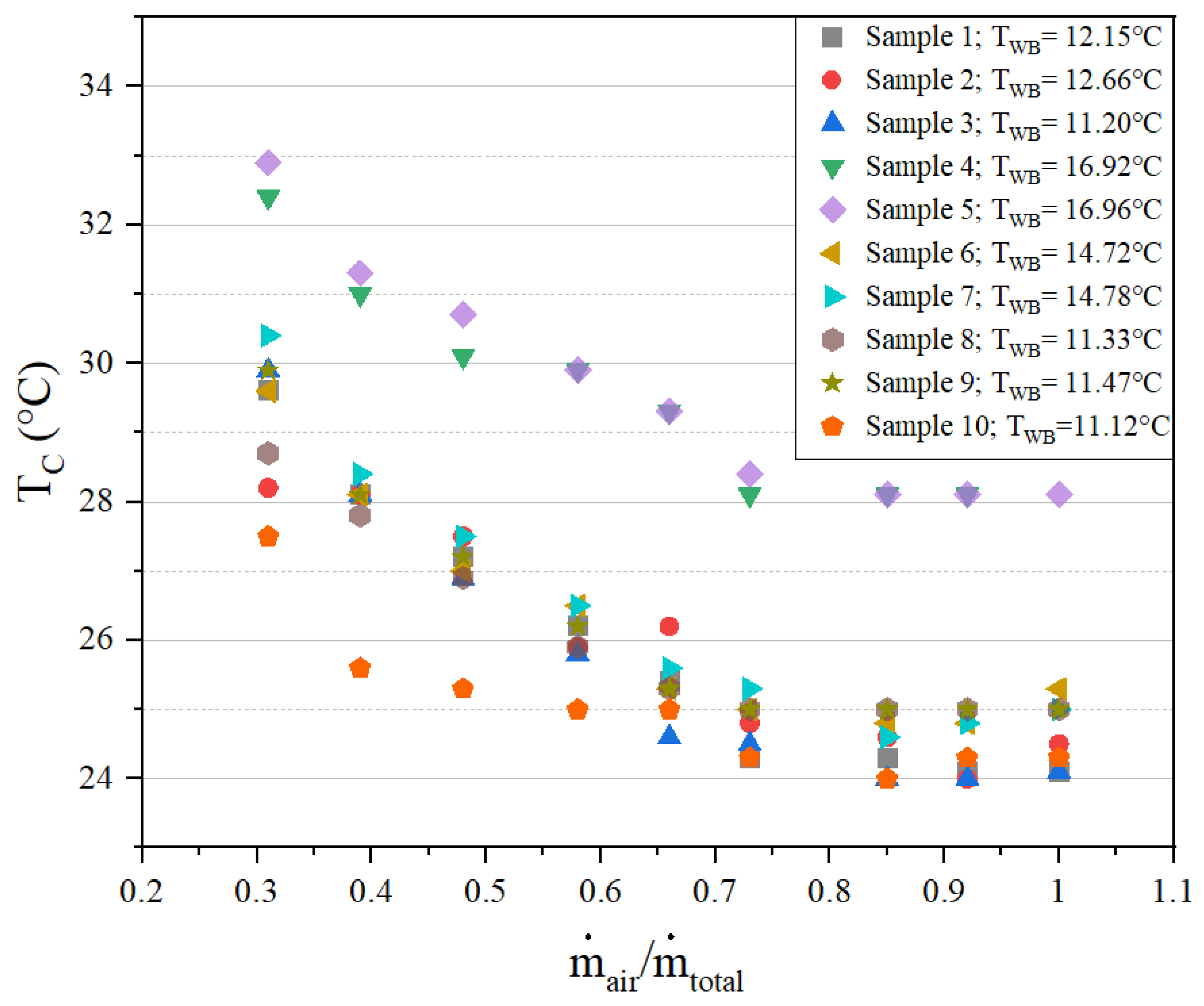
3.2. Analysis in an Industrial Refrigeration System

The electrical power and condensation pressure were monitored continuously in an industrial refrigeration system, accounting for 20 measurement samples.
The flow rate of air through EC has a fundamental role in the heat exchanger capacity. Higher fan rotations cause high volumetric flow rates of air and electricity consumption in the condenser. However, the heat and mass transfer coefficients are also increased, resulting in lower condensation pressures for the same thermal load to be rejected. Despite this fact, for a certain magnitude of the flow rate of air, the increase in its magnitude does not lead to a significant decrease in the condensation head pressure. This behavior occurs due to the approximation of the condensation pressure of the refrigeration system with that magnitude obtained for the wet bulb temperature of the external air. Thus, the heat exchanger significantly reduces its capacity. If the differences between the condensation temperature and the wet bulb temperature of the ambient air are very small, the increase in the mass flow rate of air may not significantly increase the influence of the EC heat transfer rate. Therefore, the operation of the fans with rotation greater than necessary (usually nominal) can lead to a waste of electrical energy.
Figure 4 demonstrates the behavior previously explained for 10 data samples acquired in the industrial refrigeration system under study. The results show that for the conditions of the wet bulb temperature and the thermal load tested, it was not possible to obtain condensation temperatures below 24 °C, even when the flow rate of the air of the condenser was at the maximum level.
For these samples, the best performance from an economic viewpoint was obtained when the ratio between the current air mass flow rate ( m ˙ air ) and the total air mass flow rate (air mass flow rate with a motor drive at a frequency of 60 Hz)— m ˙ air / m ˙ total —was in the range between 0.6 and 0.8. For magnitudes of the ratio m ˙ air / m ˙ total > 0.8, the results shown in Figure 4 indicated that an increase in the mass flow rate of air just caused waste of electricity, because it did not provide a significant reduction in the condensation pressure and, consequently, in the compression ratio. It is also possible to observe that each sample had a specific mass flow rate that corresponded to a minimum condensation pressure for the same system, demonstrating the importance of variable pressure condensation control.

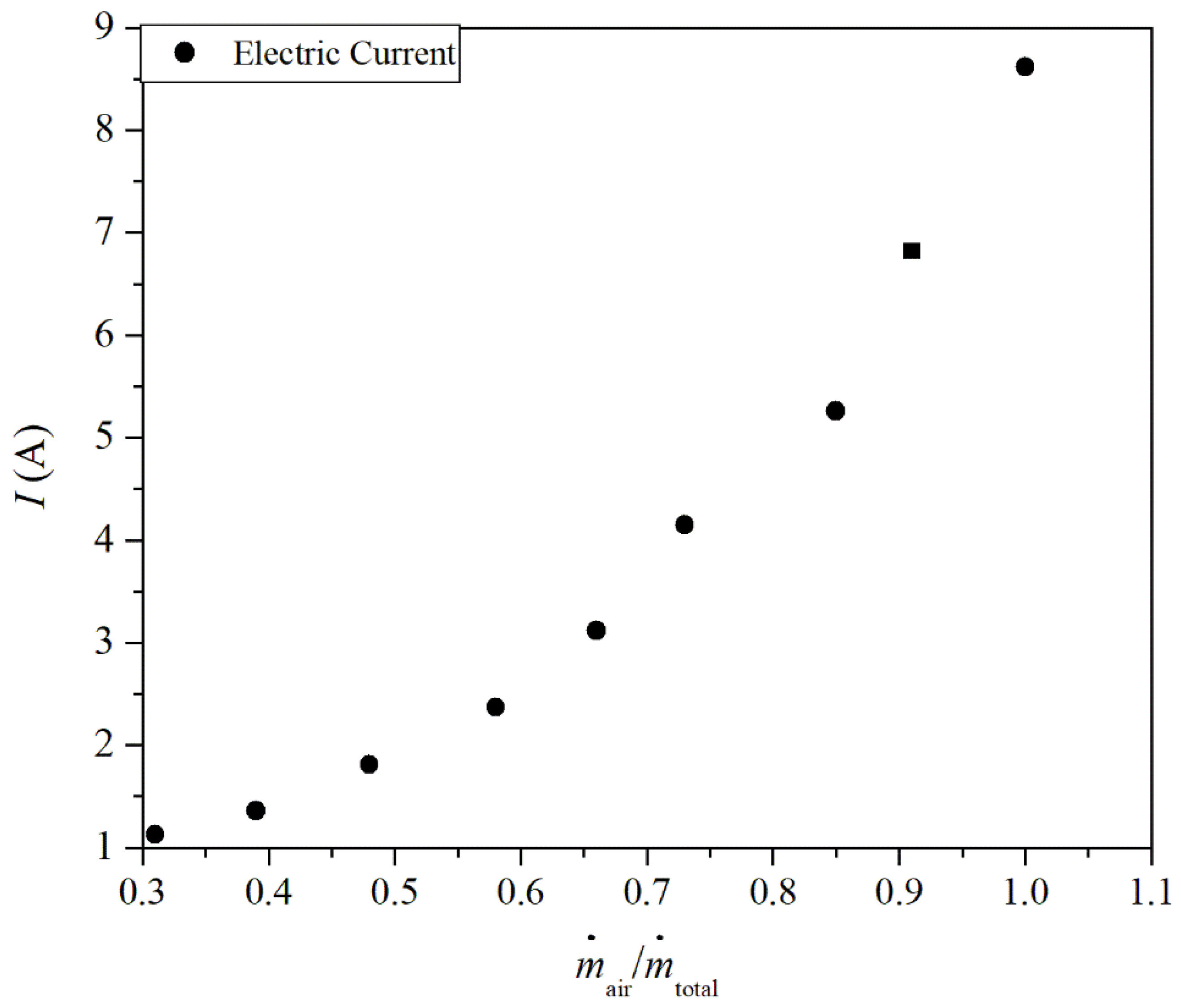
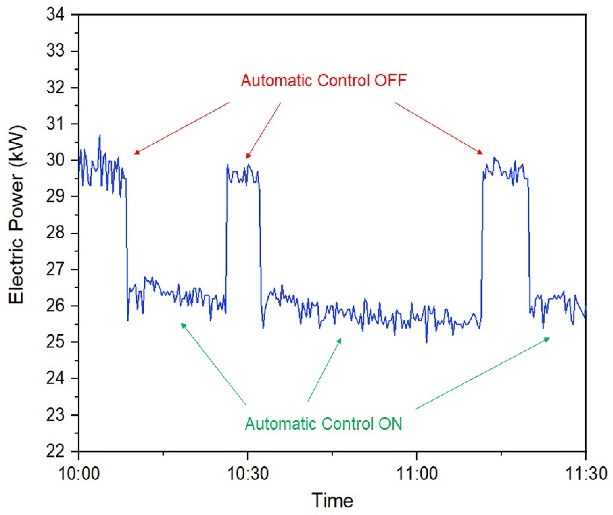
3.2.1. Electric Power Consumed by the Condenser

The initial condensation conditions existing in the industry unit investigated are the operation of the evaporative condenser with a nominal mass flow rate of air during all operating times of the refrigeration system. It is worth mentioning that the conditions found in the present study are normally the same in all other plants in the industrial refrigeration field. This situation represents the highest consumption of electricity by evaporative condenser fans, regardless of the variations that can occur during the thermodynamic process. When the condensation pressure was used as the operation parameter, the electric currents of the motors were found to generate the necessary mass flow rate of air to attend the refrigeration cycle and achieve the best overall energy efficiency of the plant. Table 2 shows the results of electrical current reduction as a function of nominal operation of the mass flow rate of air in the EC in an industrial refrigeration system. In that table, In represents the nominal electrical current (electrical current with fan drive motor at 60 Hz), while Ir refers to the electrical current of the fan drive motor at the frequency imputed by the pressure control system.
The results showed that when the refrigeration system operated with a reduced mass flow rate of the air in the EC, the decrease in the electric energy consumption by EC could reach a magnitude of 86.89%. Thus, it is possible to notice that, when the refrigeration system allowed a reduction in the magnitude of the mass flow rate of air in the EC to values lower than the nominal magnitudes, it was also possible to reduce the electricity consumption. Therefore, the use of modeling to control the pressure head in the EC proved to be an important strategy to save energy in real refrigeration plants, leading to a large economic savings each day.
Considering that other electrical parameters did not suffer from significant variation, an analysis could be performed in terms of the electric current consumed. Figure 5 demonstrates the variation in the electric current demanded by the EC fans as a function of the change in the mass flow rate of air. The change in electrical current caused by the variations in the mass flow rate ratio obtained here was in accordance with the expected behavior predicted by the fan laws. The results indicated that the increase in the mass flow rate of air also led to an increase in the electric current demanded by the EC fans, explaining the increase in the consumption of electric energy.
It is worth mentioning that the refrigeration system is a liquid overfeed system, the expansion valve is a low-pressure float valve, and it is placed at the inlet of the low pressure receiver (vertical separator). The expansion valve covers a large range of liquid flow rate, in general, until 1.5 times the nominal liquid flow rate. The condensation pressure of those valves also operates in a large range of magnitudes. Thus, the condensation pressure variations promoted by the FHPCC do not provide a significant change in the operation of the expansion valve.

3.2.2. Effects of the Interaction between the Compressor and the EC

Simultaneous analysis of the compressor and the EC allowed us to identify that a reduction in the mass flow rate of the air of the heat exchanger was not necessarily the aim in all situations. The reduction in the mass flow rate of air in the EC can result in an increase in the power demand of the compressor due to an elevation of the condensation pressure and, consequently, of the compression ratio and compressor electricity consumption. This behavior occurs because, when the mass flow rate of air decreases with a consequent reduction in electricity demand in the EC, there is an increase in the condensation pressure of the system. As a result, the compression pressure ratio increases, and consequently, an augmentation of electrical power in the compressor is necessary to supply the new demand. Therefore, there exists a point of minimal electric current consumption by the compressor and that required by the condenser, as shown in Figure 6 for four samples that better describes this behavior.
Table 3 shows the data from all measurements realized in an industrial system to verify the electric energy savings with modification of the EC mass flow rate of air. Thus, the values represent the electric power consumed by the EC and compressor. Therefore, it was possible to calculate the percentage of reduction in the overall electricity consumption in the whole refrigeration unit. Although the highest demand for electricity was related to the highest magnitudes of mass flow rate in the EC, it was not possible to define a fixed operating point for the EC fans that led to the lowest electric consumption. For the given studied conditions of the thermal load of the refrigeration system and the characteristics of the external environment where the evaporative condenser was placed, it would be necessary to modify the mass flow rate of air. The results also showed the largest difference of 11.36% for Sample 14, which indicates that for some determined conditions of the refrigeration system, the gain from the use of FHPCC can be significant.
One other important aspect is that we did not find a direct relation between the magnitude of TWB and the consumption of the electric power in the present investigation. For each flow rate of air investigated, a different energy consumption was verified, even with similar magnitudes of TWB measured during the experiments. Additionally, for each day, the refrigeration systems operated at different conditions, e.g., the thermal load, schedule of defrost, and amount of ammonia gases that were not condensed. These parameters also had an influence on the energy consumption of the refrigeration system, precluding the proper definition of the influence of TWB over the demanded power of the compressor and evaporative condenser. Therefore, the logical control used as its parameter the power of the system, regardless of the TWB and operational conditions found during the experiments, it was possible to obtain the influence of the flow rate of air over the power of the system.
To summarize, a real-time investigation in industry operation was conducted with the objective of validating the developed logical model. In the observation period, represented in Figure 7, the refrigeration system had its operation divided between the situation where the FHPCC was acting (identified as automatic control on) and simple operation without any control and considering the maximum mass flow rate of air (identified as automatic control off). Figure 7 shows the electricity consumption variations of an industrial refrigeration unit for two different conditions: (1) when the logical model (FHPCC) was in operation and (2) when the operation was suspended. When its operation was suspended, there was a clear increase in the electric energy demand. Immediately after the logical model returned to automatic operation control, the consumption of electricity was reduced again. Therefore, a percentage reduction of nearly 10% was achieved in the studied system, i.e., this behavior proves the real economy of electric energy when the refrigeration system uses FHPCC.

4. Conclusions

The present study showed how dynamic control modeling of an evaporative condenser, using a floating operation of the condensation pressure, can rationalize the consumed electric energy in an industrial vapor compression refrigeration system. More precisely, the control of the condensation temperature was obtained by varying the values of the mass flow rate of air in the EC using VSD in the motor fans of the heat exchanger.
Initially, the effects were evaluated in an experimental bench to be implemented in an industrial refrigeration unit that uses ammonia as a refrigerant fluid. In the experimental bench, the electricity consumption depended on the mass flow rate of the air in the EC.
Based on the collected data during the experimental process, a logical model was developed to control the condensation head pressure and its automatic variations. After the execution of the tests, simulating different operation conditions of the bench, the logical model was validated. During the validation, a reduction of 43% in the total demand for electricity was observed when the system with control and the system without control (considering the mass flow rate of air in the evaporative condenser fans operating in the nominal condition) were compared.
Implementing the same logical model in an industrial unit, i.e., an ammonia refrigeration system, the results showed that the developed control modeling had significant improvements in the consumption of electric current. The results presented an average reduction of 7.5% and had the highest reduction of 11.36% in the electrical power demand by the refrigeration equipment. The results also recommended the use of intermediate mass flow rates of air in the evaporative condenser for the studied conditions. The superior extreme of the mass flow rate of air in the EC led to a high consumption of energy by the EC fans to drive the air, while the inferior extreme led to an augmentation of condensation pressure, overloading the compressor of the refrigeration system.
To summarize, the results obtained here demonstrated that the use of FHPCC can be a promising solution to reduce the consumption of energy in an actual industrial refrigeration system, set in the context that electricity costs to run refrigeration units are very high. Moreover, the implementation of the programming logic can be extrapolated for other refrigerant systems considering the particularities of each unit. It is worth mentioning that, due to a wide amount of equipment of different manufacturers in an industrial refrigeration unit, a universal logic that meets all situations is impractical. Despite this, the conceptual aspects developed here can be used in other units, leading to important energy savings in most of the industrial refrigeration systems.

Author Contributions

Conceptualization, F.L.d.C.C. and I.C.A.J.; methodology, F.L.d.C.C., D.B.A. and I.C.A.J.; formal analysis, C.B., D.B.A., E.D.d.S. and I.C.A.J.; investigation, F.L.d.C.C. and D.B.A.; resources, C.B., E.D.d.S. and I.C.A.J.; data curation, F.L.d.C.C. and I.C.A.J.; writing—original draft preparation, D.B.A., E.D.d.S. and I.C.A.J.; writing—review and editing, C.B. and E.D.d.S., visualization, C.B., E.D.d.S. and I.C.A.J.; supervision, E.D.d.S. and I.C.A.J.; project administration, C.B., E.D.d.S. and I.C.A.J., funding acquisition, C.B., E.D.d.S. and I.C.A.J. All authors have read and agreed to the published version of the manuscript.

Funding

This research was funded by the Italian Ministry for Education, University and Research, National Council for Scientific and Technological Development—CNPq and Research Support Foundation of the State of Rio Grande do Sul—FAPERGS. C. Biserni is sponsored by the Italian Ministry for Education, University and Research. E.D. dos Santos thanks CNPq (Brasília, DF, Brazil) for the research Grant (Process: 306024/2017-9). All authors thank FAPERGS for financial support in PqG Program—Notice No. 05/2019 (Process: 19/2551-0001847-9).

Data Availability Statement

The data to support the findings of this study are available from the authors upon request.

Acknowledgments

The authors thank the Federal Education Science and Technology Institute of Rio Grande do Sul (IFRS), Federal University of Rio Grande (FURG), and University of Bologna (UNIBO) for support in the research.

Conflicts of Interest

The authors declare no conflict of interest. The funders had no role in the design of the study; in the collection, analyses, or interpretation of data; in the writing of the manuscript, or in the decision to publish the results.

Nomenclature

Parameters
PnNominal powerkW
PmMeasured powerkW
VVelocitym/s
m ˙ air Mass flow rate of the airkg/s
m ˙ total Mass flow rate of the air in the nominal conditionkg/s
TTemperature°C
TDBDry bulb temperature°C
TWBWet bulb temperature°C
TCCondensation temperature°C
PPressurebar
URRelative humiditybar
PoverallOverall electrical powerkW
qrejHeat transfer rate rejection in the evaporative condenserkW
PmotorMotor electrical powerkW
PminMinimum electrical powerkW
PmaxMaximum electrical powerkW
Abbreviations
COPCoefficient of performance
CPCompressor
ECEvaporative condenser
FHPCCFloating head pressure condensation control
HVACHeating, ventilation, and air conditioning
OCPOperation condensation pressure
PLCProgrammable logic controller
VSDVariable speed drive
DiffDifference

References

  1. World Electricity Final Consumption by Sector, 1974–2017—Charts—Data & Statistics, IEA. Available online: https://www.iea.org/data-and-statistics/charts/world-electricity-final-consumption-by-sector-1974-2019 (accessed on 9 January 2021).
  2. Chen, B.; Wang, Y.; Wang, R.; Zhu, Z.; Ma, L.; Qiu, X.; Dai, W. The Gray-Box Based Modeling Approach Integrating Both Mechanism-Model and Data-Model: The Case of Atmospheric Contaminant Dispersion. Symmetry 2020, 12, 254. [Google Scholar] [CrossRef] [Green Version]
  3. Máša, V.; Touš, M.; Pavlas, M. Using a utility system grey-box model as a support tool for progressive energy management and automation of buildings. Clean Technol. Environ. Policy 2016, 18, 195–208. [Google Scholar] [CrossRef]
  4. Manske, K.A.; Reindl, D.T.; Klein, S.A. Evaporative condenser control in industrial refrigeration systems. Int. J. Refrig. 2001, 24, 676–691. [Google Scholar] [CrossRef]
  5. Lu, W.; Meng, Z.; Sun, Y.; Zhong, Q.; Zhu, H. Improved energy performance of ammonia recycling system using floating condensing temperature control. Appl. Therm. Eng. 2016, 102, 1011–1018. [Google Scholar] [CrossRef]
  6. Chan, K.T.; Yu, F.W. Applying condensing-temperature control in air-cooled reciprocating water chillers for energy efficiency. Appl. Energy 2002, 72, 565–581. [Google Scholar] [CrossRef]
  7. Yu, F.W.; Chan, K.T. Modelling of the coefficient of performance of an air-cooled screw chiller with variable speed condenser fans. Build. Environ. 2006, 41, 407–417. [Google Scholar] [CrossRef]
  8. Aprea, C.; Mastrullo, R.; Renno, C. Fuzzy control of the compressor speed in a refrigeration plant. Int. J. Refrig. 2004, 27, 639–648. [Google Scholar] [CrossRef]
  9. Aprea, C.; Mastrullo, R.; Renno, C. Experimental analysis of the scroll compressor performances varying its speed. Appl. Therm. Eng. 2006, 26, 983–992. [Google Scholar] [CrossRef]
  10. Karunakaran, R.; Iniyan, S.; Goic, R. Energy efficient fuzzy based combined variable refrigerant volume and variable air volume air conditioning system for buildings. Appl. Energy 2010, 87, 1158–1175. [Google Scholar] [CrossRef]
  11. Pinnola, C.F.; Vargas, J.V.C.; Buiar, C.L.; Ordonez, J.C. Energy consumption reduction in existing HVAC-R systems via a power law controlling kit. Appl. Therm. Eng. 2015, 82, 341–350. [Google Scholar] [CrossRef]
  12. Yu, F.W.; Ho, W.T.; Chan, K.T.; Sit, R.K.Y. Logistic regression-based optimal control for air-cooled chiller. Int. J. Refrig. 2018, 85, 200–212. [Google Scholar] [CrossRef]
  13. Mcquiston, F.C.; Parker, J.D.; Spitler, J.D. Heating, Ventilating, and Air Conditioning: Analysis and Design; John Wiley & Sons: Danvers, MA, USA, 2005. [Google Scholar]
  14. Schibuola, L.; Scarpa, M.; Tambani, C. Variable speed drive (VSD) technology applied to HVAC systems for energy saving: An experimental investigation. Energy Procedia 2018, 148, 806–813. [Google Scholar] [CrossRef]
  15. Saidur, R.; Mekhilef, S.; Ali, M.B.; Safari, A.; Mohammed, H.A. Applications of variable speed drive (VSD) in electrical motors energy savings. Renew. Sustain. Energy Rev. 2021, 16, 543–550. [Google Scholar] [CrossRef]
  16. Al-Bassam, E.; Alasseri, R. Measurable energy savings of installing variable frequency drives for cooling towers’ fans, compared to dual speed motors. Energy Build. 2013, 67, 261–266. [Google Scholar] [CrossRef]
  17. Yu, F.W.; Ho, W.T.; Chan, K.T.; Sit, R.K.Y.; Yang, J. Economic analysis of air-cooled chiller with advanced heat rejection. Int. J. Refrig. 2017, 73, 54–64. [Google Scholar] [CrossRef]
  18. Acunha, I.C.; Schneider, P.S. Consolidated experimental heat and mass transfer database for a reduced scale evaporative condenser. Int. J. Refrig. 2016, 66, 21–31. [Google Scholar] [CrossRef]
Figure 1. Schematic representation of the experimental bench.
Applsci 11 11923 g001
Figure 2. Divisions of the air intakes of the industrial refrigeration unit of the evaporative condenser for the measurements of the inlet velocity.
Applsci 11 11923 g002
Figure 3. Flowchart of the developed logical model of control.
Applsci 11 11923 g003
Figure 4. Variation of condensation temperature as a function of the mass flow rate of air.
Applsci 11 11923 g004
Figure 5. Variation of the electric current demand by the fan motor of the evaporative condenser as a function of modification of operating rotation.
Applsci 11 11923 g005
Figure 6. Variation of electrical power of the fans’ motors of the evaporative condenser as a function of mass flow rate of air.
Applsci 11 11923 g006
Figure 7. Impact of the performance of the logical model on electricity consumption.
Applsci 11 11923 g007
Table 1. Electricity consumption of the experimental bench.
Frequency
(Hz)
Volumetric Flow Rate of the Air (m3/s)Consumption CP + EC (kW)Condensation Pressure (bar)
504.163.1910.53
453.742.9210.59
403.222.6610.72
352.802.5010.92
302.422.3611.08
252.041.8110.58
201.591.8511.42
151.142.4113.22
100.662.5114.44
Table 2. Current electric reduction with modification of the air mass flow.
m ˙ air / m ˙ total Pn (kW)Pm (kW)Difference (%)
1.001.891.890.00
0.921.891.5120.88
0.851.891.1638.98
0.731.890.9251.86
0.661.890.6963.81
0.581.890.5272.51
0.481.890.4079.00
0.391.890.2984.22
0.311.890.2486.89
Table 3. Overall compressor and condenser electrical power demands.
SamplePmin
(kW)
Pmax
(kW)
TWB (°C)Diff. %SamplePmin
(kW)
Pmax
(kW)
TWB (°C)Diff.
%
136.9738.988.65.181134.7537.2311.36.66
238.3340.9912.26.481235.0537.2011.45.77
337.3339.7512.76.101334.0038.3111.111.25
435.0537.1611.85.691433.8438.1811.011.36
536.0038.5811.26.701535.2838.9213.39.35
635.5738.5511.37.731636.2139.2113.57.66
733.9936.168.96.011736.4439.6213.68.02
833.9235.898.65.491838.0941.3516.97.88
936.5740.4614.79.631938.0140.8417.06.91
1036.7739.8914.77.822037.8141.2117.08.25
Publisher’s Note: MDPI stays neutral with regard to jurisdictional claims in published maps and institutional affiliations.

