Article

Structure and Mechanical Properties of the Dueñas Clay Formation (Tertiary Duero Basin, Spain): An Overconsolidated Clay of Lacustrine Origin

by
José Nespereira
1,*,
José Antonio Blanco
1,
Mercedes Suárez
1,
Emilia García-Romero
2,3,
Mariano Yenes
1 and
Serafín Monterrubio
1
1
Department of Geology, University of Salamanca, 37008 Salamanca, Spain
2
Department of Mineralogy and Petrology, Complutense University of Madrid, 28040 Madrid, Spain
3
Geosciences Institute (IGEO) Spanish Research Council and Complutense University (CSIC-UCM), 28040 Madrid, Spain
*
Author to whom correspondence should be addressed.
Appl. Sci. 2021, 11(24), 12021; https://doi.org/10.3390/app112412021
Submission received: 12 November 2021 / Revised: 10 December 2021 / Accepted: 12 December 2021 / Published: 17 December 2021
(This article belongs to the Special Issue Engineering Geology of Clay and Clay Soils)

Abstract

:
The Dueñas Clay Formation is considered an example of a deposit of lacustrine continental origin. It is formed mainly by overconsolidated clays and includes feldspathic arenites, and clayey and silty levels; however, in geotechnical projects it is considered a clay unit and treated as a whole. The structure of each level was assessed in the field, in thin sections, and by SEM in the case of the clayey level. In addition, identification, strength, deformation, and durability tests were undertaken according to the nature of the samples (grain size analysis, Atterberg Limits, point load test, direct shear tests, uniaxial compression tests, swelling pressure, and unidimensional consolidation tests). The durability test was used as a criterion for dividing the levels within the formation according to their behavior as soil or rock. It was observed that the proportion and type of carbonate cementation controls the way in which the material behaves, with sparithic cement increasing the strength. The clay levels are expansive due to the presence of smectite, which also influences their behavior under shear stress. In addition, the massive and laminar structure of the layers caused by the continental conditions, in addition to the processes of post-sedimentation, explain their low compressibility.

1. Introduction

Overconsolidated clays (OCs) do not have particularly poor mechanical properties but their discontinuities and cementations, in addition to the difficulties in defining realistic behavior models [1,2], justify their study. Many OCs have been studied in soil mechanics, but most of these were sedimented within geological contexts defined by marine basins [3,4,5,6,7,8,9,10,11]. As such, the references for those OCs of continental origin are scarce and mostly focus on Pleistocene Italian clays [12,13,14,15,16]. A common feature of all these clays is that their geomechanical behaviors depend on their structural configurations, and these are the results of their geological histories.
Marine and continental overconsolidated clays (MOCs and COCs, respectively) share common geological episodes, such as sedimentation, consolidation, bioturbation, erosion, diagenesis, and tectonic activity, all of which are included in the Geotechnical Cycle [15]. However, when the properties that differentiate them are taken into account, such as water composition, sedimentation rates, air exposure time, crusting processes, or cracking desiccation, is the geomechanical behavior the same? In addition, are their structures similar and what is the effect of the geological history?
This study was focused on the Cenozoic Duero Basin in Spain, a place where significant civil engineering works are undertaken on lacustrine clayey facies with predominant overconsolidated clay levels. Most often, these clays are all included within the same geotechnical clayey level [17]. In this work, the Dueñas Clay (DC) Formation was selected; sedimented in a lacustrine environment [18], it is one of the most affected by the construction works at this area [19]. The field description of the outcrop selected, and the durability tests carried out with samples from each identified level, allowed the behavior of the rock and soil material in this formation to be determined. All the materials were petrographically described, and special attention was paid to their microstructure and, where necessary, their macrostructure features. Special attention was paid to the clay levels, because their properties usually condition the geotechnical analyses in which the DC Formation is involved [20]; in addition, its reconstituted state was also studied [14] under unidimensional compression, which is a useful framework for comparing the effects of geologic history on the clays and for creating constitutive models for structured soils [21].

2. Geological Setting

The clayey levels of lacustrine origin are predominant in the central area of the Duero Basin, Ref. [22] (Figure 1). They appear as a sequence of siliciclastic and carbonated sediments comprising major units called facies. According to the classic classification of Hernández Pacheco (1915) and following ideas similar to those of [18,22], among others, four facies can be distinguished from bottom to top: Dueñas, Tierra de Campos, Cuestas, and Páramo (Figure 1). Their distinct colors—green, brown, and whitish gray for Dueñas, Tierra de Campos, and Cuestas, respectively—their subhorizontal disposition, and the tabular morphology of the Paramo, allow them to be easily identified.
The Ramblian–Aragonian (Lower Miocene) Dueñas facies (Alonso-Gavilán, op.cit) includes clays, marls, limestone, and diagenetic gypsum in some locations, and has been interpreted as a lacustrine deposit with gypsum episodes. It is the basal Miocene unit for the center of the Duero Basin and so, above it overlaid all the following facies, which have been eroded in an important area causing the overconsolidated state in the Dueñas facies.

3. Materials and Methods

An outcrop located in the surrounding area of Arroyo de la Encomienda (Valladolid, Spain) was selected for describing and sampling the Dueñas Formation. Although its thickness is low, it contains the main features of the facies and it can be sampled easily. Small block fragments were obtained from the slope surface for identification tests, and mineralogic and petrographic descriptions. Undisturbed block samples 30 cm × 20 cm × 15 cm were recovered for strength and deformability tests by digging two parallel trenches with the aid of a hydraulic excavator and leaving a bench between. The final dimensions of the blocks were shaped using manual spades and a soil saw. Once isolated, they were wrapped in transparent film, placed in wooden boxes, and protected with polyurethane foam injected between the samples and the boxes.
The semiquantitative mineralogical content was determined by X-ray diffraction analysis (using the BRUKER D-8 Advance diffractometer equipped with Cu Kα radiation, at the X-ray Diffraction Service of the University of Salamanca) of total rock and the <0.002 mm fraction (oriented aggregates, OA, and samples solvated with ethylene-glycol, EG).
Thin sections were obtained from samples on each of the levels identified in the outcrop and observed under petrographic microscopy (Leica DM2500P optical microscope under transmitted light at the Geodynamics Department of the University of Salamanca), enabling their description and classification considering [23,24].
Because structure is one of the factors that determines the mechanical response of the soils, the most significant characteristics across the various levels were described. The term structure is used in this article to define fabric and bonding, where the former is the arrangement of the component solid particles, and bonding refers to the interparticle forces which are not of a purely frictional nature [25,26]. Depending on the scale in which the observations are made, macrostructure is used to refer to features observable to the naked eye, and microstructure for the remainder.
Regarding the microstructure, petrographic and electronic microscopy observations were carried out, the latter only for the clayey levels at the bottom. The clay levels were also studied through scanning electron microscopy (SEM). The surfaces selected were obtained after fracturing the slope surface sample. They were air-dried, and after the surfaces were peeled, embedded with a thin film of a conductor.
The orientation of the planar macrostructure features observed in the outcrop were measured using a geological compass. On the clay levels, the discontinuities can be classified as laminations, fissures, and joints [6]; laminations are characterized by a thin layer of a siltier material and would be equivalent to the bedding; the fissures are considered small fractures within a lithological level, not crossing its boundaries; and, finally, the joints are important fractures that are predominantly vertical.
In geotechnical projects, the DC Formation is usually treated as a unique engineering geological unit (EGU), considering that all the materials have uniform physical and lithological properties [20]. Nevertheless, from the geotechnical point of view, and after describing all the levels, this characterization can be improved, because there seems to be rock and soil materials in the facies. The discretization between soils and rocks is a simple and useful criteria to be applied on the DC Formation, although there are different ways to address it. Ref. [20] established that all terrains with uniaxial compression strength higher than 1 MPa should be considered as rocks. By comparison, soil is considered in [27] as natural aggregates of particles separable by low energy mechanical means or by agitation in water, and this criterion was adopted for identifying the rock and soil levels within the DC Formation. Although the testing program was focused on the clay levels, the strength, physical properties, and carbonate content in the rock levels were also studied. Following the methods suggested in [28], grain size analysis, liquid and plastic limit determination, direct shear and uniaxial compression strength tests, and finally, standard unidimensional consolidation tests, were carried out. Concerning the direct shear tests, samples 50 mm in diameter and 25 mm thick were tested under undrained conditions. Five samples were tested under vertical effective stresses of 98 (1), 196 (2), and 392 (2) kPa, and the shear finished for 5 mm horizontal displacement or more. As this study analyzed the effects of geological processes on mechanical behavior, the intrinsic properties of the clays from the DC Formation were considered to construct a frame for evaluating the compressibility of the natural samples. For this purpose, reconstituted samples were prepared following the procedure described in [14], and then the unidimensional consolidation test was carried out.
A simple semi-quantitative test was used to analyze the durability of each level when submerged in water, based on the Jar Slake Test recommended by [3,29,30], among others. Small fragments were submerged in distilled water for 24 h, and the changes observed were noted and compared to the initial dry mass of each fragment tested. After immersion, each of the laboratory containers used were emptied onto a 2 mm sieve; the retained fragments were considered undamaged if they maintained their shape after applying slight pressure with a finger. The process was repeated twice for each level.
Finally, density and strength using the point load test were examined on the rock samples [28]. The point load test was selected as an index method, which is useful when the natural conditions of the samples impede the preparation of cylindrical samples [31,32].

4. Results

4.1. Description and Mineralogy

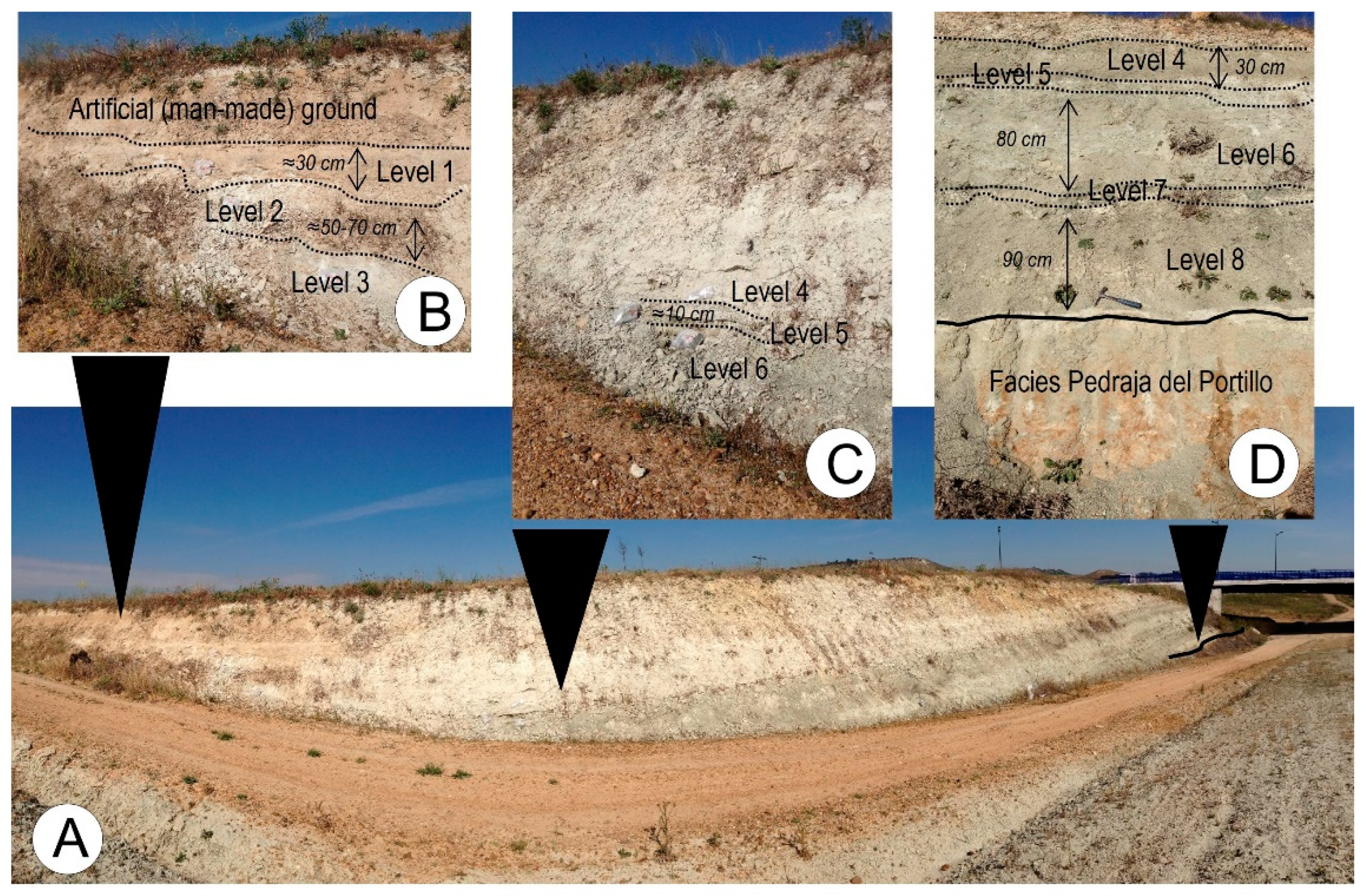
The selected outcrop (Figure 2A) is a section with a depth of four meters with a thin coated cemented sandy level at the bottom, and a quaternary colluvial deposit or artificial (man-made) ground deposits at the top (Figure 2B). Its top is at an altitude of 730 m.a.s.l, whereas the top of the tertiary facies reaches 850 m.a.s.l. Therefore, erosion of no less than 120 m can be deduced. In the lower part of the section, two clayey and silty levels can be identified: level 8 and level 6 (Figure 2C,D). They are green-colored, plastic, stiff clays, up to one meter thick, with a coarse sand level between them (level 7). At the top, high-competence and continuous layers appear at level 1, level 3, and level 5 (Figure 2B). They are ten to thirty centimeters thick, showing among them two silty sand levels—level 2 and level 4—on which some discontinuities can be observed.
The XRD analysis indicates the presence of phyllosilicates, quartz, calcite, dolomite, and alkali feldspar. On the oriented aggregates, smectite, illite, and palygorskite were identified in the clay fraction (Table 1).

4.2. Structure

4.2.1. Macrostructure

The most evident macrostructure is the bedding that binds the most competent levels at the top of the outcrop, level 1, level 3, and level 5. It is undulated and plane, with a rough surface and spacing ranged between 20 and 60 cm (Table 2).
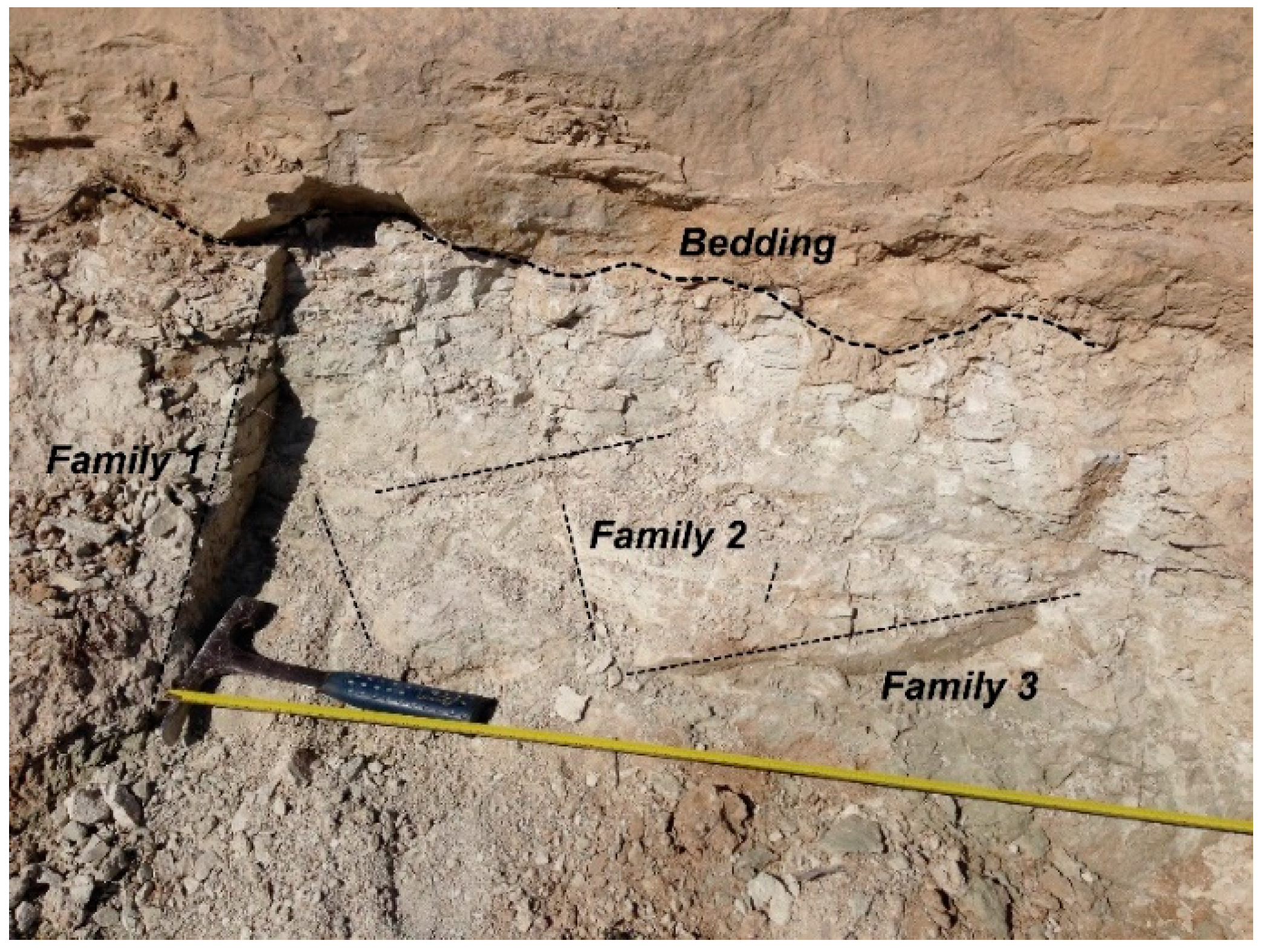
In level 2, up to three families of discontinuities were identified, all of which are vertical and with similar features: continuity from 1 to 3 m, spacing of 20 to 60 cm, and interrupted nearly to the upper and lower levels, without appearing in the cohesive levels at the lower part of the facies (Table 2 and Figure 3). The orientations measured, ranging from 240° and 270° (strike) in one case and practically N–S in the other, partially match the stream courses and some sections of the current Pisuerga riverbed near the outcrop. According to [33,34], these orientations are due to the late-alpine orogenic processes.

4.2.2. Microstructure

The thin sections studied under petrographic microscope can be divided into feldspathic arenites, sandy lutites, silicate sands, and silicate clays.
  • Feldspathic arenite (level 1, level 2, level 4, and level 5)
These levels appear at the top of the outcrop, sometimes laminated and containing the remains of ostracods (Figure 4A,B). Their skeleton’s clasts are mainly quartz, although feldspar can also be seen, with sizes ranging from 0.06 mm to 0.1 m and subangulous morphologies, frequently corroded at their edges due to the action of the carbonate cementation. Micaceous straws are occasionally identified. Pelloids or spheroidal masses of calcareous-micrite nature, similar in size to those of quartz grains, may also be considered as clasts, and react with calcareous limestone cementum. The whole skeleton is joined by a matrix of equal composition, but practically obliterated by a micrite or microsparite mosaic of carbonate crystals, showing a lighter color than the micrite of the pelloids.
Regarding the arrangement of the solid particles, the lamination observed is created by the vertical alternation in grain sizes (Figure 4A), a common feature in lake deposits frequently associated with seasonal precipitation of carbonates or with periodic influxes of sediment into lakes [35]. In this case, sometimes the lamination appears interrupted by carbonate nodules that partially or totally replace previous grains and the matrix with a dark micrite (Figure 4A). These nodules have varied sizes, from 0.1 to several millimeters, and present round to sub-round morphologies. They are associated with post sedimentary processes, where the larger ones are visible to the naked eye. Inside them, only strongly birefringent clay remains.
Finally, some fossil content (ostracods) appears as straws oriented parallel or subparallel to bedding, resembling the micas.
  • Sandy carbonated lutite (level 3)
This is a sandy carbonated lutite, with developed processes of carbonate crust. The largest clasts, between 0.2 and 1.5 mm, are quartz and feldspar having poorly rounded morphologies. The matrix is entirely clayey and is reorganized with the formation of birefringent domains, adopting highly variable geometries (grain-striated, parallel, porous-striations, and reticulated and cross-reticulated striations) (Figure 4C,D). The incipient crusting is shown by the replacement of clay material by a dark micrite mass, forming nodules.
  • Clay (level 6 and level 8)
Clays with sandy clasts and unevenly developed carbonate crusts (Figure 4E,F), with some micas in the shape of straws were occasionally observed. Carbonate cement corrodes the previous clasts, the ostracods—only present in the areas where the crust is smaller—and the micritic pelloids that appear. After the crusting process, a bioturbation was developed in the crust creating holes that were filled by sand-size particles (Figure 4G). Some microstructures or reorientation of the S-matrix type were observed.
  • Silicate sand (level 7)
This is a silicate sand with no cohesion among its particles. The sizes of the clasts range between 0.4 and 1 mm, and present sub-rounded to slightly rounded morphologies; quartz and feldspar were mainly identified, although fragments of quartzite with occasional sizes up to 4 mm were found, in addition to occasional micas in the form of straws and some tourmalines.
The skeleton is surrounded by a clayey-silty matrix with evidence of post-sedimentation processes, such as the reorganization of the clay component around the biggest grains, which caused a systematic birefringent surrounding boundary (Figure 4H). It is a grain-striated b-fabric [24], and it is usually related to post-sedimentation edaphic activity [36].
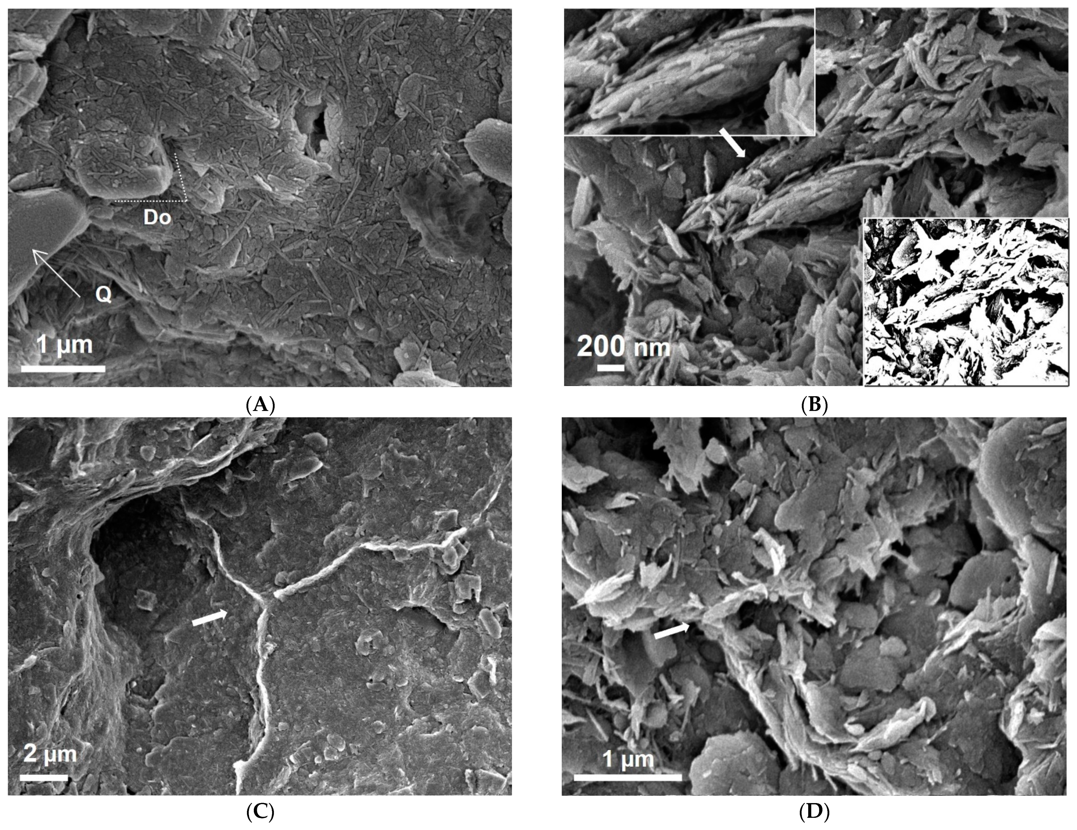
The general view observed under scanning electron microscopy displays a massive and laminar texture due to the presence of an oriented clayey plasma (Figure 5A) caused by a well-dispersed material sedimentation. The lamination is defined by the subparallel disposition of the laminar (illite and smectite) and fibrous (palygorskite) particles. The bigger particles are quartz and feldspar. The presence of a small amount of dispersed dolomite crystals of approximately 0.5–1 µm, covered by sedimentary particles, indicates the sedimentary origin of this mineral. In the clayey plasma some small palygorskite crystals appear, between 0.2 and 0.7 µm. This mineral is easily identified by its fibrous morphology. The fibers are not forming boundless, as normally occurs in sedimentary palygorskite [37], but appear as laths (individual crystals), indicating that this mineral was in the original suspension, deposited as detrital particles and not by chemical precipitation.
The texture corresponds to a stacked-type dispersion structure, with domains defined by overlapping face-to-face (Figure 5B) contacts and no flocculation traits are observed. The porosity can be intercrystaline and interparticle, and ranges between 100 nm and 10 μm in size (Figure 5B,C), with the biggest showing a predominant circular morphology. It highlights the appearance of a particular textural feature in some zones in which the clay minerals are almost vertically oriented, perpendicular to the sedimentary surface defining plains that coalesce in a “triple point” (Figure 5C,D). These unique features are caused by the reorientation of clay-plate domains in the process of water loss after the sedimentation.

4.3. Density, Carbonate Content, Durability and Rock Strength

The dry density shows a decreasing trend from top to bottom, where the clay levels predominate and where the lower values were obtained as 1.65 Mg/cm3. On the rocky levels, the values range from 2.00 to 2.31 Mg/m3, with the highest values on level 1, feldspathic arenite, and the lowest in level 3. In addition, the porosity ranged from 13 to 24%, displaying an inverse correlation with the density (Table 3).
From the carbonate content obtained from the Bernard calcimeter tests, it was clear that the highest values were located at the top, decreasing towards the bottom of the column (Table 3).
Two groups were formed using the results obtained: the levels that collapsed very little or not at all (collapsed mass ≤10%), and those that completely collapsed (Table 3).
Levels 1, 2, 3, and 5 behaved as rocks since they were scarcely or not at all affected when submerged in water. Frequently, insignificant amounts of material were lost from the surface of the samples, but did not exceed 2%, except for level 2, which was less competent than the other rocky levels according to the field observations, and lost 9%.
The samples from levels 4, 6, 7, and 8 completely collapsed and, therefore, they were considered as soils. Nevertheless, there were some differences between the levels described as cohesive and granular: in the former, the process of collapse was gradual, but in the granular level, level 7, it happened immediately after being submerged. This indicated that the cohesive forces between the particles were controlled by suction, which was reduced as soon as immersion took place.
According to the point load test results, the rocks within the DC Formation were soft, and although the differences were not very significant, feldspathic arenites appeared to be more resistant than the lutites.

4.4. The Clay Levels of the Dueñas Formation

The geotechnical characterization of the soil levels was focused on the two lower cohesive levels of the outcrop, as they were the most representative according to [38]. They corresponded to the TD/m unity described in [17]. The results are displayed in Table 4.

4.4.1. Identification Properties

The clay levels were cohesive materials with a fine fraction higher than 70% (<0.08 mm), and a high percentage of clay sizes according to the sedimentation analysis. Considering the plasticity measured, liquid limits from 46 to 75 and a plasticity index from 22 to 38, they were mostly classified as MH soils, according to the Unified Soils Classification System. Their unit weight ranges from 19 to 21 kN/m3, with void ratios from 0.5 to 1.12. Water content was relatively low when compared with the WL, causing a negative liquidity index (LI = −0.3), which is common in stiff materials. Finally, using an oedometer, a 90 kPa swelling pressure was measured.

4.4.2. Strength

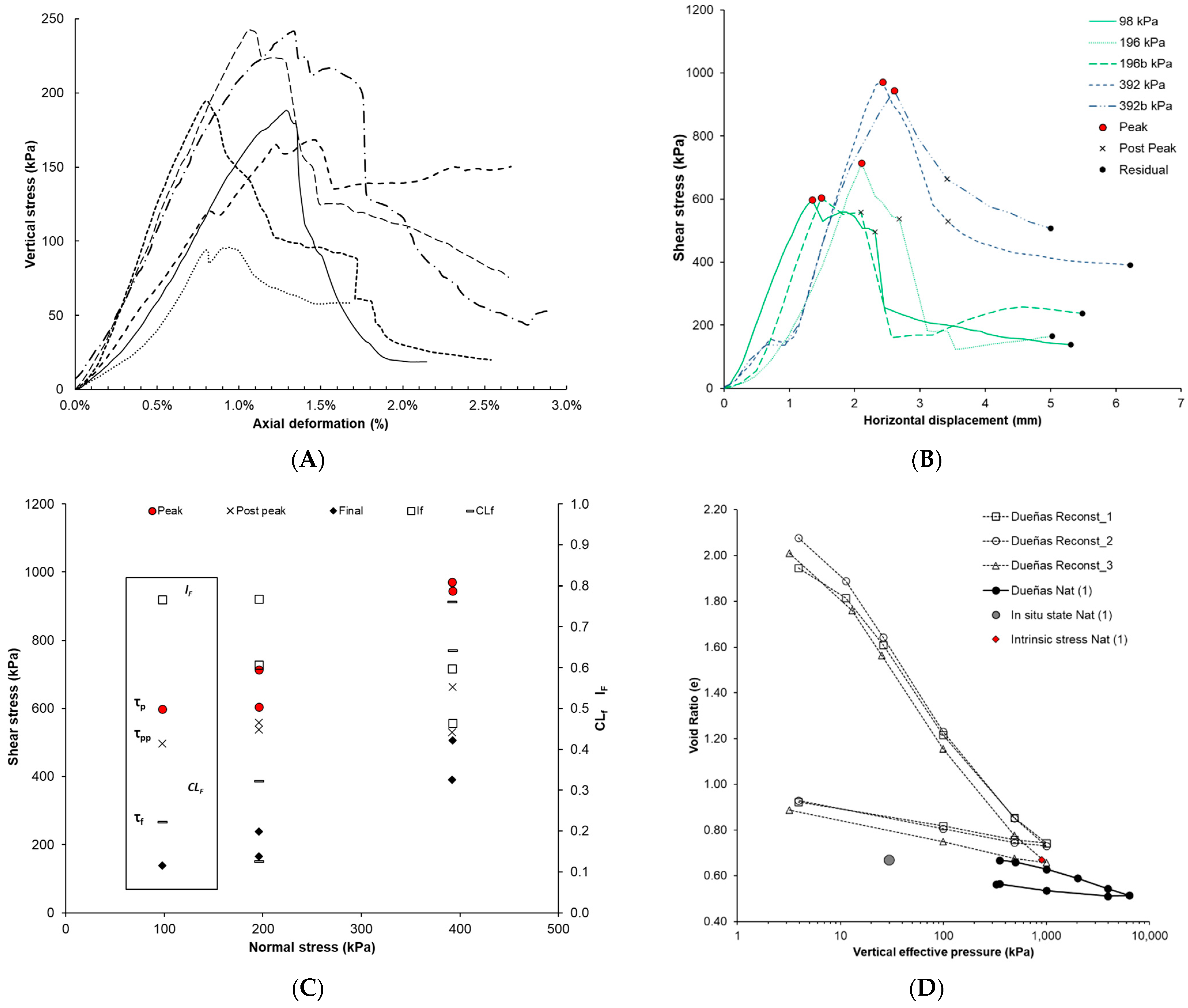
On the unconfined compression tests, the strain–stress curves displayed trajectories with a very well-defined elastic domain, whereas the plastic domain was not clear, defining a peak stress for axial strains not exceeding 1.5% (Figure 6A). An average value of 188 kPa was obtained for the unconfined compressive strength (qu), which corresponds to an undrained shear strength (Su) of 94 kPa (assuming Su equivalent to 0.5·qu).
The samples exhibited a peak strength (τp) for displacements of 1.3–2.6 mm on the direct shear tests (Figure 6B). The average strength values obtained was 766 kPa for τp, and 288 kPa for τf. Before the peak, the behavior was mainly elastic, and after the peak, there were two types of trends: under vertical stress ≤196 kPa, there was a 1 mm displacement that gradually decreased, defining a post-peak strength (τpp) not far from the peak value, and dropping rapidly after this point to reach a continuous strength, considered here as a final strength (τf); on the samples sheared under 392 kPa vertical stress, the strength decreased much more during the first 1 mm post-peak displacement, descending smoothly before reaching the residual stress.

4.4.3. Compressibility

The consolidation curve obtained (Figure 6D) defined a low compression index (Cc 0.15) (Table 5) and a predominant elastic behavior under compression, even at pressures higher than 1000 kPa, with hardly any change being detected in its trajectory. This shape difficulties the approximation towards the preconsolidation pressure (σ′vc) [14]. Nevertheless, the Casagrande construction was applied, obtaining σ′vc of 2000 kPa.
With the reconstituted samples, the consolidation tests defined the intrinsic compression lines (ICLs) for the DC levels. These are plotted in Figure 6D, superimposed onto the natural samples, and cut off by them, which are also common features for OC [12,14,39]. As was expected, the intrinsic properties reflected more compressibility of the soil, on which the geological effects are not impressed (Table 5). The intrinsic and in situ stress are indicated in Figure 6D. The position of the in situ stress, at the left side of the ICL, highlights the overconsolidated state of this clay.

5. Discussion

Throughout the discussion, it is assumed that the geological processes of sediments deposited in marine and continental (lacustrine) basins are different and, therefore, their mechanical behaviors could not be the same.
The alternation of layers of different competence, observed even in the outcrop, imbues the Dueñas Clay formation with an unquestionable heterogeneity, a characteristic that also exists in other formations of the same continental context within the Duero [40,41] and the Tajo Cenozoic basins (Spain) [42,43]. In other types of basins, some differences exist: in the Guadalquivir Basin (Spain), with marine and continental episodes and where the overconsolidated Blue Clay of the Guadalquivir is located, even though rock levels exist (mainly sandstones), they are infrequent [3]. In other marine basins including overconsolidated clay materials, such as the London Clay [44] or the Boston Clay [9], the lithology is more homogeneous and only the variation in the granular fraction gives rise to the identification of singular levels [6,7]. Although each basin has its own unique characteristics, in general, it can be stated that marine basins present more stable conditions compared to continental basins, in addition to marked differences in salinity, greater depth of water, and a higher rate of sedimentation, which is also more continuous [45]. Indeed, the vertical heterogeneity of the studied outcrop is reinforced by the position attributed to the area, at the edge of the center of the basin, where the transition between the alluvial and the lacustrine facies is framed [38]. Therefore, overconsolidated clay formations from continental origin can be considered more heterogeneous than the marine clay formations, and the coexistence of soil and rock behavior materials is a consequence of that.
From the mineralogical composition and microscopic observations, several carbonate cementation episodes have been detected, which are more intense at the upper levels and decrease downwards. On the clay levels at the bottom, inherited palygorskite exists. This mineral provides an idea about the conditions of the sediments—it is considered a mineral indicator of high Si and Mg activity, and a hyper salt medium with high pH (8–10) [37,46], deposited in a more basic environment than those at the marine basins. At the same time, and even in small amounts, smectites caused swelling pressures up to 100 kPa. It must not be ruled out that these pressures may be even higher in more central areas within the basin, where higher contents may exist. Concerning the clay levels, all the processes indicate a post-sedimentation structure for the DC.
  • The role of the carbonate content
As a first approximation, the higher carbonate content in each level, the higher strength, and therefore the results of the Lutton tests, can be explained easily. This is partially correct, as the rock samples are those with a carbonate content above 69 (levels 1, 2, and 3), but the highest carbonate content is not associated with the highest point load strength index. A significant difference in strength was measured between levels 2 and 3, both with a 76% carbonate content. It was observed that the carbonate cement does not always shows the same texture, which in some cases is an eminently micritic cement, and in others is mainly microspharitic, with the rock behavior prevailing. Even for a much lower carbonate content, as in the case of level 5 (42%), the microspharitic cement can govern the rock behavior of the material, in contrast with level 4 (44% of carbonate), in which only micritic carbonate was described. Concerning the clay levels, there is a micritic and scarce cement (12–13% of carbonate) very sensitive to water, which favors its almost instantaneous dissolution, something that does not happen with the sparitic cement in the feldspathic arenites, which are less soluble, thus preventing their collapse. Some authors found similar behavior in saturated biocalcarenites [47], concluding that their strength was related to the origin of the type of bonding: when it is depositional and micrite, its bonding effect disappears when immersed in water, and so the sample collapses partially or completely. However, when bonding of diagenetic origin and the sparite nature of crystals overlap, the strength of the terrain increases and, in addition, the sample is less susceptible to collapse, at least in the short term.
More research is required in the future regarding the role of carbonate in most of the COCs. Nevertheless, the fact that the carbonate reinforcement effect is higher for COCs than for MOCs can be highlighted.
  • Macrostructure
The main macrostructural feature for COCs and MOCs is the existence of discontinuities. Sometimes they cause unexpected behaviours with fatal consequences [48,49]. In addition, it can be stated that, when their presence is very intense, they cause materials with different geological histories to follow the same model of behavior [50]. In the more competent upper levels of the DC Formation, discontinuities are orientated according to the late-alpine orogenic processes [33,34]; in the clayey levels, they display a columnar disposition, which has been previously described as being related to edaphic processes [41]. Moreover, no tectonic effect was observed. Although a more complex tectonic frame sometimes causes preferred orientations in the COC clays, as is the case, for example, in the Dagorda Clay (COC) [51,52], the vertical pattern of the DC presents some differences among the MOCs and COCs, because, in the continental basins, the conditions for vertical fissures are imposed by the alternation of dry and wet periods. Due to its vertical disposition, they should be considered even more carefully, as this orientation reduces the strength of the clay to a minimum [50], and therefore becomes especially relevant for the COC mechanical behavior.
  • Microstructure
On its clay levels, the DC displays a very dense and compact arrangement corresponding to a disperse and stacked structure on which no border-to-face contacts, typical in flocculation structures, were observed. This feature is different to the marine overconsolidated clays (MOCs), where flocculation structures can be seen in the London Clay [6], Oxford Clay [26], and Vallerica Clay [8], and in the Blue Clays of the Guadalquivir [3]. The precipitation of carbonate began after a non-deposition period, creating a coating at very early stages of their geological history, but not very intensely due to the low permeability associated with the fine grain size of the clay levels. At the same time, the absence of a sedimentation period favored the development of organic activity—manifested through bioturbations and s-matrix structures (Figure 4)—and bridges or joints between the clay particles that could be formed during their deposition time. Certain carbonate content is presented in most of the MOCs [8,53], but formed in different moments of the geological history, because it precipitates as the sediments dewater during their burial or appear as occasional crystals [6], and within a different microstructure. A more opened microstructure may be expected for the DC due to the early cementation. However, its non-marine deposition environment prevented the sediment from being in a suspension of low electrolyte concentrations, which would cause the clay minerals to be negatively charged in both its surface and its edge. Such circumstances increase the diffuse double layer and therefore make the electric forces of repulsion predominant. As a result, a dense and elongated structure forms [27], with the layers of clay stacked in domains but without coming into contact with each other and leaving a significant intra-aggregated porosity (Figure 6F), which differs from the most common flocculated structures in MOCs, in which an inter-aggregated porosity is usually much more significant. This structure partially explains the low Cc values measured for the DC when compared with other references of similar materials. Concerning the clays of marine origin (MOCs), the Vallerica Clay reports values between 0.37 and 0.40 [8], and in the Pappadia Clay this index ranges from 0.2 to 0.4 [53]. More similar results have been reported in the Corinth Marl, with Cc = 0.2 [12]. Moreover, considering the COCs, Pietrafitta Clay shows a greater compressibility, with Cc of 0.81 [12], which is smaller than in the Avezatto Clays [13], and quite similar to those from the Viso Clays (Cc = 0.18–0.32) [54]. The common feature of all the clays mentioned is the significant presence of carbonates—of fossiliferous origin—in the MOC and without being part of a cement. With respect to the differences between the DC and the other two COCs, the Pietrafitta Clay and the Avezatto Clay, with the current data, two different circumstances can explain this. First, the type of carbonate, with at least two overimposed processes in the case of the DC; and second, the geological history behind the overconsolidated character of these clays, which is the lithostatic load in the case of the DC and the lowering of the piezometric level for those studied in [13].
  • Preconsolidation pressure
The oedometer compression curves for intact samples show the effect of the geological history, reducing compressibility when compared with the reconstituted samples. The bending in the compression curve is sometimes interpreted due to the maximum lithostatic pressure, which is called the preconsolidation pressure (σ′vc). However, this point can also be affected by other postdepositional processes that usually correspond to pressures higher than those established by geological means. For these cases, [29] introduced the term “vertical yield stress” (σ′vy).
In lacustrine normally consolidated clay, [13] found that yield stress was greater than the in situ stress, and therefore they interpreted this reinforcement caused by the cementation. Assuming that the vertical effective stress is given with sufficient accuracy by the multiple of depth and effective unit weight, γ′ = 10 m kN/m3, the σ′vc of 2000 kPa obtained for the DC would represent an erosion of approximately 200 m above the study area. This value is incompatible with the geological history of the surrounding area, where the location of the Calizas del Páramo Formation at 850 m.a.s.l. is representing an estimation for the infill of the basin [55,56]; compared with the elevation in the sampled area, 730 m.a.s.l., such sediment thickness would have caused a pressure of 1200 kPa, lower than the 2000 kPa obtained in the oedometer. From this perspective, the reinforcement effect of cementation, already described in [13], and in agreement with [57], may explain this mismatch. However, considering the geological interpretation of other authors [58,59], the preconsolidation pressure would agree with the maximum overburden pressure. For these authors, the Calizas del Páramo can be divided into Páramo I and Páramo II, each having a different age and a different position, with the highest located only in the east of the Duero Basin (200 km from the outcrop studied) and the lowest in the center, where the study outcrop is located. According to this interpretation, the gap between these two Paramos would represent additional erosion of 50 to 70 m and, therefore, the preconsolidation pressure agrees with the geological history.
  • Intrinsic versus natural compression curves—the sensitivity framework
The intrinsic consolidation curves are shown in Figure 6D. Concerning the relation between ICL and the natural sample compression line, the location of the in situ stress is at the left side of the intrinsic stress, and the curve cuts the ICL, a common feature for OC [12,14,39]. Nevertheless, the location of its final part it is not usual; it does converge with the ICL and does not even show a break in its slope. Only in [60] is it possible to find a similar trend and, according to them, this occurs when bonding has not been destroyed by the imposed litostatic load. This may also be the explanation for the case of DC.
Considering the sensitivity framework [16], it is possible to compare the mechanical behavior of natural and reconstituted clays, and therefore, to measure the strength caused by the geological history of each clay. Using the definition of the stress sensitivity, Sσ, as the ratio σ′vy/σ*ve, with the results plotted in Figure 6D, a value of 2.2 was obtained for the DC. This is within the range measured in another clay from the Cenozoic Duero Basin, the Viso Clay [57], and similar to the lacustrine Todi and the Pietrafita Clay [12], but lower than the Corinth Marl, which was also studied by the same authors. Considering the geological characteristics of all the mentioned clays, in the case of the DC the role of carbonate is not intense enough to create an interparticle bonding.
  • On the strength of the COC
From the study presented here, values from the unconfined compression tests (UCTs) are up to three times lower than those from the direct shear test (DST). When interpreting strength tests in OC, special care should be taken to ascertain whether the results have been affected by the presence of discontinuities. If so, the strain–stress curves are less sloped and have less marked peak values [3,50,61]. No signs were observed suggesting that discontinuities were affecting the tests, either in the laboratory when removing the samples tested, or in the morphology of the breaking curves. Thus, the obtained parameter Su represents situations in which isotropic failure occurs through the matrix. Considering the importance of the anisotropic behavior in the OC [15,48,49], larger samples should be used for further studies, because it is expected that in a higher volume, failure may be affected by these singular planes. After discarding the discontinuity effects on the UCT as an explanation for the low values in the UCT, the conclusion reached is that the DST reports more realistic values for Su than the UCT, as the latter clearly underestimates the strength of the clay.
From a professional practice perspective, the Technical Construction Code [62] contemplates the possibility for OC to estimate settlement based on an elastic behavior, provided that the pressure transmitted is lower than its unconfined compression strength (qu). In this regard, the obtained consolidation curves for the clayey levels are the result of a mainly elastic behavior and seem to be the mechanism at least up to about 2000 kPa. Therefore, plastic settlement would be significant only for pressures above this value, outside the margins in which the construction takes place, and fulfilling the asseveration included in the Code.
Regarding the mechanics of the strength, stiff behavior was observed in the clay levels of the DC, similarly to that reported in MOC of the Guadalquivir Blue Clay [3] or the London Clay [15]. Nevertheless, some differences are apparent considering the strain–stress curves, the brittleness index defined as If = (τp − τf)/(τp), and the cementation loss (CLf) = (τp − τpp)/ (τp − τpf) [50]. For the former, the values are in the range 0.5–0.8, with an average of 0.6, and represent a measure of the total loss of strength. Moreover, the values of CLf are indicative of a similar loss “before post peak” and “after post peak” for samples sheared at high vertical stresses, CLf = 0.6–0.8; whereas at lower stress, CLf = 0.2–0.3, indicating that a large proportion of the peak strength is lost after a significant post-peak displacement (Figure 6C). As previously mentioned, the low proportions of smectite induce swelling in the clay levels, and this in turn decreases their expected brittle behavior. Similar effects have been described previously in other clays [63]. In high vertical stress tests, at a swelling pressure three times higher than that measured, the volume increase is aborted by the vertical load and, therefore, the action of the swelling is prevented.

6. Conclusions

The DC Formation is a heterogeneous continental origin deposit, on which clays, feldspathic arenites, sandy lutites, and silicate sand levels coexist. This circumstance contributes to an additional singularity when compared with other formations of marine origin, which are usually much more homogeneous, and causes rock and soil material behavior to coexist.
Post-depositional processes such as carbonate cementation, edaphic activity and overconsolidation have been described, with the former existing in all the facies, controlling the alterability of the different levels and their mechanical properties, in such a way that the sparite cement reduces the alterability of the samples against the water.
The main macrostructures detected in the DC Formation are the stratification surfaces and, in the case of the lutitic levels, some discontinuities related to the regional deformation orientations. On the clayey levels, only some columnar discontinuities are observed, caused probably by edaphic processes.
The microstructure of the clayey levels in the DC Formation is dense and compact, and fundamentally a laminar type, and processes of flocculation were not detected. This circumstance is related to the lacustrine context in which the sediments were deposited. In addition, the carbonate content, acting as a cement and not as a fossil material, as happens in some marine clays, can explain why these continental origin clays display a much lower compressibility than those from marine origin.
The mechanical behavior of the clay levels is mainly brittle, but the presence of smectite and its swelling potential decrease this behavior when shearing takes place under normal stresses equal to or below its swelling pressure. Under uniaxial consolidation, the preconsolidation pressure indicates an erosion of 200 m in this area, which supports the geological interpretation of a clogging surface at 920 m.a.s.l for the continental Duero Basin, seventy meters above the position assumed by the surrounding elevations.
When studying the undrained shear strength of the silicate clay levels, direct shear tests report more realistic values than the UCT, a test that, in this case, clearly underestimates the strength of the clay. From the deformational point of view, the usual settlement that a civil or edification work may trigger in the clay levels of this formation will be elastic, because the yield pressure, which for these clays matches the preconsolidation pressure, is significantly higher than those usually transmitted by the normally adopted foundations.
Throughout this study, evidence was found that geological processes in marine and continental (lacustrine) environments give rise to sediments with different macro and microstructural features, which also affect their mechanical responses. This provides opportunities for further research on this topic.

Author Contributions

Conceptualization and methodology, J.N.; Structure observations: J.N., J.A.B., M.S. and E.G.-R.; Writing—original draft preparation, J.N.; Writing—review: J.N., M.Y., J.A.B., S.M. and E.G.-R. All authors have read and agreed to the published version of the manuscript.

Funding

This research received no external funding.

Institutional Review Board Statement

Not applicable.

Conflicts of Interest

The authors declare no conflict of interest.

References

  1. Bilotta, E.; Stallebrass, S.E. Prediction of Stresses and Strains around Model Tunnels with Adjacent Embedded Walls in Overconsolidated Clay. Comput. Geotech. 2009, 36, 1049–1057. [Google Scholar] [CrossRef] [Green Version]
  2. Fernández, J.M.G.; Checa, M.; Pérez, C.; Williams, B.; Pozo, V. Caracterización de Detalle de de Las Margas Azules Del Guadalquivir Mediante Ensayos in Situ y de Laboratorio. Ingeopres Actual. Técnica Ing. Civ. Min. Geol. Medio Ambiente 2009, 186, 16–22. [Google Scholar]
  3. Tsige, M. Microfábrica y Mineralogía de Las Arcillas Azules Del Guadalquivir: Influencia En Su Comportamiento Geotécnico; Centro de Estudios y Experimentación de Obras: Madrid, Spain, 1999; ISBN 9788449804267. [Google Scholar]
  4. Pusch, R. Experience from Preparation and Investigation of Clay Microstructure. Eng. Geol. 1999, 54, 187–194. [Google Scholar] [CrossRef]
  5. Stallebrass, S.E.; Atkinson, J.H.; Mašín, D. Manufacture of Samples of Overconsolidated Clay by Laboratory Sedimentation. Géotechnique 2007, 57, 249–253. [Google Scholar] [CrossRef]
  6. Gasparre, A. Advanced Laboratory Characterisation of London Clay. Ph.D. Thesis, Imperial College London, London, UK, 2005. [Google Scholar]
  7. Gasparre, A.; Nishimura, S.; Coop, M.R.; Jardine, R.J. The influence of structure on the behaviour of London Clay. Géotechnique 2007, 57, 19–31. [Google Scholar] [CrossRef]
  8. Amorosi, A.; Rampello, S. An experimental investigation into the mechanical behaviour of a structured stiff clay. Géotechnique 2007, 57, 153–166. [Google Scholar] [CrossRef]
  9. Santagata, M.; Kang, Y.I. Effects of Geologic Time on the Initial Stiffness of Clays. Eng. Geol. 2007, 89, 98–111. [Google Scholar] [CrossRef]
  10. Wilkinson, S.; Fenton, C. The Application of Stereo E-SEM in Understanding 3D Mudrock Structure. In Proceedings of the 11th IAEG Congress, Auckland, New Zealand, 10–14 September 2010; pp. 5–10. [Google Scholar]
  11. Sorensen, K.K.; Baudet, B.A.; Simpson, B. Influence of Structure on the Time-Dependent Behaviour of a Stiff Sedimentary Clay. Géotechnique 2007, 57, 113–124. [Google Scholar] [CrossRef] [Green Version]
  12. Burland, J.B.; Rampello, S.; Georgiannou, V.N.; Calabresi, G. A Laboratory Study of the Strength of Four Stiff Clays. Géotechnique 1996, 46, 491–514. [Google Scholar] [CrossRef]
  13. Burghignoli, A.; Miliziano, S.; Soccodato, F.M. Cementation Effects in Two Lacustrine Clayey Soils. Geotech. Geol. Eng. 2010, 28, 815–833. [Google Scholar] [CrossRef]
  14. Burland, J.B. On the Compressibility and Shear Strength of Natural Clays. Géotechnique 1990, 40, 329–378. [Google Scholar] [CrossRef]
  15. Chandler, R.J. The Third Glossop Lecture Clay Sediments in Depositional Basins: The Geotechnical Cycle. Q. J. Eng. Geol. Hydrogeol. 2000, 33, 7–39. [Google Scholar] [CrossRef]
  16. Chandler, R.J.; Cotecchia, F. A General Framework for the Mechanical Behaviour of Clays. Géotechnique 2000, 50, 431–447. [Google Scholar]
  17. Escolano, F.; Bueno, M. Analysis of a Dilatometer Test in Over-Consolidated Sediments, Basin of the Duero River, Spain. Acta Geotech. Slov. 2015, 12, 37–47. [Google Scholar]
  18. Armenteros, I.; Corrochano, A.; Alonso-Gavilán, G.; Carballeira, J.; Rodríguez, J.; Armenteros, I.; Corrochano, A.; Alonso, G.G.; Carballeira, J.; Rodríguez, J.M. Geology of Spain; Gibbons, W., Moreno, M., Eds.; Geological Society of London: London, UK, 2002; pp. 309–315. ISBN 9781862391277. [Google Scholar]
  19. Torrero, C.; Nespereira, J.; Yenes, M.; Monterrubio, S. Modelling the Behaviour of Stiff Clays from Continental Origin in Tunnel Construction: Back Analysis of the First Stage of the El Almendro Tunnel. In Proceedings of the 17th European Conference on Soil Mechanics and Geotechnical Engineering, ECSMGE 2019–Proceedings, Reykjavík, Iceland, 1–6 September 2019. [Google Scholar]
  20. IAEG. Rock and Soil Description and Classification for Engineering Geological Mapping. Bull. Int. Assoc. Eng. Geol. 1981, 24, 235–274. [Google Scholar] [CrossRef]
  21. Belokas, G.; Kavvadas, M. An Intrinsic Compressibility Framework for Clayey Soils Position of ICC p Mean or Isotropic Effective Stress. Geotech. Geol. Eng. 2011, 29, 855–871. [Google Scholar] [CrossRef]
  22. Alonso-Gavilán, G.; Armenteros, I.; Carballeira, J.; Corrochano, A.; Huerta, P.; Rodríguez, J. Cuenca del Duero. In Geología de España; Vera, J., Ed.; Sociedad Geológica de España-Instituto Geológico y Minero de España: Madrid, Spain, 2004; pp. 550–555. [Google Scholar]
  23. Hallsworth, C.; Knox, R. BGS Rock Classification Scheme. Volume 3, Classification of Sediments and Sedimentary Rocks; British Geological Survey: Nottingham, UK, 1999. [Google Scholar]
  24. Bullock, P.; Fedroroff, N.; Jongerius, A. Handbook for Soil Thin Section Description; Waine Research Publications: Albrighton, UK, 1985; ISBN 9780905184098. [Google Scholar]
  25. Mitchell, J. Fundamentals of Soil Behaviour; John Wiley & Sons: Hoboken, NJ, USA, 1976; ISBN 9780471463023. [Google Scholar]
  26. Wilkinson, S.; Fenton, C. The Influence of Geological History on Preferred Particle Orientation and the Observed Anisotropy of Over Consolidated UK Mudrocks. In Proceedings of the Engineering Geology for Society and Territory, Torino, Italy, 15–19 September 2014; Lollino, G., Giordan, D., Thuro, K., Carranza-Torres, C., Wu, F., Marinos, P., Delgado, C., Eds.; Springer International Publishing: Cham, Switzerland, 2015; Volume 6, pp. 805–808. [Google Scholar]
  27. González de Vallejo, L.; Ferrer, M.; Ortuño, L.; Oteo, C. Ingeniería Geológica; Pearson Education: London, UK, 2002; ISBN 8420531049. [Google Scholar]
  28. AENOR. Standard Test Methods for Geotechnical Tests (Soils); Spanish Association of Standardization and Certification: Madrid, Spain, 1999. [Google Scholar]
  29. Wood, L.E.; Deo, P. A Suggested System for Classifying Shale Materials for Embankments. Bull. Assoc. Eng. Geol. 1975, 12, 39–55. [Google Scholar]
  30. Lutton, R.J. Slaking Indexes for Design; United States Federal Highway Administration Offices of Research & Development: McLean, VA, USA, 1977. [Google Scholar]
  31. Miščević, P.; Vlastelica, G. Durability Characterization of Marls from the Region of Dalmatia, Croatia. Geotech. Geol. Eng. 2011, 29, 771–781. [Google Scholar] [CrossRef]
  32. Vlastelica, G.; Miscevic, P.; Pavic, N. Testing the Shear Strength of Soft Rock at Different Stages of Laboratory Simulated Weathering. J. Croat. Assoc. Civ. Eng. 2017, 68, 955–965. [Google Scholar] [CrossRef] [Green Version]
  33. Pérez, A.; Elizaga, E. Mapa Geológico de España 1:50,000, hoja n°372 (Valladolid); IGME: Madrid, Spain, 1979. [Google Scholar]
  34. Yenes, M.; Monterrubio, S.; Nespereira, J.; Santos, G.; Fernández-Macarro, B. Large Landslides Induced by Fluvial Incision in the Cenozoic Duero Basin (Spain). Geomorphology 2015, 246, 263–276. [Google Scholar] [CrossRef]
  35. Flügel, E. Microfacies of Carbonate Rocks; Springer: Berlin/Heidelberg, Germany, 2004; ISBN 978-3-662-08728-2. [Google Scholar]
  36. Blanco, J. Procesos de Alteración Meteórica En Series Continentales Arcósicas: Ejemplo Del Paleógeno Del Borde SW de La Cuenca Del Duero. In Proceedings of the Dinámica de las Interacciones Ente Agua y Minerales en Medios de Baja Temperatura (Meteorización, Diagénesis, Metasomatismo), Salamanca, Spain, 28 September 1999. [Google Scholar]
  37. Garcia-Romero, E.; Suarez, M. Sepiolite-Palygorskite Polysomatic Series: Oriented Aggregation as a Crystal Growth Mechanism in Natural Environments. Am. Mineral. 2014, 99, 1653–1661. [Google Scholar] [CrossRef] [Green Version]
  38. Delgado, J.; Del Valle, A. La Geología de La Provincia de Valladolid; Diputación de Valladolid: Valladolid, Spain, 2007. [Google Scholar]
  39. Takahashi, A.; Fung, D.W.H.; Jardine, R.J. Swelling Effects on Mechanical Behaviour of Natural London Clay. In Proceedings of the 16th International Conference on Soil Mechanics and Geotechnical Engineering, Osaka, Japan, 12–16 September 2005; Volume 16, pp. 443–446. [Google Scholar]
  40. Armenteros, I.; Corrochano, A. Los Sistemas Lacustres de La Cuenca Terciaria Del Duero. Acata Geol. Hisp. 1989, 24, 259–279. [Google Scholar]
  41. Armenteros, I. Contribucion al Conocimiento Del Mioceno Lacustre de La Cuenca Terciaria Del Duero Sector Centro-Oriental, Valladolid-Penafiel. Acata Geol. Hisp. 1991, 26, 97–131. [Google Scholar]
  42. Doval, M.; García Santiago, P.; Domínguez, M.C.; Brell, J. Mineralogía de Las Arcillas de Las Facies Evaporíticas de La Cuenca Del Tajo. Trab. Geol. 1985, 15, 1–8. [Google Scholar]
  43. De Santiago Buey, C.; Barrios, M.S.; Romero, E.G.; Montoya, M.D. Mg-Rich Smectite “Precursor” Phase in the Tagus Basin, Spain. Clays Clay Miner. 2000, 48, 366–373. [Google Scholar] [CrossRef]
  44. De Freitas, M.H.; Mannion, A. Biostratigraphy for the London Clay in London. Géotechnique 2007, 57, 91–99. [Google Scholar] [CrossRef]
  45. Vera Torres, J. Estratigrafía: Principios y Métodos; Rueda: Alcorcón, Spain, 1994; ISBN 9788472070745. [Google Scholar]
  46. Jones, B.F.; Galan, E. Chapter 16: Sepiolite and Palygorskite. In Hydrous Phyllosilicates; Bailey, S.W., Ed.; Reviews in Mineralogy; Mineralogical Society of America: Washington, DC, USA, 1988; Volume 19, pp. 631–674. ISBN 0-939950-23-5. [Google Scholar]
  47. Ciantia, M.O.; Castellanza, R.; Crosta, G.B.; Hueckel, T. Effects of Mineral Suspension and Dissolution on Strength and Compressibility of Soft Carbonate Rocks. Eng. Geol. 2015, 184, 1–18. [Google Scholar] [CrossRef]
  48. Alonso, E.; Gens, A. Aznalcóllar Dam Failure. Part 1: Field Observations and Material Properties. Géotechnique 2006, 56, 165–183. [Google Scholar] [CrossRef] [Green Version]
  49. Ayala-Carcedo, F.J. La Rotura de La Balsa de Residuos Mineros de Aznalcóllar (España) de 1998 y El Desastre Ecológico Consecuente Del Río Guadiamar: Causas, Efectos y Lecciones. Boletín Geol. Min. 2004, 115, 711–738. [Google Scholar]
  50. Vitone, C.; Viggiani, G.; Cotecchia, F.; Hall, S.A. Localized Deformation in Intensely Fissured Clays Studied by 2D Digital Image Correlation. Acta Geotech. 2013, 8, 247–263. [Google Scholar] [CrossRef]
  51. Nunes Veiga, A. Caracterizacao Geotécnica Dos Terrenos Do Vale Tifónico Parceiros-Leiria. Ph.D. Thesis, Universidade de Coimbra, Coimbra, Spain, 2011. [Google Scholar]
  52. Veiga, A.; Quinta-Ferreira, M. Characterization of the Dagorda Claystone in Leiria, Portugal, Based on Laboratory Tests. In Engineering Geology for Society and Territory–Volume 6; Springer International Publishing: Cham, Switzerland, 2015; pp. 685–688. [Google Scholar]
  53. Cotecchia, F.; Cafaro, F.; Aresta, B. Structure and Mechanical Response of Sub-Apennine Blue Clays in Relation to Their Geological and Recent Loading History. Géotechnique 2007, 57, 167–180. [Google Scholar] [CrossRef]
  54. Nespereira, J.; Suárez, M.; Monterrubio, S.; Yenes, M.; Herrera, D. Compresibilidad de Arcillas Sobreconsolidadas de Origen Continental: Estado Reconstituido, Sedimentado y Natural. In Proceedings of the Geo-Temas, Huelva, Spain, 10–14 September 2016; Morales, J.A., Carro, B.M., Miguel, A., Camacho, M.A., Eds.; Geo-Temas: Huelva, Spain, 2016; Volume 1, pp. 957–960. [Google Scholar]
  55. Portero, J.; Del Olmo, P.; Ramírez del Pozo, J.; Varjas, I. Síntesis Del Terciario Continental de La Cuenca Del Duero. In Proceedings of the I Reunión Nacional de la cuenca del Duero, Salamanca, Spain, 8–10 September 1982; pp. 11–37. [Google Scholar]
  56. Portero, J.; Olivé, A. El terciario del borde meridional del Guadarrama y Somosierrae. In Geología de España. Libro jubilar JM Ríos; Comba, J., Ed.; Instituto Geológico y Minero de España: Madrid, Spain, 1984; pp. 527–543. [Google Scholar]
  57. Jiménez-Salas, J.A.; de Justo-Alapañés, J.L. Geotecnia y Cimientos I: Propiedades de Suelos y de Rocas; Rueda: Madrid, Spain, 1975; ISBN 8472070085. [Google Scholar]
  58. Luengo, J.; Nozal, F.; Peláez-Campomanes, P.; Montes, M.; Armenteros, I.; López, F.; García, I. Leading Factors of Fluvial/Lacustrine Castillejo de Robledo Intrabasinal Infill (Southeastern Border of the Duero Basin, Spain). In Proceedings of the 27th IAS Meeting of Sedimentology, Alghero, Italy, 20–23 September 2009; p. 582. [Google Scholar]
  59. Nozal, F.; Herrero, A. El Mioceno Del Borde Meridional Del Corredor Aranda de Duero- Burgo de Osma (SE Cuenca Del Duero). Rev. Soc. Geol. Esp. 2005, 18, 21–37. [Google Scholar]
  60. Anagnostopoulos, A.G.; Kalteziotis, N. Geotechnical Properties of the Corinth Canal Marls. Geotech. Geol. Eng. 1991, 9, 1–26. [Google Scholar] [CrossRef]
  61. Gasparre, A.; Nishimura, S.; Minh, N.A.; Coop, M.R.; Jardine, R.J. The Stiffness of Natural London Clay. Géotechnique 2007, 57, 33–47. [Google Scholar] [CrossRef]
  62. Ministerio de la Vivienda, Real Decreto 314/2006. Código Técnico de la Edificación. 2006, 1–1061. Available online: https://www.codigotecnico.org/pdf/Documentos/SE/DBSE-C.pdf (accessed on 16 December 2021).
  63. Morgensten, N. Geotechnical Aspects of Environmental Control. In Proceedings of the 11th International Conference on Soil Mechanics and Foundation Engineering, San Francisco, CA, USA, 12–16 August 1985; Volume 1, pp. 155–185. [Google Scholar]
Figure 1. Geological map of the central area of the Duero Basin (modified from Yenes et al. 2015).
Applsci 11 12021 g001
Figure 2. The DC Formation in the outcrop studied: (A) general view of the outcrop; (B) calcarenitic levels are predominant at the top; (C) intermediate levels; (D) bottom of the facies.
Applsci 11 12021 g002
Figure 3. Discontinuities identified in the outcrop.
Applsci 11 12021 g003
Figure 4. Microstructured features observed under petrographic microscopy. (A) Fine-grained laminated feldspathic arenite. In the upper central part of the image, there is a crusted area approximately 1 mm long (pelloid). (B) Carbonate nodulus in a feldesphatic arenite. (C) Sandy lutite with quartz grains in a reorganized clay matrix with an S-matrix microstructure (parallel polarized light, PPL). (D) Sandy lutite with quartz grains in a reorganized clay matrix with an S-matrix microstructure (crossed polarized light, CPL). (E) Sandy silicate clays with an incipient carbonate crust. The darker area corresponds to a more developed crust (NPL). (F) Sandy silicate clays with an incipient carbonate crust. The darker area corresponds to a more developed crust (CPL). (G) Burrow filled and surrounded by a carbonate crust (NPL). (H) Silicate sand with grain-striated or b-striated fabric, and around the clasts—quartz and feldspars, fundamentally—the arrangement of the clays as a border, evidence of paleo-edaphic processes (CPL).
Applsci 11 12021 g004aApplsci 11 12021 g004b
Figure 5. Scanning electron micrographs of the clay levels. (A) General view of the massive and laminar texture of the clayey levels, with coarse quartz grains (Q), some dolomitic rhombic crystals (Do), and palygorskite fibers. (B) Stacked clays with domains defined by overlapping face-to-face contacts. (C) Triple point structures originated by the orientation of clay minerals normal to the bedding plane. (D) Detail of the triple point structure.
Applsci 11 12021 g005
Figure 6. Results of uniaxial compression, direct shear, and oedometer tests. (A) Uniaxial compression tests. (B) Direct shear tests. (C) Normal stress and peak shear stress obtained from the shear tests. (D) Oedometer tests with natural and reconstituted samples.
Applsci 11 12021 g006
Table 1. Mineralogy of the clay levels identified within the DC Formation. The mineralogical semi-quantification was also performed using the oriented aggregates (OA) and after applying the method of reflective powers.
LevelQuartzCalciteDolomiteK-FeldsparSmectiteIllitePalygorskite
616192142929
81193383333
Table 2. Orientation and main features of the discontinuities in the DC Formation.
FamilyStrike/DipSpacing (cm)Persistence (m)MorphologyAperture (mm)
BeddingHorizontal20–601–3Undulated, rough3
1N 272/9020–601–3Undulated, smooth-
2N 243/9020–601–3Undulated, smooth-
3N 353/9020–601–3Undulated, smooth-
Table 3. Dry density, porosity (n), carbonate content (%), and collapsed mass (%) in the submerged water test. On the rock levels, results of the absorption test and (Is50) point load strength index. The petrographic name for each level is indicated.
LevelPetrographic NameDry Density (Mg/m3)n (%)Carbonate Content (%)Collapsed Mass (%)Absorption (%)Is50 (MPa)
1Feldspathic arenite2.3113%69180.8
2Feldspathic arenite2.1419%769110.9
3Sandy carbonated lutite2.0024%76112.50.4
4Feldspathic arenite1.7634%44100--
5Feldspathic arenite2.2615%421.552.0
6Sandy clay1.6636%13100--
7Silicate sand1.9028%5100--
8Sandy clay1.6536%12100--
Table 4. Summary of the data from tests carried out with the cohesive levels. (W), moisture content; (WL), liquid limit; (WP), plastic limit; (e), void ratio; (Sr), degree of saturation; (qu), unconfined compression strength; (γ) unit weight; (Su), undrained shear strength; (DST), direct shear test.
ParameterMaximumAverageMinimumStd. DeviationNumber of Data
Fine particles (%)928170526
W (%)30193626
WL755946126
IP38292266
γap20.819.718.70.6916
e1.120.780.510.274
Sr10.870.700.124
qu (kPa)1019079163
DST-Su (kPa)971766.35981815
DST-Su,res (kPa)5062881391565
Table 5. Compression characteristics as determined by the oedometer tests using natural and reconstituted samples. (eo), initial void ratio; (Cc), compression index; (Cs), swelling index; (*), intrinsic properties.
SampleBulk Density (Mg/m3)eoCcCc *Cs
DUEÑAS_RECONST_11.5851.983-0.473-
DUEÑAS_RECONST_21.5862.133-0.502-
DUEÑAS_RECONST_31.6472.234-0.500-
Dueñas_Nat_11.9430.670.149-0.03
Publisher’s Note: MDPI stays neutral with regard to jurisdictional claims in published maps and institutional affiliations.